Advertisement
Quick Links
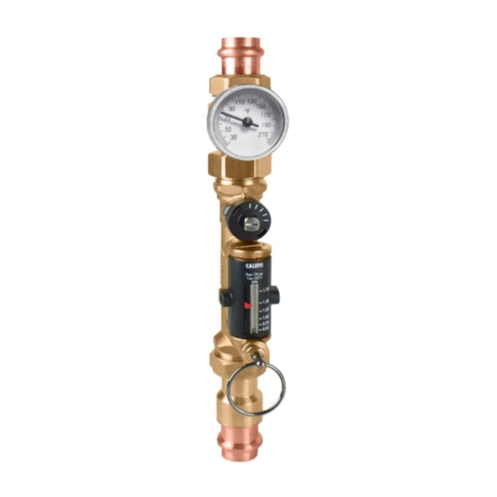
QuickSetter + ™ Low-lead
balancing valve with flow meter
132 series
Product range
132 series
Balancing valve with flow meter, includes check valve
and optional outlet temperature gauge.............................................................connections
Technical specifications
Materials
Valve
Body:
Ball:
Ball control stem:
Ball seal seat:
Control stem guide:
Seals:
Flow meter
Body and headwork:
Bypass valve stem:
Springs:
Seals:
Flow meter float and indicator cover:
NSF/ANSI 372-2011, Drinking Water System Components-Lead Content
Reduction of Lead in Drinking Water Act, California Health and Safety Code
116875 S.3874, Reduction in Drinking Water Act, certified by ICC-ES, file PMG-1360.
Performance
Suitable Fluids:
Max. percentage of glycol:
Max. working pressure:
Working temperature range:
Flow rate range unit of measurement:
Accuracy:
Control stem angle of rotation:
Control stem adjustment wrench:
Connections
Main connections:
Lay length (press connection):
DZR low-lead brass
stainless steel
brass, chrome plated
PTFE
PSU
EPDM
DZR low-lead brass
stainless steel
stainless steel
EPDM
PSU
water, glycol solutions
50%
150 psi (10 bar)
14 - 230°F (-10–110°C)
1/2 - 1 ¾ gpm
2 - 7 gpm
±10%
90°
9 mm
½", ¾", 1"
sweat union
¾"
press union
size
¾
inch without gauge: 7
5 /16
"
size
¾
inch with gauge: 10
1 /8
"
ACCREDITED
ISO 9001 No. 0003
ISO 9001 FM 21654
Function
The QuickSetter+™ manual balancing valve contains a built-in flow
meter and sight gauge, negating the need for differential pressure
gauges and reference charts. Circuit balancing is fast, easy and
accurate. Constructed of DZR low-lead brass, QuickSetter+™ is
ideally suited for use in plumbing applications such as hot water
recirculation systems. The built-in check valve protects against circuit
thermo-siphoning. The outlet temperature gauge (optional) verifies the
fluid temperature in the circuit. The flow meter sight gauge is dry (not
exposed to the fluid) thus eliminating the possibility of gauge clouding/
scaling over time. The QuickSetter+™ can also be used in heating
systems.
½", ¾", 1"
Flow rate ranges
Code
Connection
½" sweat
132439AFC
¾" press
132536AFC
¾" sweat
132539AFC
1" sweat
132639AFC
½" sweat
132459AFC
¾" press
132556AFC
¾" sweat
132559AFC
1" sweat
132659AFC
Code
Connection
132438AFC*
½" sweat
132537AFC*
¾" press
¾" sweat
132538AFC*
1" sweat
132638AFC*
½" sweat
132458AFC*
¾" press
132557AFC*
¾" sweat
132558AFC*
1" sweat
132658AFC*
*with temperature gauge.
CALEFFI
01283/16 NA
Replaces 01283/14 NA
sweat union and
¾"
press union
Fully
open
Flow rate (gpm)
Cv
0.5 - 1.75
1.0
0.5 - 1.75
1.0
0.5 - 1.75
1.0
0.5 - 1.75
1.0
2.0 - 7.0
6.3
2.0 - 7.0
6.3
2.0 - 7.0
6.3
2.0 - 7.0
6.3
Fully
open
Flow rate (gpm)
Cv
0.5 - 1.75
1.0
0.5 - 1.75
1.0
0.5 - 1.75
1.0
0.5 - 1.75
1.0
2.0 - 7.0
6.3
2.0 - 7.0
6.3
2.0 - 7.0
6.3
2.0 - 7.0
6.3
Advertisement

Subscribe to Our Youtube Channel
Related Manuals for CALEFFI QuickSetter+ 132 Series


Summary of Contents for CALEFFI QuickSetter+ 132 Series
- Page 1 QuickSetter + ™ Low-lead CALEFFI balancing valve with flow meter 132 series 01283/16 NA ACCREDITED Replaces 01283/14 NA ISO 9001 No. 0003 ISO 9001 FM 21654 Function The QuickSetter+™ manual balancing valve contains a built-in flow meter and sight gauge, negating the need for differential pressure gauges and reference charts.
- Page 2 Dimensions 110 130 ˚F 110 130 ˚F 150 psi 230˚F 150 psi 1.75 1.75 230˚F 1.50 1.50 1.75 1.75 1.50 1.50 1.25 1.25 1.00 1.00 1.25 1.25 0.75 0.75 0.50 0.50 1.00 1.00 0.75 0.75 0.50 0.50 Code (lb) 132439AFC 1/2"...
-
Page 3: Operating Principle
Operating principle Hydraulic characteristics at 100% open The balancing valve is a hydraulic device that ∆p (psi) (psi) (bar) (feet of head) 1/2 - 1-3/4 gpm 2 - 7 gpm 46.00 controls flow rate. The control mechanism is a ball valve (1), operated by a control stem (2). 20.00 The flow rate is manually and properly set by use of the convenient onboard flow meter (3) -
Page 4: Installation
The valve can be installed in any position with respect to the flow direction shown on the valve body. Additionally, the valve can be installed either horizontally or vertically. CALEFFI CALEFFI D. Once the flow rate is properly adjusted, release the operating... -
Page 5: Specification Summary
We reserve the right to change our products and their relevant technical data, contained in this publication, at any time and without prior notice. Caleffi North America, Inc. 3883 W. Milwaukee Road Milwaukee, WI 53208 Tel: 414-238-2360 · Fax: 414-238-2366 sales@caleffi.com · www.caleffi.com © Copyright 2016 Caleffi North America, Inc.
Need help?
Do you have a question about the QuickSetter+ 132 Series and is the answer not in the manual?
Questions and answers