Table of Contents
Advertisement
38MA*R
Outdoor Unit Single Zone Ductless System
Sizes 09 to 36
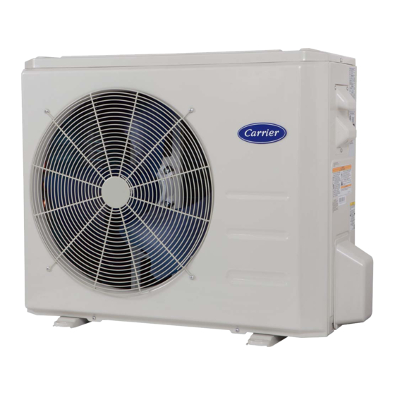
Fig. 1 -Sizes 9K to 36K
NOTES: Read the entire instruction manual before starting the
installation.
Images are for illustration purposes only. Actual
models may differ slightly.
Installation Instructions
Specifications subject to change without notice.
TABLE OF CONTENTS
SAFETY CONSIDERATIONS........................................................2
INTRODUCTION ............................................................................3
ACCESSORIES................................................................................3
DIMENSIONS..................................................................................4
CLEARANCES ................................................................................7
INSTALLATION REQUIREMENTS .............................................8
INSTALLATION .............................................................................8
Step 1 - Check Equipment ................................................................8
Step 2 - Mount Unit ..........................................................................8
Step 3 - Condensate Drain Installation .............................................9
Step 4 - Refrigerant Piping ...............................................................10
Step 5 - Evacuate Coil And Tubing System .....................................13
Step 6 - Electrical Connections.........................................................14
WIRING ...........................................................................................14
ELECTRICAL DATA......................................................................15
CONNECTION DIAGRAMS ..........................................................15
START-UP .......................................................................................16
CARE AND MAINTENANCE........................................................16
TROUBLESHOOTING ...................................................................16
OUTDOOR UNIT DIAGNOSTIC GUIDES ...................................17
DUCTLESS START-UP CHECKLIST ...........................................18
PAGE
Advertisement
Table of Contents

Subscribe to Our Youtube Channel
Related Manuals for Carrier 38MA R Series


Summary of Contents for Carrier 38MA R Series
-
Page 1: Table Of Contents
38MA*R Outdoor Unit Single Zone Ductless System Sizes 09 to 36 Installation Instructions TABLE OF CONTENTS PAGE SAFETY CONSIDERATIONS............2 INTRODUCTION ................3 ACCESSORIES................3 DIMENSIONS..................4 CLEARANCES ................7 INSTALLATION REQUIREMENTS ..........8 INSTALLATION ................8 Step 1 - Check Equipment ..............8 Step 2 - Mount Unit ................8 Step 3 - Condensate Drain Installation ..........9 Step 4 - Refrigerant Piping ...............10 Step 5 - Evacuate Coil And Tubing System ........13... -
Page 2: Safety Considerations
SAFETY CONSIDERATIONS WARNING Installing, starting up, and servicing air- conditioning equipment can be hazardous due to system pressures, electrical components, and equipment location (roofs, elevated structures, etc.). ELECTRICAL SHOCK HAZARD Failure to follow this warning could result in personal injury or Only trained, qualified installers and service mechanics should install, start- up, and service this equipment. -
Page 3: Introduction
INTRODUCTION NOTE: - If the outdoor unit is higher than the indoor unit, prevent rain The Horizontal Discharge Outdoor units are R-410A condensing units from flowing into the indoor unit along the connection pipe by designed with application flexibility in mind. These units have a max making a downward arc in the connection pipe before it enters total piping length up to 164 ft (50 m) and a maximum piping lift of the wall to the indoor unit. -
Page 4: Dimensions
DIMENSIONS Air inlet Air outlet Fig. 3 — Outdoor Unit Table 3 — Outdoor Unit UNIT SIZE VOLTAGE 115V 208/230V 208/230V 208/230V 208/230V 208/230V 208/230V HEIGHT (H) IN (MM) 21.81 (554) 21.81 (554) 21.81 (554) 27.63 (702) 31.89 (810) 31.89 (810) 31.89 (810) WIDTH (W) IN (MM) - Page 5 DIMENSIONS (CONT) 33.69 in (856mm) 27.68 in (703mm) 14.84 in (377mm) 2.80 in (71mm) 21.28 in (540mm) 0.51 in (13mm) 33.19 in (843mm) 2.61 in (66mm) 0.47 in (12mm) 13.80 in (351mm) 13.69 in (348mm) 2.39 in (61mm) 3.64 in (92mm) 14.84 in (377mm) Fig.
- Page 6 DIMENSIONS (CONT) 37.78 in (959mm) 7.38 in (188mm) 8.36 in (212mm) 31.91 in (810mm) 26.49 in (673mm) 17.90 in (455mm) 3.38 in (86mm) 2.87 in (73mm) 0.94 in (24mm) 0.47 in (12mm) 15.85 in (403mm) 15.81 in (402mm) 2.68 in (68mm) 4.27 in (109mm) 17.90 in (455mm) Fig.
-
Page 7: Clearances
CLEARANCES Air inlet Air outlet Fig. 7 — Clearances Table 4 — Clearance Dimensions MINIMUM VALUE UNIT IN. (MM) 24 (610) 24 (610) 24 (610) 4 (101) 4 (101) NOTE: The outdoor unit must be mounted at least 2in (50mm) above the maximum anticipated snow depth. 19in (48cm) or more on a multiple parallel unit arrangement 4in (10cm) -
Page 8: Installation Requirements
INSTALLATION REQUIREMENTS INSTALLATION • A location which is convenient to installation and not exposed to Step 1 - Check Equipment strong winds. • A location which can bear the weight of the outdoor unit and Unpack the unit and move to the final location. Remove the carton, where the outdoor unit can be mounted in a level position. -
Page 9: Step 3 - Condensate Drain Installation
Step 3 - Condensate Drain Installation NOTE: Install drains must meet local sanitation codes. NOTE: Basepan built-in with multiple holes for proper draining during defrost. For applications where it is required to seal Install the outdoor unit drain joint these holes, and re-direct the condensate drain, rubber plugs are available through RCD. -
Page 10: Step 4 - Refrigerant Piping
Step 4 - Refrigerant Piping Table 6 — Piping and Refrigerant Information SIZE (115V) (208/230V) (208/230V) (208/230V) (208/230V) (208/230V) (208/230V) Min. Piping Length Ft (m) 10 (3) 10 (3) 10 (3) 10 (3) 10 (3) 10 (3) 10 (3) Standard Ft (m) 25 (7.5) 25 (7.5) - Page 11 Use the following steps to connect the refrigerant piping: 5. Flare Pipe Ends Proper flaring is essential to achieving an airtight seal. 1. Run the interconnecting piping from the outdoor unit to the indoor a. After removing the burrs from the cut pipe, seal the ends with unit.
- Page 12 6. Connect the Pipes NOTE: Use both a backup wrench and a torque wrench when Connect the copper pipes to the indoor unit first, then connect connecting or disconnecting pipes to or from the unit. the pipes to the outdoor unit. Connect the low-pressure pipe first, then connect the high pressure pipe.
-
Page 13: Step 5 - Evacuate Coil And Tubing System
Step 5 - Evacuate Coil And Tubing System Evacuation Evacuation of the system will remove air or nitrogen (non-condensables) CAUTION as well as moisture. A proper vacuum will assure a tight, dry system before charging with refrigerant. The two methods used to evacuate a system are the deep vacuum method and the triple vacuum method. -
Page 14: Step 6 - Electrical Connections
Step 6 - Electrical Connections WIRING All wires must be sized per NEC (National Electrical Code) or CEC Install All Power and Interconnecting Wiring to (Canadian Electrical Code) and local codes. Use Electrical Data table MCA Outdoor Units (minimum circuit amps) and MOCP (maximum over current protection) to correctly size the wires and the disconnect fuse or breakers respectively. -
Page 15: Electrical Data
ELECTRICAL DATA Table 10 — Electrical Data MAR OUTDOOR UNIT SIZE Volts-PH-Hz 115-1-60 208/230-1-60 208/230-1-60 208/230-1-60 208/230-1-60 208/230-1-60 208/230-1-60 Max – Min* Oper. Voltage 126-104 253-187 253-187 253-187 253-187 253-187 253-187 Power Supply Max Fuse/ CB AMP Volts-PH-Hz 115-1-60 208/230-1-60 208/230-1-60 208/230-1-60 208/230-1-60 208/230-1-60 208/230-1-60 Compressor 5.25 5.65... -
Page 16: Start-Up
START-UP TROUBLESHOOTING Test Operation For ease of service, the systems are equipped with diagnostic code display LEDs on both the indoor and outdoor units. The outdoor Perform a test operation after completing a gas leak and electrical diagnostic display are two LEDs (Red and Green) on the outdoor unit safety check. -
Page 17: Outdoor Unit Diagnostic Guides
OUTDOOR UNIT DIAGNOSTIC GUIDES For ease of service, the systems are equipped with diagnostic code There may be a few error codes displayed in the indoor unit that might display LEDs on both the indoor and outdoor units. The outdoor relate to the outdoor unit's problems. -
Page 18: Ductless Start-Up Checklist
DUCTLESS START-UP CHECKLIST Installation Data Site Address:_______________________________________________________________________________________________________ City:________________________________________________________ State:___________ Zip Code:__________________ Installing Contractor:______________________________________________________ Contractor Contact #: ( ) _____-___________ Job Name:_______________________________________________________________ Start-up Date:_____________________________ Distributor:_______________________________________________________________ System Details UNITS MODEL NO. SERIAL NO. CONTROLLER OUTDOOR UNIT INDOOR UNIT A Wiring Electrical Wire Size and Type Used? AWG:__________ TYPE:_________ Are there any breaks, splices, wire nuts or butt connectors between the outdoor unit and the indoor door unit? YES:______ NO:______ Was the wiring from the outdoor unit port to the correct indoor unit verified? - Page 19 Ductless Start-Up Checklist (CONT) Piping Leak Check: System held 500 psig (max. 550psi) for a minimum of 30 minutes using dry nitrogen. YES:______ NO:______ Evacuation Method: • YES:______ NO:______ Was the Triple Evacuation Method used as outlined in the installation manual? •...
- Page 20 Copyright 2020 CAC/BDP D 3300 Riverwood Parkway Atlanta GA, 30339 38MAR-04SI Edition Date: 06/20 Catalog No. Manufacturer reserves the right to discontinue, or change at any time, specifications or designs without notice and without incurring obligations. 38MAR-03SI Replaces:...
Need help?
Do you have a question about the 38MA R Series and is the answer not in the manual?
Questions and answers