Table of Contents
Advertisement
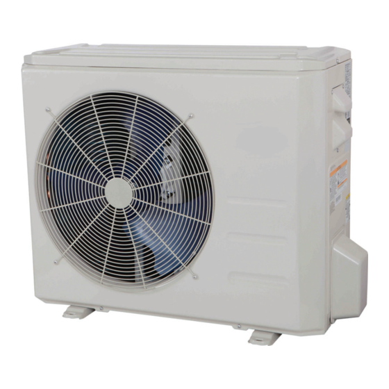
38MA*R
Outdoor Unit Single Zone Ductless System
Sizes 09 to 36
NOTES:
Read the entire instruction manual before starting the
installation.
Images are for illustration purposes only. Actual models may
differ slightly.
Installation Instructions
TABLE OF CONTENTS
. . . . . . . . . . . . . . . . . . . . . . . . . . . . . . . . . . . . . . .
. . . . . . . . . . . . . . . . . . . . . . . . . . . . . . . . . . . . . . . . . . .
. . . . . . . . . . . . . . . . . . . . . . . . . . . . . . . .
. . . . . . . . . . . . . . . . . . . . . . . . . . . . . . .
. . . . . . . . . . . . . . . . . . . . . . . . . . . . . . . . . . . . . . . .
. . . . . . . . . . . . . . . . . . . . . . . . . . . . . .
. . . . . . . . . . . . . . . . . . . . . . . . .
. . . . . . . . . . . . . . . . . . . . . . . . . . .
. . . . . . . . . . . . . . . . . . . . . . . . . .
. . . . . . . . . . . . . . . . . . . . . . . . .
. . . . . . . . . . . . . . . . . . . . .
. . . . . . . . . . . . . . . . . . . . . . . . .
. . . . . . . . . . . . . . . . . . .
PAGE
2
3
4
5
6
6
8
8
10
10
10
12
12
Advertisement
Table of Contents

Related Manuals for Carrier 38MAQB09R-1


Summary of Contents for Carrier 38MAQB09R-1
-
Page 1: Table Of Contents
38MA*R Outdoor Unit Single Zone Ductless System Sizes 09 to 36 Installation Instructions TABLE OF CONTENTS PAGE SAFETY CONSIDERATIONS ......PARTS LIST . -
Page 2: Safety Considerations
SAFETY CONSIDERATIONS Installing, starting up, and servicing air−conditioning equipment WARNING can be hazardous due to system pressures, electrical components, and equipment location (roofs, elevated structures, etc.). Only trained, qualified installers and service mechanics should ELECTRICAL SHOCK HAZARD install, start−up, and service this equipment. Failure to follow this warning could result in personal Untrained personnel can perform basic maintenance functions such injury or death. -
Page 3: Parts List
PARTS LIST Table 1—Parts List Part No. Part Name Qty. Outdoor unit Literature package including installation instructions and warranty Grommet to help fix the outdoor unit (helps with vibration prevention during operation) Drain Joint Drain Hose ■ Outdoor Fig. 1 - Parts List NOTES: If the outdoor unit is higher than the indoor unit, prevent rain from flowing into the indoor unit along the connection pipe by making a downward arc in the connection pipe before it enters the wall to the indoor unit. -
Page 4: System Requirements
SYSTEM REQUIREMENTS Allow sufficient space for airflow and service of the unit. See Fig. 3 for the required minimum distances between the unit, walls or ceilings. Piping IMPORTANT: Both refrigerant lines must be insulated separately. S Table 3 contains piping information for the product covered within this document. Table 3—Piping And Refrigerant Information 38MAR SIZE (208/230V) -
Page 5: Wiring
WIRING All wires must be sized per NEC (National Electrical Code) or CAUTION CEC (Canadian Electrical Code) and local codes. Use Electrical Data table MCA (minimum circuit amps) and MOCP (maximum EQUIPMENT DAMAGE HAZARD over current protection) to correctly size the wires and the disconnect fuse or breakers respectively. -
Page 6: Dimensions − Outdoor
DIMENSIONS − OUTDOOR A150731 Fig. 2 - Outdoor Unit Table 4—Unit Sizes 38MAR UNIT SIZE Voltage 115V 115V 208/230V 208/230V 208/230 V 208/230 V 208/230 V 208/230 V Height (H) in (mm) 21.81(554) 21.81(554) 21.81(554) 21.81(554) 23.90(607) 31.89(810) 31.89(810) 31.89(810) Width (W) in (mm) 32.09(815) - Page 7 CLEARANCES − OUTDOOR (CONT) Fig. 4 - Clearances for multiple units...
-
Page 8: Installation Tips
INSTALLATION TIPS Ideal installation locations include: 4. Remove all the burrs from the cut cross section of the pipe avoiding any burrs inside the tubes. Outdoor Unit S A location which is convenient to installation and not exposed to 5. Remove the flare nuts attached to the indoor and outdoor units. - Page 9 INSTALL ALL POWER AND INTERCONNECTING DRAIN CONNECTIONS WIRING TO OUTDOOR UNITS Install drains must meet local sanitation codes. 1. Mount outdoor power disconnect. Install the outdoor unit drain joint 2. Run power wiring from main box to disconnect per NEC Fit the seal into the drain joint, then insert the drain joint into the and local codes.
-
Page 10: Electrical Data
ELECTRICAL DATA Table 9—Electrical Data MAR OUTDOOR UNIT SIZE Volts-PH-Hz 115-1-60 115-1-60 208/230-1-60 208/230-1-60 208/230-1-60 208/230-1-60 208/230-1-60 208/230-1-60 Max – Min* 126-104 126-104 253-187 253-187 253-187 253-187 253-187 253-187 Oper. Voltage Power Supply Max Fuse/ CB AMP Volts-PH-Hz 115-1-60 115-1-60 208/230-1-60 208/230-1-60 208/230-1-60... -
Page 11: System Vacuum And Charge
SYSTEM VACUUM AND CHARGE 5000 CAUTION 4500 4000 LEAK IN UNIT DAMAGE HAZARD 3500 SYSTEM 3000 Failure to follow this caution may result in equipment damage or improper operation. 2500 2000 Never use the system compressor as a vacuum pump. VACUUM TIGHT 1500 TOO WET... -
Page 12: Start−Up
START−UP Test Operation Perform test operation after completing gas leak and electrical safety check. See the indoor unit installation instructions and owner’s manual for additional start up information. SYSTEM CHECKS 1. Conceal the tubing where possible. 2. Make sure that the drain tube slopes downward along its entire length. 3.
Need help?
Do you have a question about the 38MAQB09R-1 and is the answer not in the manual?
Questions and answers