
Related Manuals for Sorel AIR TDC


Summary of Contents for Sorel AIR TDC
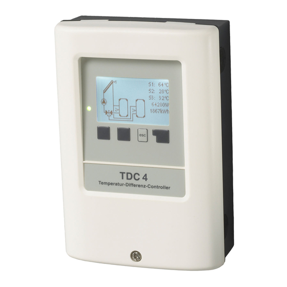
- Page 1 Temperature Difference Controller AIR TDC Installation and operating instructions Read carefully before installation, commissioning and operation...
-
Page 2: Table Of Contents
Content Settings Safety instruction 5.1. Tmin Collector A.1. EC declaration of conformity 5.2. Tset Room A.2. General instructions 5.3. Collector / Room A.3. Explanation of symbols 5.4. Tset Room A.4. Changes to the unit 5.8. Collector / Room A.5. Warranty and liability 5.20. -
Page 3: Safety Instruction
EC declaration of conformity By affi xing the CE mark to the unit the manufacturer declares that the Temperature- Difference-Controller AIR TDC , conforms to the following relevant safety regulations: EC low voltage directive 2006/95/EC EC electromagnetic compatibility directive 2004/108/EC Conformity has been verifi ed and the corresponding documentation and the EC declaration of conformity are kept on fi le by the manufacturer. -
Page 4: Changes To The Unit
Safety instructions A.4. Changes to the unit Changes to the unit can compromise the safety and function of the unit or the entire system. Danger • Changes, additions to or conversion of the unit are not permitted without the writ- ten permission from the manufacturer •... -
Page 5: Specifications
Description of controller B.1. Specifications Electrical specifications: Mains voltage 230VAC +/- 10 % Mains frequency 50 - 60 Hz Power consumption 1,5 W - 2,3 W Internal fuse T2A / 250V slow blow Protection category IP40 Protection class Overvoltage Category Degree of Pollution Category mechanical relay 460VA for AC1 / 460W for AC3 2 (R1 - R2) 0-10V output, tolerance 10 %, 10 k Ω... -
Page 6: About The Controller
The controller menu contains headwords for the measured values and settings, as well as help texts or clearly-structured graphics. The AIR TDC can be used as a temperature difference controller for the various sys- tem variants illustrated and explained under B.5. -
Page 7: Hydraulic Variants
Description of controller B.6. Hydraulic variants The following illustrations should be viewed only as schematic diagrams showing the respective hydraulic systems, and do not claim to be complete. The controller does not replace safety devices under any circumstances. Depending on the specifi c application, additional system components and Caution safety components may be mandatory, such as check valves, non-return valves, safety temperature limiters, scalding protectors, etc., and must... -
Page 8: Installation
Installation C.1. Wall installation Install the controller only in dry areas and under the ambient conditions de- scribed under B.1 “Specifi cations”. Carry out the following steps 1-8. Caution 1. Unscrew cover screw completely C.1.1 2. Carefully pull upper part of housing from lower part. -
Page 9: Electrical Connection
Installation C.2. Electrical connection Before working on the unit, switch off the power supply and secure it against being switched on again! Check for the absence of power! Electrical connections may only be made by a specialist and in compli- Danger ance with the applicable regulations. -
Page 10: Installing The Temperature Sensors
Installation 1.Select necessary program/hydraulics C.2.1 (Fig. B5) 2.Open controller as described under C.1. 3.Strip cables by 55 mm max., insert, fi t the strain relief devices, strip the last 8 - 9mm of the wires (Fig. C.2.1) 4.Open the terminals using a suitable screwdriver (Fig. -
Page 11: Terminal Connection Diagram
Installation D. - Terminal connection diagram max. 12V Netzseite 230VAC Gefahr Achtung Low voltage max. 12VAC/DC Mains voltage 230VAC 50-60Hz Terminal: Connection for: Terminal: Connection for: S1 (2x) Sensor 1 Ventilator S2 (2x) Sensor 2 Neutral conductor N S3 (2x) Sensor 3 Ventilator fl ap Neutral conductor N... -
Page 12: Operation
Operation E.1. Display and input The display (1), with its extensive text and graphics mode, is almost self-explanatory, allowing easy operation of the controller. The LED (2) lights up green when a relay is switched on. The LED (2) lights up red when operating mode “Off”... -
Page 13: Commissioning Help
Parametrisation E.2. Commissioning help The fi rst time the controller is turned on and after the language and time are set, a query appears as to whether you want to parametrise the controller using the commissioning help or not. The commis- sioning help can also be terminated or called up again at any time in the special functions menu. -
Page 14: Menu Sequence And Menu Structure
Operation E.4. Menu sequence and menu structure The graphics or overview mode appears when no key has been press for 2 min- utes, or when the main menu is exited by pressing “esc“. Pressing a key in graphics or overview mode takes you directly to the main menu. -
Page 15: Measurement Values
Measurement values 1. - Measurement values The menu “1. Measurement values” serves to display the currently measured temperatures. The menu is closed by pressing “esc” or selecting “Exit measurement values”. Selecting “Info” leads to a brief help text explaining the measurement values. Selecting “Overview”... -
Page 16: Statistics
Statistics 2. - Statistics The menu “2. Statistics” is used for func- tion control and long-term monitoring of the system. The menu is closed by pressing “esc” or selecting “Exit statistics”. For analysis of the system data it is essential for the time to be set ac- curately on the controller. -
Page 17: Display Mode
Display mode 3. - Display mode Menu “3. Display mode” is used to define the controller’s display for normal opera- tion. This display appears whenever two min- utes go by without any key being pressed. The main menu appears again when a key is pressed. -
Page 18: Operating Modes
Operating modes 4. - Operating modes In menu “4. Operating modes” the con- troller can either be placed in automatic mode, switched off, or placed in a manual operating mode. The menu is closed by pressing “esc” or selecting “Exit operating modes”. 4.1. -
Page 19: Settings
Settings 5. - Settings The necessary basic settings required for the control function are made in menu “5. Settings”. This does not under any circumstances replace the safety facilities to be provided by the customer! Caution The menu is closed by pressing “esc” or select- ing “Exit settings”. -
Page 20: Tset Room
Settings 5.4. - Tset Room Switch-off temperature at sensor 2 If this value is exceeded at the room sensor S2, the controller switches the vebntialtior off. If the temperature falls below this value again and the other conditions are also met, then the controller switches the ventilator on again. Temperature values that are set too high can lead to scalding or damage to the system. -
Page 21: Protective Functions
Protective functions 6. - Protective functions Menu “6. Protective functions” can be used to activate and set various protective functions. This does not under any circumstances replace the safety facilities to be provided by the customer! Caution The menu is closed by pressing “esc” or select- ing “Exit settings”. -
Page 22: Special Functions
Special functions 7. - Special functions Menu “7. Special functions” is used to set basic items and expanded functions. Other than the time all settings may only be made by a specialist. Caution The menu is closed by pressing “esc” or select- ing “Exit special functions”. -
Page 23: Speed Control V1
Special functions 7.2.1.1. - Speed when „On“ 7.3. - Speed control This menu determines the calculated and displayed speed of the pump. If e.g. 30% is set here and the signal set in „PWM on/0-10V on“ is put out, 30% speed is displayed. When the signal set in „PWM max/0-10V max“... -
Page 24: Max. Speed
Special functions 7.3.4. - max. speed The maximum speed of the ventilator is specifi ed here. During the setting the ventilator runs at the specifi ed speed and the fl ow rate can be determined. The indicated percentages are guide values that may vary to a greater or lesser extent depending on the system, ventilator and ventilator stage. -
Page 25: Factory Settings
Special functions 7.7. - Factory settings All of the settings that have been made can be reset, thus returning the controller to its delivery state. The entire parametrisation, analyses, etc. of the controller will be lost irrevocably. The controller must then be commissioned once again. Caution 7.8. -
Page 26: Menu Lock
Menu lock 8. - Menu lock Menu “8. Menu lock” can be used to secure the controller against unintentional changing of the set values. The menu is closed by pressing “esc” or select- ing “Exit menu lock”. The menus listed below remain completely accessible despite the menu lock being activated, and can be used to make adjustments if necessary: Measurement values Analysis... - Page 27 Service values 9. - Service values The menu “9. Service values” can be used for remote diagnosis by a specialist or the manu- facturer in the event of an error, etc. Enter the values at the time when the error occurs e.g. in the table. Caution The menu can be closed at any time by press- ing “esc”.
-
Page 28: Language
Language 10. - Language Menu “10. Language” can be used to se- lect the language for the menu guidance. This is queried automatically during initial commissioning. The choice of languages may differ, however, depending on the device design. Language selection is not available in every device design! -
Page 29: Malfunctions
Malfunctions Z.1. Malfunctions with error messages If the controller detects a malfunction, the red light fl ashes and the warning symbol also appears in the display. If the error (LED fl ashes + is no longer present, the warning symbol warning symbol) changes to an info symbol and the red light no longer fl ashes. -
Page 30: Replacing The Fuse
Malfunctions Z.2. Replacing the fuse Repairs and maintenance may only be performed by a specialist. Before working on the unit, switch off the power supply and secure it against Danger being switched on again! Check for the absence of power! Only use the supplied spare fuse or a fuse of the same design with the following specifi cations: T2A / 250V Danger... - Page 31 Tips & Tricks The service values (see 9.) include not only current measurement values and operating states, but also all of the settings for the controller. Write the service values down just once after commissioning has been successfully completed. In the event of uncertainty as to the control response or malfunctions the service values are a proven and successful method for remote diagnosis.
- Page 32 Hydraulic variant set: Commissioned on: Commissioned by: Final declaration: Although these instructions have been created with the greatest possi- ble care, the possibility of incorrect or incomplete information cannot be excluded. Subject as a basic principle to errors and technical changes. Your specialist dealer:...
Need help?
Do you have a question about the AIR TDC and is the answer not in the manual?
Questions and answers