Table of Contents
Advertisement
Quick Links
Advertisement
Table of Contents

Related Manuals for TW Audio VERARF600i


Summary of Contents for TW Audio VERARF600i
- Page 1 Assembly VERA RF600i Instructions...
- Page 2 If you lend your product to another party, inform that party of the safety-related operating pro- cedures and hand over this assembly guide. If you require additional copies of this manual, you can obtain them free of charge from TW AUDiO or download them from www.twaudio.de Instructions in this setup manual Strictly adhere to the instructions contained in this assembly guide that are marked as follows: This symbol in combination with the signal word “Warning”...
- Page 3 Quality warranties or assurance of suitability for a certain type of use based on the technical specifications, dimensions and weights are not granted by TW AUDiO. TW AUDiO also shall not assume liability for any secondary damage (property damage and/ or personal injury) nor for the failure to comply with this assembly guide! TW AUDiO reserves the right to update this document based on recent developments.
-
Page 4: Table Of Contents
VERA RF600i Assembly Instructions Content 1. Safety | Intended use ...................... 5 2. Overview ........................7 Scope of delivery ..................... 7 3. Technical specifications ....................8 Data sheet ....................... 8 4. Commissioning ....................... 9 Setup ........................9 Necessary tools for setting up the flown system ............9 Using the VERA LA900i load adapter in flown systems ........... -
Page 5: Safety | Intended Use
Note the operating modes described in this operating manual. Other uses are not permis- sible. Damage caused by improper use is not covered by TW AUDiO. Before each installation, check the integrity of the VERA RF600i rigging frame and ensure that all components are in perfect condition. - Page 6 Whenever you make changes to the flown system, always use new cylinder screws (Item 2) and lock washers (Item 3) as delivered with the product. These items are available from TW AUDiO. WARNING When working with heavy loads exceeding 20 kg (44 lbs.), use suitable aids (dollies, hoisting slings, etc.).
-
Page 7: Overview
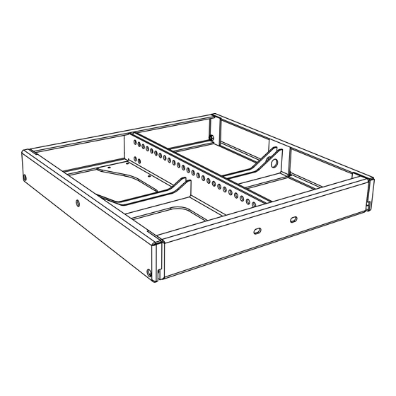
VERA RF600i Assembly Instructions 2. Overview Scope of delivery Figure 2.1 – Overview VERA RF600i rigging frame – powder-coated surface ..........1 pc Cylinder screws M8 x 16-12.9 ................7 pcs Locking washer VS-8-1.4301 ................7 pcs Front rigging end plate – powder-coated surface ..........4 pcs Middle rigging end plate –... -
Page 8: Technical Specifications
VERA RF600i Assembly Instructions 3. Technical specifications Data sheet 600 kg, with safety factor 10 against breakage. Maximum load capacity This corresponds to e.g. 24x VERA20i or 12x VERA S17i units. Dimensions (h x w x d) 80 x 600 x 600 mm (3.1 x 23.6 x 23.6 in) Weight 16,7 kg (36 lbs) Surface... -
Page 9: Commissioning
4. Commissioning Setup The VERA RF600i rigging frame is designed both for hanging operation. TW AUDiO provides a wide range of accessories to securely attach the rigging frame. TW AUDiO recommends using only the accessories specified by TW AUDiO for securing and mounting the rigging frame. -
Page 10: Using The Vera La900I Load Adapter In Flown Systems
VERA RF600i Assembly Instructions Using the VERA LA900i load adapter in flown systems Figure 4.3.1 – VERA LA900i load adapter Attach the VERA LA900i load adapter to the VERA RF600i rigging frame as shown in figure 4.3.2! Use items 7, 8 and 9 from the scope of delivery (see figure 2.1). WARNING Figure 4.3.2 –... - Page 11 VERA RF600i Assembly Instructions Use the EASE Focus simulation software to design system setups with the VERA RF600i rig- ging frame as well as the associated VERA20i and / or VERA S17i loudspeakers. The simula- tion can be used to determine the correct pin points for your application. NOTE The VERA LA900i load adapter’s design allows for four different usage scenarios.
- Page 12 VERA RF600i Assembly Instructions 18 17 16 15 14 13 12 Figure 4.3.5 - VERA LA900i load adapter at pin point 16 – reverse orientation Inserting the two screws into 15 and 16 will result in 16 as pin point for the backward-facing VERA LA900i load adapter.
-
Page 13: Secondary Safety Component In The Flown System
VERA RF600i Assembly Instructions Secondary safety component in the flown system Figure 4.4.1 – Secondary safety component example Please obtain about regulations of secondary safety components in the place where you wish to operate the system. NOTE Attach a second, separate safety component to the “for safety wire” points D and E. This can be safety chains for example. -
Page 14: Wind Load In The Flown System
VERA RF600i Assembly Instructions Wind load in the flown system Before setting up the system outdoors, consider unforeseeable wind conditions at the ope- ration site! Disassemble your system immediately when wind forces exceed 8 bft (34 to 40 kn – WARNING 38.5 to 46 mph)! Make sure that there are no persons in the close proximity of the flown system! -
Page 15: Angle Settings In A Flown System
VERA RF600i Assembly Instructions Angle settings in a flown system 1. Attach the bracket (see figure 4.6.1) as described in the angle settings table (see figure 4.6.2). The bracket comes with the VERA20i loudspeaker (position 5 of the scope of deli- very) and the VERA S17i loudspeaker (position 4 of the scope of delivery). - Page 16 VERA RF600i Assembly Instructions 0,3° 0° 0,8° 1,5° 2,4° 3,5° 4,9° 6,8° 9,1° 12° Figure 4.6.4 – Detail views of the angle settings from figure 4.6.3...
-
Page 17: Installation Position Of The Lock Washer
VERA RF600i Assembly Instructions Installation position of the lock washer Make sure that the lock washers (item 3 on the scope of delivery) are installed as shown in figure 4.7.1! Reverse installation of the lock washer would cause the lock washer to have no biasing force WARNING and accordingly lose its effect! Figure 4.7.1 –... -
Page 18: Preparing The First Vera20I Loudspeaker For A Flown System
VERA RF600i Assembly Instructions Preparing the first VERA20i loudspeaker for a flown system 1. Start by attaching splay links on the front top left and right of the VERA20i loudspeaker (item 4 on the scope of delivery). 2. Attach each splay link using one cylinder screw, item 2 and one lock washer, item 3 from WARNING the VERA20i loudspeaker scope of delivery. - Page 19 VERA RF600i Assembly Instructions 10. Attach splay links on the front bottom left and right of the VERA20i loudspeaker (item 4 on the scope of delivery). 11. Attach each splay link using one cylinder screw, item 2 and one lock washer item 3 from WARNING the VERA20i loudspeaker scope of delivery.
-
Page 20: Setting Up The First Vera20I Loudspeaker In A Flown System
VERA RF600i Assembly Instructions Setting up the first VERA20i loudspeaker in a flown system To set up a flown system with the VERA20i loudspeakers, proceed as follows: 1. Please note that setting up the VERA RF600i rigging frame always requires two persons! WARNING 2. - Page 21 VERA RF600i Assembly Instructions 8. Swivel the VERA20i loudspeaker until the brackets meet the rigging frame and you can secure the loudspeaker to the hole marked with N. 9. Use one cylinder screw, item 1 and one lock washer, item 2 from the VERA20i loudspeaker WARNING scope of delivery for attaching the brackets to the VERA RF600i rigging frame.
- Page 22 VERA RF600i Assembly Instructions 12. Tighten all screws on the left and right side of the VERA20i loudspeaker and the VERA RF600i rigging frame. (torque: 20 Nm) WARNING Figure 4.9.3 – Attachment of the first VERA20i loudspeaker at the VERA RF600i rigging frame...
-
Page 23: Preparing The Following Vera20I Loudspeakers For A Flown System
VERA RF600i Assembly Instructions 4.10 Preparing the following VERA20i loudspeakers for a flown system 1. Start by attaching splay links on the front bottom left and right of the VERA20i loudspeaker (item 4 on the scope of delivery). 2. Attach each splay link using one cylinder screw, item 2 and one lock washer, item 3 from WARNING the VERA20i loudspeaker scope of delivery. -
Page 24: Setting Up The Following Vera20I Loudspeakers In A Flown System
VERA RF600i Assembly Instructions 4.11 Setting up the following VERA20i loudspeakers in a flown system Continue to set up the VERA20i loudspeaker system for rigging as follows: 1. Please note that setting up the VERA RF600i rigging frame always requires two persons! WARNING 2. - Page 25 VERA RF600i Assembly Instructions 7. Swivel each VERA20i loudspeaker until the brackets meet the loudspeaker and you can secure the loudspeaker using the hole previously determined in the EASE Focus simulation software. WARNING 8. Attach all loudspeakers to the flown system using two cylinder screws, item 2 and two lock washers, item 3 from the VERA20i loudspeaker scope of delivery.
- Page 26 VERA RF600i Assembly Instructions 11. T ighten all screws on the left and right side of the VERA20i loudspeaker. (torque: 20 Nm) WARNING Figure 4.11.3 – Attachment of the following VERA20i loudspeakers 12. Follow the instructions in this section of the manual to connect up to 24 VERA20i loudspeakers. 13.
-
Page 27: Preparing The Last Vera20I Loudspeaker For A Flown System
VERA RF600i Assembly Instructions 4.12 Preparing the last VERA20i loudspeaker for a flown system 1. Start by attaching the rigging end plates (item 4 on the VERA RF600i scope of delivery) to the VERA20i loudspeaker on the front bottom left and right. 2. -
Page 28: Setting Up The Last Vera20I Loudspeaker In A Flown System
VERA RF600i Assembly Instructions 4.13 Setting up the last VERA20i loudspeaker in a flown system Continue to set up the VERA20i loudspeaker system as follows: 1. Please note that setting up the VERA RF600i rigging frame always requires two persons! WARNING 2. - Page 29 VERA RF600i Assembly Instructions 8. Swivel the last VERA20i loudspeaker until the brackets meet the loudspeaker and you can secure the last loudspeaker using the hole previously determined in the EASE Focus simulation. WARNING 9. Attach the loudspeaker to the flown system using two cylinder screws, item 2 and two lock washers, item 3 from the VERA20i loudspeaker scope of delivery.
-
Page 30: Preparing A Vera S17I Loudspeaker For A Flown System
VERA RF600i Assembly Instructions 4.14 Preparing a VERA S17i loudspeaker for a flown system 1. Start by attaching splay links on the front top left and right of the VERA S17i loudspeaker (item 1 on the scope of delivery). Please note that the VERA S17i loudspeakers for the cardioid application have to be according to chapter 4.19. -
Page 31: Setting Up The Vera S17I Loudspeaker In A Flown System
VERA RF600i Assembly Instructions 4.15 Setting up the VERA S17i loudspeaker in a flown system To set up the flown system with the VERA S17i loudspeaker, proceed as follows: 1. Please note that setting up the VERA S17i loudspeaker always requires two persons! WARNING 2. - Page 32 VERA RF600i Assembly Instructions 1. Place the VERA S17i loudspeaker already screwed to the VERA RF600i rigging frame at the lower VERA S17i loudspeaker. 2. Insert the splay links and the brackets of the lower VERA S17i loudspeaker into the WARNING openings provided on the upper VERA S17i loudspeaker.
- Page 33 VERA RF600i Assembly Instructions 1. Tighten all screws on the left and right side of the VERA S17i loudspeaker. (torque: 20 Nm) WARNING Figure 4.15.3 - Attachment of the following VERA S17i loudspeakers 2. Follow the instructions in this section to connect up to twelve VERA S17i loudspeakers. 3.
-
Page 34: Preparing The Last Vera S17I Loudspeaker For A Flown System
VERA RF600i Assembly Instructions 4.16 Preparing the last VERA S17i loudspeaker for a flown system 1. Start by attaching the front rigging end plates at the front left and right of the VERA S17i loudspeaker (item 4 on the scope of delivery). 2. -
Page 35: Setting Up The Last Vera S17I Loudspeaker In A Flown System
VERA RF600i Assembly Instructions 4.17 Setting up the last VERA S17i loudspeaker in a flown system Continue to set up of the VERA S17i loudspeaker system as follows: 1. Please note that setting up the VERA S17i loudspeaker system always requires two persons! WARNING 2. - Page 36 VERA RF600i Assembly Instructions 1. Tighten all screws on the left and right side of the VERA S17i loudspeaker. (torque: 20 Nm) WARNING Figure 4.17.2 - Attachment of the last VERA S17i loudspeaker...
-
Page 37: Setting Up The Vera20I And Vera S17I Loudspeaker In A Flown System
VERA RF600i Assembly Instructions 4.18 Setting up the VERA20i and VERA S17i loudspeaker in a flown system To set up the flown system with VERA20i and VERA S17i loudspeakers, proceed as follows: 1. Please note that setting up the loudspeaker system always requires two persons! WARNING 2. - Page 38 VERA RF600i Assembly Instructions 1. Tighten all screws on the left and right side of the VERA20i and VERA S17i loudspeakers. (torque: 20 Nm) WARNING Figure 4.18.2 - Attachment of the mixed system setup...
-
Page 39: Cardioid Application Of The Vera S17I Loudspeaker In A Flown System
VERA RF600i Assembly Instructions 4.19 Cardioid application of the VERA S17i loudspeaker in a flown system To set up the flown system with the VERA S17i loudspeakers for the cardioid application, proceed as follows: 1. Please note that setting up the VERA S17i loudspeaker system always requires two persons! WARNING 2. - Page 40 VERA RF600i Assembly Instructions 1. Insert the front splay links and the rear splay links of the twisted VERA S17i loudspeaker to the openings of the VERA S17i loudspeaker. 2. Attach the loudspeaker in the flown cardioid system using for the left and right side two WARNING cylinder screws, item 2 and two lock washers, item 3 from the VERA S17i loudspeaker scope of delivery.
- Page 41 VERA RF600i Assembly Instructions 1. Tighten all screws on the left and right side of the VERA S17i loudspeaker. (torque: 20 Nm) WARNING Figure 4.19.3 - Attachment of the cardioid system setup...
- Page 42 VERA RF600i Assembly Instructions 1. Additional front grills with mounting screws for a uniform appearance of the cardioid sys- tem setup with VERA S17i loudspeakers are available at TW AUDiO. NOTE Figure 4.19.4 - Attachment of an optional front grill 2.
-
Page 43: Rigging Tracks
VERA RF600i Assembly Instructions 4.20 Rigging tracks Only mount the VERA20i loudspeakers when all VERA S17i loudspeakers are mechanically connected to the VERA RF600i rigging frame through the front and the middle rigging tracks. Make sure that the load is never transferred from one rigging track to another rigging track WARNING through the speaker enclosure. -
Page 44: Transport And Storage
VERA RF600i Assembly Instructions 5. Transport and Storage Ensure that the surface of the rigging frame is not damaged during transport and storage. Moisture may penetrate where steel surfaces are exposed by scratches and result in corro- sion. NOTE This is why the product should be transported in a safe, careful, dry and largely dust-free manner. -
Page 45: Ce Declaration Of Conformity
VERA RF600i Assembly Instructions 6. CE Declaration of Conformity Copy and translation of the original CE Conformity Declaration: We hereby declare that the below-referenced components by virtue of their design and con- struction, and in the configuration placed on the market by us, satisfy the safety and health requirements of the applicable EC directives. - Page 46 VERA RF600i Assembly Instructions TW AUDiO GmbH Osterholzallee 140 71636 Ludwigsburg Germany Phone : + 49 (0) 71 41-48 89 89 0 Fax: + 49 (0) 71 41-48 89 89 99 E-Mail: info@twaudio.de WWW: www.twaudio.de...
Need help?
Do you have a question about the VERARF600i and is the answer not in the manual?
Questions and answers