TESTO 512 Instruction Manual
Digital manometer
Hide thumbs
Also See for 512:
- Instruction manual (20 pages) ,
- Instruction manual (20 pages) ,
- Instruction manual (60 pages)
Table of Contents
Advertisement
Quick Links
Find Quality Products Online at:
Instruction manual
General notes ....................................................22
1.
Safety advice .....................................................23
2.
Intended purpose ...............................................24
3.
Product description ............................................25
3.1
Display and control elements ........................................ 25
3.2
Interfaces ..................................................................... 26
3.3
Voltage supply .............................................................. 26
4.
Commissioning ..................................................27
5.
Operation ...........................................................28
5.1
Connecting pressure hoses, Pitot tube ......................... 28
5.2
Switching the instrument on / off .................................. 29
5.3
Switching the display light on / off ................................ 29
5.4
Performing settings ...................................................... 29
6.
Measuring ..........................................................34
7.
Care and maintenance .......................................36
8.
Questions and answers ......................................37
9.
Technical data ...................................................38
10. Accessories/spare parts.....................................39
GlobalTestSupply
www.
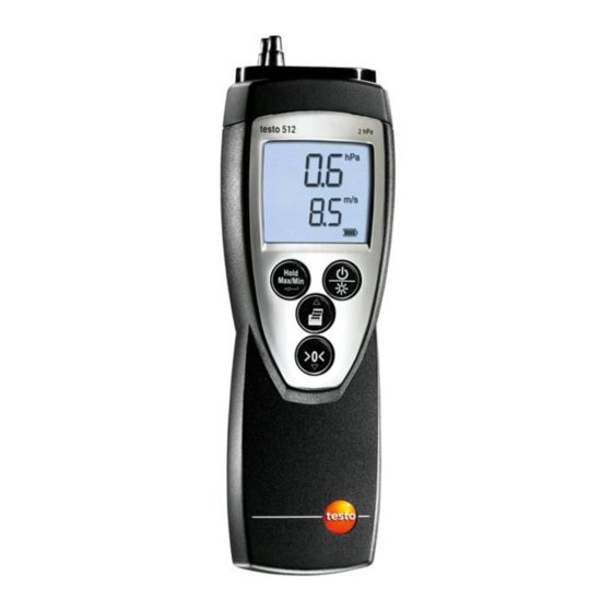
testo 512
Digital manometer
en
Contents
.com
sales@GlobalTestSupply.com
Advertisement
Table of Contents

Subscribe to Our Youtube Channel
Related Manuals for TESTO 512


Summary of Contents for TESTO 512
-
Page 1: Table Of Contents
512 Digital manometer Instruction manual Contents General notes ............22 Safety advice .............23 Intended purpose ..........24 Product description ..........25 Display and control elements ........25 Interfaces ..............26 Voltage supply .............. 26 Commissioning ..........27 Operation ............28 Connecting pressure hoses, Pitot tube ......28 Switching the instrument on / off ........ -
Page 2: General Notes
General notes General notes This chapter provides important advice on using this documentation. The documentation contains information that must be applied if the product is to be used safely and efficiently. Please read this documentation through carefully and familiarise yourself with the operation of the product before putting it to use. -
Page 3: Safety Advice
Take faulty rechargeable batteries/spent batteries to the collection points provided for them. Send the product back to Testo at the end of its useful life. We will ensure that it is disposed of in an environmentally friendly manner. -
Page 4: Intended Purpose
Use the product only for those applications for which it was designed. Ask Testo if you are in any doubt. The testo 512 is a compact digital manometer with temperature compensation for measuring the positive and negative over-pressure and differential pressure of non- aggressive gases. -
Page 5: Product Description
3. Product description 25 Product description This chapter provides an overview of the components of the product and their functions. 3.1 Display and control elements Overview Infrared interface, Pressure connection nipple (4/6mm): (+) positive over-pressure (-) negative over-pressure Display ... -
Page 6: Interfaces
Print function: Readings are sent to the printer 3.2 Interfaces Infrared interface Measurement data can be sent to a Testo printer via the infrared interface on the head of the instrument. Pressure connection nipple Pressure hoses can be connected via the pressure connection nipple at the upper end of the instrument. -
Page 7: Commissioning
4. Commissioning 27 Commissioning This chapter describes the steps required to commission the product. Removing the protective film on the display: Pull the protective film off carefully. Inserting a battery/rechargeable battery: To open the battery compartment on the rear of the instrument, push the lid of the battery compartment in the direction of the arrow and remove it. -
Page 8: Operation
5. Operation Operation This chapter describes the steps that have to be executed frequently when using the product. 5.1 Connecting pressure hoses, Pitot tube Connecting pressure hoses: Attach the pressure hoses (4 or 6mm) correctly according to the mathematical signs: ·... -
Page 9: Switching The Instrument On / Off
5. Operation 29 5.2 Switching the instrument on / off Switching the instrument on: Press - A segment test is carried out: The measurement value display segments light up briefly (2x 8888). - Measurement view is opened: The current reading is displayed. - Page 10 5. Operation Setting the unit of pressure: The configuration modus is open, the set unit blinks. Set the desired unit with and confirm with Setting the parameter for the lower measurement value line: The parameters temperature (internal temperature sensor) or flow (versions 2hPa, 20hPa and 200hPa only) can be displayed in the lower measurement value line.
- Page 11 5. Operation 31 Select the desired option with and confirm with · On: The flow measurement value is displayed in the lower measurement value line · OFF: The flow measurement value is not displayed in the lower measurement value line OFF is selected: Next handling objective ...
- Page 12 5. Operation Setting max/min pressure function: The configuration modus is open, MaxMin lights up Select the desired option with and confirm with · · On: When printing current or recorded measurement values, maximum and minimum values of the parameters pressure and flow (versions 2hPa, 20hPa und 200hPa only) are also printed out.
- Page 13 5. Operation 33 To set the date/time: Configuration mode is opened, Year is lit. to set the current year and confirm with to set the other values for the month (Month), day (Day) and time (Time) and confirm each one with ...
-
Page 14: Measuring
6. Measuring Measuring This chapter describes the steps that are required to perform measurements with the product. T aking a measurement: The instrument is switched on and is in measurement view. Place the measuring instrument in the position in which the measurement is to be made (Usage position). - Page 15 - All maximum or minimum values are reset to the current reading. Printing readings: A Testo printer is required (accessory part). When printing current or recorded measurement values, maximum and minimum values of the parameters pressure and flow (versions 2hPa, 20hPa und 200hPa only) are also printed out.
-
Page 16: Care And Maintenance
7. Care and maintenance Care and maintenance This chapter describes the steps that help to maintain the functionality of the product and extend its service life. C leaning the housing: Clean the housing with a moist cloth (soap suds) if it is dirty. -
Page 17: Questions And Answers
8. Questions and answers 37 Questions and answers This chapter gives answers to frequently asked questions. Question Possible causes Possible solution is lit (bottom right · Instrument battery is · Replace instrument in display). almost spent. battery. Auto Off Instrument switches ·... -
Page 18: Technical Data
9. Technical data Technical data Characteristic Value All Versions: Measurement parameters Pressure (hPa, kPa, psi, inH O, mmHg, inHg, mmH Versions 2hPa, 20hPa, 200hPa only: Pa) Temperature (°C, °F) Versions 2hPa, 20hPa, 200hPa only: Flow (m/s, fpmx100) Measuring range 0...+60 °C / 32...+140°F temperature Resolution 0.1°C, 0.1°F... -
Page 19: Accessories/Spare Parts
Pitot tube, 350mm 0635 2145 Hose connection set incl. silicon hose 0554 0315 TopSafe testo 512, protection from dirt and knocks 0516 0221 Testo report printer with IRDA and infrared interface 1 roll thermo paper and 4 mignon batteries 0554 0547 GlobalTestSupply www.
Need help?
Do you have a question about the 512 and is the answer not in the manual?
Questions and answers