Advertisement
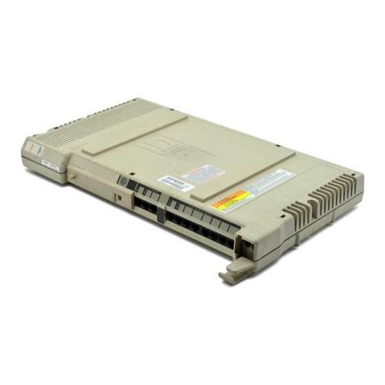
308EC Module
7-foot
Line Cords
308EC
Module
The instructions also apply to previous models of PARTNER, including the PARTNER, PARTNER PLUS,
and PARTNER II Communications Systems. Please note the illustrations are examples only. Your system
may look different.
Important Safety Instructions
!
WARNING:
The following list provides basic safety precautions that should always be followed when using your telephone
equipment:
1. Read and understand all instructions.
2. Follow all warnings and instructions marked on the equipment.
3. Unplug all telephone connections before cleaning. DO NOT use liquid cleaners or aerosol cleaners. Use a
damp cloth for cleaning.
4. The product should be serviced by (or taken to) a qualified repair center when service or repair work is
required.
5. DO NOT use the product near water, for example, a wet basement location.
6. Never push objects of any kind into the slots or openings as they may touch dangerous voltage points or short
out parts that could result in a risk of fire or electric shock. Never spill liquid of any kind on the equipment;
doing so may result in serious damage to the components.
7. DO NOT use the telephone to report a gas leak in the vicinity of the leak.
8. The telephone equipment is provided with a three-wire grounding type plug. This is a safety feature. DO NOT
defeat the safety purpose of the grounding type plug. DO NOT staple or otherwise attach the power supply
cord to building surfaces.
!
CAUTION:
DO NOT block or cover the ventilation slots and openings. They prevent the product from overheating.
DO NOT place the equipment in a separate enclosure unless proper ventilation is provided.
Additional Safety Instructions for Installation Personnel
1. Install the equipment to meet all the environmental and electrical requirements listed in the documentation
that came with your system.
2. DO NOT install equipment during a lightning storm.
3. DO NOT install telephone jacks in a wet location unless the jack is specifically designed for wet locations.
4. Never touch uninsulated telephone wires or terminals unless the telephone line has been disconnected at the
network interface.
5. Use caution when installing or modifying telephone lines.
6. The control unit must be securely wall mounted.
Expanding Your PARTNER
Communications System
This document provides instructions for adding or replacing modules in your
existing system. The modules you may add include:
T 308EC (For use on PARTNER ACS Release 2.0 or later only)
T PARTNER MAIL VS (PMVS)
T 400E, 400EC
T 200E
T 206, 206E, 206EC
SAVE THESE INSTRUCTIONS
Copyright 2000
All rights reserved.
Printed in U.S.A.
®
Advanced
518-456-500
Comcode 108873316
PARTNER is a registered trademark of
Avaya Inc.
Advertisement
Table of Contents

Related Manuals for Avaya Partner 308EC


Summary of Contents for Avaya Partner 308EC
- Page 1 5. Use caution when installing or modifying telephone lines. 6. The control unit must be securely wall mounted. SAVE THESE INSTRUCTIONS Copyright 2000 518-456-500 Comcode 108873316 All rights reserved. PARTNER is a registered trademark of Printed in U.S.A. Avaya Inc.
- Page 2 Using a 2-Slot Carrier IMPORTANT: The processor module must already be mounted on the wall. If it is not, refer to the documentation that came with your system. Remove the clear, plastic protector from the A) Before starting, remove the power cord If you are replacing the second module in a connector on the rear of the new module from the wall outlet.
- Page 3 Using a 5-Slot Carrier IMPORTANT: The 5-slot carrier and the processor module must already be mounted on the wall. If it is not, refer to the documentation that came with your system. On/Off Switch Power Jack MODULE Handle Screw A) Move the carrier’s On/Off switch to "Off," If you are removing an existing module, see if Before installing any modules, remove the and unplug the power cord from the wall...
- Page 4 Using a 5-Slot Carrier–continued Lights Screw A) To replace the carrier’s cover, grasp it by Check the green lights on the fronts of the modules: its upper edges and hold it squarely over the carrier. A) If a single light is out, power down the carrier, reseat the module, then power up the B) Place the cover over the modules and carrier.
Need help?
Do you have a question about the Partner 308EC and is the answer not in the manual?
Questions and answers