Table of Contents
Advertisement
Quick Links
Advertisement
Table of Contents

Subscribe to Our Youtube Channel
Related Manuals for L-Acoustics K2


Summary of Contents for L-Acoustics K2
- Page 1 owner's manual (EN)
- Page 2 Document reference: K2 owner's manual (EN) version 1.1 Distribution date: January 13, 2020 © 2020 L-Acoustics. All rights reserved. No part of this publication may be reproduced or transmitted in any form or by any means without the express written consent of the publisher.
-
Page 3: Table Of Contents
Additional subwoofer system........................33 K1-SB............................34 KS28............................37 SB28............................39 Additional downll element........................41 Kara............................41 Inspection and preventive maintenance....................... 42 How to do preventive maintenance......................42 Rigging part inspection........................... 43 Mechanical system overview........................43 K2 mixed array with K2-BAR, K2-BUMP, K1-SB, and K2-LINK............44... - Page 4 I - Attaching a block of four K2 under K2-RIGBAR................97 J - Attaching a block of four K2 under K2..................100 K - Attaching a block of four K2 under a K1 system element............106 L - Attaching K1 or K1-SB under K2-BUMP..................113 M - Mounting LA-RAK/LA-RAK II on K2-BUMP................
- Page 5 Specications..............................161 APPENDIX A: Pickup points guidelines......................181 APPENDIX B: Installing a laser inclinometer.......................185 APPENDIX C: Recommendation for speaker cables.................... 191...
-
Page 6: Safety
Respect the Working Load Limit (WLL) of third party equipment. L-Acoustics is not responsible for any rigging equipment and accessories provided by third party manufacturers. Verify that the Working Load Limit (WLL) of the suspension points, chain hoists and all additional hardware rigging accessories is respected. - Page 7 Use the loudspeaker system components described in the manual and follow the operating instructions. As part of a continuous evolution of techniques and standards, L-Acoustics reserves the right to change the specications of its products and the content of its documents without prior notice.
-
Page 8: Introduction
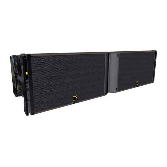
The K2 loudspeaker enclosure is based on a 3-way active design. It comprises 4 input sections: 2 LF and 1 MF at a nominal impedance of 8 ohms, and 1 HF at a nominal impedance of 16 ohms. It features two 12" speakers and four 6.5", all direct-radiating neodymium speakers mounted in a bass-reex enclosure, and two 3"... - Page 9 This symbol noties the user about instructions that must be strictly followed to ensure proper installation or operation of the product. This symbol noties the user about complementary information or optional instructions. K2 owner's manual (EN) version 1.1...
-
Page 10: System Components
Refer to the LA4X / LA8 / LA12X user manual for detailed instructions about the whole cabling scheme, including modulation cables and network. Rigging elements K2-BUMP Structure for ying K2 arrays (incl. 1 extension sling + 1 laser adapter) K2-BAR Extension bar for K2-BUMP K1-DELTA... -
Page 11: Loudspeaker Cables
Lifting chain (DIN EN 818-4) 2-leg , 8 mm K2-RIGBAR K2 rigging bar and pullback (Inc. LA-SLING2T) K2-LASERMOUNT K2 laser support plate (compatible TEQSAS / SSE Prosight / Align Array / KSG) KARADOWNK2 Flying bumper for rigging Kara under K2 Transportation accessories... -
Page 12: Rigging Elements
System components Rigging elements K2-BUMP K2-BAR K2-RAKMOUNT K2-LINK K1-DELTA K2-JACK K2-CHARIOT K-BUMPFLIGHT K2-RIGBAR K2-LASERMOUNT KARADOWNK2 K1-BPCHAIN LA-SLING2T K2-CHARIOTCOV K2 owner's manual (EN) version 1.1... -
Page 13: Electro-Acoustical Description
The K2 enclosure features an adjustable horizontal directivity system. Using the adjustable ns, horizontal directivity can be adjusted with four different settings: 110°/70° symmetric or 90° asymmetric (35°/55° or 55°/35°). A specic K2 preset must be used for each directivity setting. -
Page 14: K2 Directivity
-140 -160 -180 1 000 10 000 Frequency (Hz) Dispersion angle diagram of a K2 array with 70° ns setting, using lines of equal sound pressure at -3 dB, -6 dB, -12 dB. -100 -120 -140 -160 -180 1 000... -
Page 15: K1-Sb Applications
There are two distinct applications for K1-SB in a K2 system: • As an LF extension in a line source for enhanced throw, using the [K1SB_X K2] preset with K2. • As a subwoofer for increased impact, using the [K1SB_60] preset. -
Page 16: Preset Description
Electro-acoustical description Preset description [K2 70] [K2 90] [K2 110] loudspeaker elements outputs channels routing gain delay polarity mute left LF OUT 1 IN A 0 dB 0 ms right LF OUT 2 OUT 3 OUT 4 [KARADOWNK2] loudspeaker elements... -
Page 17: Connectors
Electro-acoustical description Connectors SpeakON connectors can be used interchangeably as IN or LINK connector. LINK 2 × 8-point PA-COM Internal pinout for L-Acoustics 3-way active enclosures PA-COM points Transducer connectors left LF right LF Kara 2 × 4-point speakON Internal pinout for L-Acoustics 2-way active enclosures... - Page 18 M adeinFrance instructionsbeforeuse EuropeanC om m unity KS28 1 × 4-point speakON K1-SB 1 × 4-point speakON Internal pinout for L-Acoustics subwoofers speakON points Transducer connectors LF + LF - Not linked Not linked K2 owner's manual (EN) version 1.1...
-
Page 19: Rigging System Description
Rigging system description Elements for enclosure rigging On both sides, K2 integrates two arms to connect another element of the rigging system, such as an enclosure or to a ying frame. • At the front, a rotating arm provides a xed point around which the enclosure can freely rotate until its connection at the rear. -
Page 20: Elements For Storage And Transportation
Elements for storage and transportation K2-CHARIOT K2-CHARIOT is designed for the transportation and storage of blocks of four K2 enclosures. During transportation the blocks must have an inter-enclosure angle of 10° to avoid any separation of the enclosures. This angle must be set using the enclosure rear rigging arm pin. The automatic locking system must remain unloaded. -
Page 21: Elements For Ground Stacking
Rigging system description Elements for ground stacking K2-CHARIOT with K2-JACK The K2-CHARIOT, combined with two K2-JACK stabilizers, is used as a stacking platform for K2 enclosures. Tipping hazard Always install the K2-JACK before: setting the inter-enclosure angles changing the position of the K2-CHARIOTrear rigging arms... -
Page 22: Elements For Ying
Elements for ying K2-BUMP K2-BUMP is designed for ying line arrays of K2, K1 or K1-SB. 4 holes are available on the central bar of the K2-BUMP. Refer to your Soundvision model to know which holes to use. With K1-SB and a single motor the hole n 2 provides a 0 site angle. - Page 23 By adding a K2-BAR to the K2-BUMP, the site angle range can be increased. 21 holes are available on the K2-BAR which can be attached to the K2-BUMP as a rear or a front extension and in position A or B, thus offering a total of 84 discrete positions for pick-up points.
- Page 24 The K2-LINK is designed as an interface between the K1 and K2 rigging systems. It is used to hang K2 under K1, K1-SB or K1-BUMP. It provides three holes and therefore three angles between the top K2 enclosure and the bottom K1 element: 0.25°, 2.5° and 5°.
- Page 25 The K2-RIGBAR can be used to implement a pullback either with K2-BUMP / K2-BAR or another K2-RIGBAR. It must be used with the LA-SLING2T. The K2-RIGBAR can also be used as the main lifting point, thus providing a lighter solution for ying K2 enclosures with one lifting point.
-
Page 26: Elements For La-Rak/La-Rak Ii Rigging
Elements for LA-RAK/LA-RAK II rigging K2-RAKMOUNT The K2-RAKMOUNT is designed to stack one or two LA-RAK/LA-RAK II on top of a own array. It is composed of four rails and a stabilizer. The rails are screwed on the K2-BUMP. Their number and position depend on the number of racks. The K2-RAKMOUNT must be used along with either one or two K2-BAR. - Page 27 Rigging system description 1 LA-RAK/LA-RAK II : 2 rails : 2 K2-BAR 2 LA-RAK/LA-RAK II : 4 rails : 1 K2-BAR When two racks are mounted side by side, the stabilizer is used to prevent the assembly from tipping or toppling over.
-
Page 28: Mechanical Safety
Always refer to Soundvision for the safety factor of a mixed array. When ying a K2 array with a Kara downll, the mechanical safety of all system elements must be considered. The indicated maximum limit applies to the K2 only. - Page 29 For other congurations, respect the recommended maximum limit for optimal stability. conguration rigging accessory safe limit maximum limit ground-stacked K2-BUMP stacked K2-CHARIOT with K2-JACK KS28 Conguration Rigging accessory Maximum limit ground-stacked no rigging accessory stacked upright no rigging accessory stacked on chariot KS28-CHARIOT K2 owner's manual (EN) version 1.1...
- Page 30 Soundvision calculations are based on usual environmental conditions. A higher safety factor is recommended with factors such as extreme high or low temperatures, strong wind, prolonged exposition to salt water, etc. Always consult a rigging specialist to adopt safety practices adapted to such a situation. K2 owner's manual (EN) version 1.1...
-
Page 31: Loudspeaker ConGurations
By providing the K1-SB with the same frequency response as the K2 low section, the [K1SB_X K2] preset allows the K1-SB enclosure to be used as an LF line source element, increasing the length of the sub-low line source. - Page 32 Recommended ratio 3 K2 : 1 K1-SB Minimum line length 12 K2 + 4 K1-SB When using [K2 70], [K2 90], or [K2 110] with [K1SB_X K2], do not add any delay value between the K2 and K1-SB elements of a same line source.
-
Page 33: Additional Subwoofer System
Loudspeaker congurations Additional subwoofer system A K2 line source or a K2/K1-SB line source can be deployed with additional subwoofer enclosures to provide increased sub-low resources to demanding applications. Two subwoofer systems are available: • K1-SB for increased LF contour •... -
Page 34: K1-Sb
Three deployments are available in this conguration: • K1-SB on top of the K2 line source • K1-SB beside the K2 or K2/K1-SB line source : side LF rejection (polarized) • K1-SB behind the K2 or K2/K1-SB line source : rear LF rejection (cardioid) - Page 35 Do not forget to add the pre-alignment and geometric delays depending on the conguration. When using [K2 70], [K2 90], or [K2 110] with [K1SB_X K2], do not add any delay value between the K2 and K1-SB elements of a same line source.
- Page 36 Do not forget to add the pre-alignment and geometric delays depending on the conguration. When using [K2 70], [K2 90], or [K2 110] with [K1SB_X K2], do not add any delay value between the K2 and K1-SB elements of a same line source.
-
Page 37: Ks28
Do not forget to add the pre-alignment and geometric delays depending on the conguration. When using [K2 70], [K2 90], or [K2 110] with [K1SB_X K2], do not add any delay value between the K2 and K1-SB elements of a same line source. - Page 38 KS28 = 0 ms K2 + K1-SB + KS28 presets pre-alignment delay values and polarity settings [K2] + [K1SB_X K2] + [KS28_60] K2 = 0 ms K1-SB = 0 ms KS28 = 0 ms [K2] + [K1SB_X K2] + [KS28_60_C] K2 = 5.5 ms...
-
Page 39: Sb28
Do not forget to add the pre-alignment and geometric delays depending on the conguration. When using [K2 70], [K2 90], or [K2 110] with [K1SB_X K2], do not add any delay value between the K2 and K1-SB elements of a same line source. - Page 40 SB28 = 0 ms K2 + K1-SB + SB28 presets pre-alignment delay values and polarity settings [K2] + [K1SB_X K2] + [SB28_60] K2 = 0 ms K1-SB = 0 ms SB28 = 0 ms [K2] + [K1SB_X K2] + [SB28_60_C] K2 = 5.5 ms...
-
Page 41: Additional DownLl Element
Do not add any delay between the K2 and Kara elements of a mixed line source. When using [K2 70], [K2 90], or [K2 110] with [K1SB_X K2], do not add any delay value between the K2 and K1-SB elements of a same line source. -
Page 42: Inspection And Preventive Maintenance
(p.43) to identify critical parts of the system and apply the specic checks described in the Inspection references (p.49). Do the Rigging check (p.54). If any parts are damaged, contact your L-Acoustics representative for further instructions. Acoustics Perform the Enclosure check (p.57). Perform the Listening test (p.59) to detect any degradation in sound quality. -
Page 43: Rigging Part Inspection
5. Check the moving parts. Make sure that the mechanism engages correctly. What to do next If a problem is detected, perform the authorized maintenance operations or contact your L-Acoustics representative. Mechanical system overview Critical parts of the lifting chains are highlighted. -
Page 44: K2 Mixed Array With K2-Bar, K2-Bump, K1-Sb, And K2-Link
Inspection and preventive maintenance K2 mixed array with K2-BAR, K2-BUMP, K1-SB, and K2-LINK Refer to Rigging part inspection (p.43). Shackles (p.52) Ball-locking pins (p.49) Ball-locking pins (p.49) Rear and front rigging arms rotate Grill safety (p.53) correctly Ball-locking pins (p.49) Ball-locking pins (p.49) -
Page 45: K2 Array With K2-Bump And Karadownk2
Inspection and preventive maintenance K2 array with K2-BUMP and KARADOWNK2 Refer to Inspection references (p.49). Shackles (p.52) Ball-locking pins (p.49) Rigging check (p.54) Grill safety (p.53) Ball-locking pins (p.49) Ball-locking pins (p.49) Ball-locking pins (p.49) Refer to the Kara owner's manual. -
Page 46: K2 Array With K2-Chariot And K2-Jack
Inspection and preventive maintenance K2 array with K2-CHARIOT and K2-JACK Refer to Inspection references (p.49). Grill safety (p.53) Ball-locking pins (p.49) Rigging check (p.54) rear rigging arms rotate correctly turn the hand wheels: the central part is raised (clockwise) or lowered... -
Page 47: K2 Array With K2-Bar, K2-Rakmount, And K2-Bump
Inspection and preventive maintenance K2 array with K2-BAR, K2-RAKMOUNT, and K2-BUMP Refer to Inspection references (p.49). Shackles (p.52) Refer to the LA-RAK II documentation for more information. Ball-locking pins (p.49) screws are tightened Ball-locking pins (p.49) Rigging check (p.54) Grill safety (p.53) -
Page 48: K2 Array With K2-Rigbar As Pullback
Inspection and preventive maintenance K2 array with K2-RIGBAR as pullback Shackles (p.52) Ball-locking pins (p.49) Rigging check (p.54) Grill safety (p.53) Ball-locking pins (p.49) Ball-locking pins (p.49) Shackles (p.52) K2 owner's manual (EN) version 1.1... -
Page 49: Inspection References
Inspection and preventive maintenance Inspection references Ball-locking pins Reference pictures tether (K2-BUMP) tether (K2-BAR) tether (K2) K2 owner's manual (EN) version 1.1... - Page 50 Inspection and preventive maintenance tether (K2) tether (K1-SB) K2 owner's manual (EN) version 1.1...
- Page 51 The pin must remain inside the hole. If the pin is inserted in two plates, the ball must pass through both plates and lock the pin in place. If the check fails, immediately withdraw the product from use and contact L-Acoustics. Related tasks Rigging part inspection (p.43)
-
Page 52: Shackles
Inspection and preventive maintenance Shackles Moving parts Drive the shackle axis in its lodging. Make sure that the end is ush with the shackle. Related tasks Rigging part inspection (p.43) K2 owner's manual (EN) version 1.1... -
Page 53: Grill Safety
Make sure that the screw is tightened. Pull on the O-rings: • Make sure they do not break. • Make sure they are not loose. GRILL (p.133) to replace them. If the O-rings are damaged or missing, refer to the K2 owner's manual (EN) version 1.1... -
Page 54: Rigging Check
Inspection and preventive maintenance Rigging check Procedure 1. Position one K2 on the rst one. 2. Secure the front rigging arms at the LINK holes. • The front rigging arms can be deployed with some resistance, and rotate correctly. • The ball-type plunger protrudes out the rigging system. - Page 55 4. Secure the rear rigging arms at one of the inter-enclosure holes. 5. Press the button to activate the automatic locking system. • The latch slightly retracts when the button is pushed (yellow label visible). K2 owner's manual (EN) version 1.1...
- Page 56 • The automatic locking system button locks and the latches engage (no yellow label visible). SHLAK! 7. Disassemble the two enclosures. Risk of trapping ngers When disassembling the enclosures, hold the top one by the handles. 8. Repeat the procedure with the other enclosures. K2 owner's manual (EN) version 1.1...
-
Page 57: Acoustical Check
6. Press the OK key or the encoder wheel to launch the ENCLOSURE CHECK. The amplied controller generates short sinusoidal signals simultaneously for each connected output. The amplied controller displays the results for each output. K2 owner's manual (EN) version 1.1... - Page 58 • a percentage of variation from the expected range (found in NOK and UNDEF results) • the number of operational transducers out of the total Low variations from the expected range are acceptable: displayed percentage can be different from 0 and all transducers considered operational. K2 owner's manual (EN) version 1.1...
-
Page 59: Listening Test
• There are foreign particles on the air gap. • The diaphragm is not centered correctly. • The screws used for reassembly are too loose. • The diaphragm is damaged. Procedure 1. Perform the diaphragm disassembly procedure. K2 owner's manual (EN) version 1.1... - Page 60 3. Clean the air gap thoroughly. Use double-face adhesive tape to remove any particles. 4. Perform the diaphragm reassembly procedure. Apply the recommended torque. 5. Repeat the listening test. If the problem persists, replace the driver. K2 owner's manual (EN) version 1.1...
-
Page 61: Rigging Procedures
After the setup, always verify no yellow labels are visible on the front and on both sides of the array. Procedure References 1. Place a block of four K2 enclosures at the nal position. A - Preparing a block of 4 K2 (p.69). - Page 62 2. Position and attach a K2-BUMP on the K1-SB stack. L - Attaching K1 or K1-SB under K2-BUMP (p.113) 3. Position and attach an upside down K2 on the K2-BUMP and add as C - Attaching K2-JACK stabilizers to K2- many K2 enclosures on top of the rst one.
-
Page 63: Flying
After the setup, always verify no yellow labels are visible on the front and on both sides of the array. At least one motor for each K2-BAR When using two K2-BAR, do not implement a bridle between the bars. Nobody behind the array when lifting enclosures To avoid collisions caused by the swinging motion, do not stand behind the array when lifting the enclosures. - Page 64 Refer to Soundvision for the number and position of the shackles. 7. Lift the assembly so you can position a block of four K2 under it. 8. Attach the block of four K2 to the K2-BUMP. H - Attaching a block of four K2 under K2- BUMP (p.92)
- Page 65 I - Attaching a block of four K2 under K2- RIGBAR (p.97) 4. Lift the array so you can position another block of four K2 under it. Verify that no yellow label is visible on both sides of the array. K2 owner's manual (EN) version 1.1...
- Page 66 Rigging procedures Procedure References 5. Position and attach a block of four K2 enclosures under the array. J - Attaching a block of four K2 under K2 (p.100) Verify that the rigging arms at the back are secured by pins and that no yellow label is visible on the front.
- Page 67 After the setup, always verify no yellow labels are visible on the front and on both sides of the array. When using two K2-BAR, do not implement a bridle between the bars. Always use at least two motors. Before setup, choose a ying option...
- Page 68 Procedure References 1. Lift the K1-SB array so you can position a block of four K2 under it. 2. Using two K2-LINK interfaces, attach the block of K2 under the K1-SB K - Attaching a block of four K2 under a K1 array.
-
Page 69: Subset Procedures
A - Preparing a block of 4 K2 min number of operators Procedure 1. Attach K2 on K2-CHARIOT. Fully rotate the rear rigging arms of K2-CHARIOT and attach a rst K2. 2. Position K2 on the K2-CHARIOT dolly. K2 owner's manual (EN) version 1.1... - Page 70 3. Secure the enclosure at the front using the LINK hole. 4. Lift the rear of the enclosure and rotate the dolly rear rigging arm in its upward position. 5. Secure the enclosure using the LINK hole. K2 owner's manual (EN) version 1.1...
- Page 71 Rigging procedures 6. Position another K2 on the rst one. Keep holding the enclosure with the handles until the front rigging arm is secured. 7. While holding the handle, rotate the front rigging arm and secure it with both LINK pins.
- Page 72 9. Make sure the automatic locking system button is unloaded. If the button has been pressed, pull to disengage the latch. 10. Repeat steps (p.69) to (p.71) until the block of four is complete. K2 owner's manual (EN) version 1.1...
-
Page 73: B - Preset The Inter-Enclosure Angles
B - Preset the inter-enclosure angles Procedure 1. On both sides, remove the pin from its current angle hole. 2. Position the pin at the chosen angle hole and slide the rigging arm until the pin goes in. K2 owner's manual (EN) version 1.1... - Page 74 Rigging procedures 3. Press the lock button to lock the inter-enclosure angle. K2 owner's manual (EN) version 1.1...
-
Page 75: C - Attaching K2-Jack Stabilizers To K2-Chariot
K2-JACK stabilizers storage position on K2-CHARIOT K2-JACK stabilizers can be attached to K2-CHARIOT during storage. The K2-JACK stabilizers must not overlap on the wheel stops. They would prevent efcient stacking of K2-CHARIOT in storage. K2 owner's manual (EN) version 1.1... - Page 76 Rigging procedures Procedure 1. Remove the two K2-JACK from the K2-CHARIOT: a) Remove the stabilizers from each bar. b) Remove the bar from the K2-CHARIOT. K2 owner's manual (EN) version 1.1...
- Page 77 Raise and turn the K2-JACK handles to secure the locking system. Dust During the K2-JACK stabilizers rst use dust will come off the threaded rod. It is expected and does not indicate a malfunction. 3. Prepare the K2-JACK stabilizers.
- Page 78 Insert the feet in the guides Pivot the feet so they come at both ends of the bar. in contact with the bar. Lock the feet in position by giving a quarter-turn to the locking system. K2 owner's manual (EN) version 1.1...
- Page 79 Rigging procedures 5. Rotate the feet clockwise to raise the K2-CHARIOT off the ground. Stop raising the stack as soon as the wheels get off the ground. K2 owner's manual (EN) version 1.1...
-
Page 80: D - Changing The Position Of The K2-Chariot Rear Rigging Arm
Rigging procedures D - Changing the position of the K2-CHARIOT rear rigging arm min number of operators Procedure Tipping hazard When the rear rigging arms are unpinned, hold the enclosures on both sides. 1. On both sides, remove the rear rigging arm pin. - Page 81 Rigging procedures 3. Use your foot to move up or move down the rear rigging arms. 4. Guide the enclosures back on the arms. K2 owner's manual (EN) version 1.1...
- Page 82 Rigging procedures 5. Pin the arms. K2 owner's manual (EN) version 1.1...
-
Page 83: E - Adjusting The K2-Chariot Site Angle
Rigging procedures E - Adjusting the K2-CHARIOT site angle Procedure 1. Verify the wheels are as close as possible to the ground without touching it. 2. Loosen one stabilizer bolt and tighten the other one depending of the target site angle. - Page 84 With the front screw jacks With the back screw jacks for a positive site angle. for a negative site angle. 4. Tighten the front or back bolts depending on the site angle. Tighten the bolt by hand only. K2 owner's manual (EN) version 1.1...
-
Page 85: F - Stacking K2 On K2-Bump
Take out and lock the rear and front rigging arms. b) Dene the K2 stack site angle with the rear rigging arm. For the top enclosure of the stack, select a value between 0.25 and 7.5 and subtract 3 to obtain the nal site angle. - Page 86 4. Remove the lower rear and front pins. 5. Turn the enclosure upside down on the K2-BUMP: a) Attach the K2 enclosure upside down on the K2-BUMP. The rigging arms should rest on the K2-BUMP spacers. b) Secure the rear arm to the K2-BUMP.
- Page 87 Rigging procedures c) Slide the front arm up and down to align the holes and secure it. Attach the front arm to the K2-BUMP. d) Raise the top enclosure to align the holes. Secure the front rigging arm. Push the locking system button to arm the latch.
- Page 88 Secure the rear arm to the lower K2 enclosure. b) Slide the front rigging arm up and down to align the holes. Attach the front arm to the lower K2 enclosure. c) Raise the top enclosure to align the holes. Secure the front rigging arm. Push the locking system button to arm the latch.
-
Page 89: G - Attaching K2-Bar To K2-Bump
Rigging procedures G - Attaching K2-BAR to K2-BUMP Procedure 1. Refer to your Soundvision model to identify the extension and position of the bar. K2 owner's manual (EN) version 1.1... - Page 90 Rigging procedures 2. Remove the pins and lift the K2-BAR using the motor. K2 owner's manual (EN) version 1.1...
- Page 91 Rigging procedures 3. Turn the K2BUMPFLIGHT 90°, lower K2-BAR and pin it according to the chosen ying option (position A or B, in front or rear extension). K2 owner's manual (EN) version 1.1...
-
Page 92: H - Attaching A Block Of Four K2 Under K2-Bump
Rigging procedures H - Attaching a block of four K2 under K2-BUMP min number of operators Procedure 1. Lower the K2-BUMP to allow for front connection. Preset inter-enclosure angles Preset the inter-enclosure angles before performing this procedure. Refer to B - Preset the inter-enclosure angles (p.73). - Page 93 2. Attach the front rigging arm on both sides: a) Rotate the arm and secure it with the K2-BUMP pin. b) Lower the K2-BUMP and secure the connection with the K2 pin. If you cannot insert the pin, move the frame back and forth.
- Page 94 Rigging procedures 3. Lower the rear of the K2-BUMP. Do not lower until contact. Leave a gap allowing to slide the K2 arm to its 5° position. 4. Attach the rear rigging arm to the frame: a) Slide the arm to its 5° position.
- Page 95 Rigging procedures 5. Raise the array to lock the inter-enclosure angles. 6. Remove K2-CHARIOT: a) Hold the dolly with one hand. Remove the back pin on both sides. K2 owner's manual (EN) version 1.1...
- Page 96 Rigging procedures b) Hold the dolly with one hand. Remove the front pin on both sides. K2 owner's manual (EN) version 1.1...
-
Page 97: I - Attaching A Block Of Four K2 Under K2-Rigbar
Rigging procedures I - Attaching a block of four K2 under K2-RIGBAR Procedure Preset inter-enclosure angles Preset the inter-enclosure angles before performing this procedure. Refer to B - Preset the inter-enclosure angles (p.73). 1. Hang the LA-SLING2T to the motor hook. - Page 98 Rigging procedures 3. Position and attach the K2 enclosures under K2-RIGBAR. Use the rear rigging middle hole. 4. Raise the array to lock the inter-enclosure angles. Do not stand behind the array The array swings backwards when it is raised.
- Page 99 Rigging procedures 5. Remove the K2-CHARIOT: a) Hold the dolly with one hand. Remove the back pin on both sides. b) Hold the dolly with one hand. Remove the front pin on both sides. K2 owner's manual (EN) version 1.1...
-
Page 100: J - Attaching A Block Of Four K2 Under K2
Preset the inter-enclosure angles before performing this procedure. Refer to B - Preset the inter-enclosure angles (p.73). 1. Attach the front rigging arm on both sides: a) Rotate the arm to align its hole with the K2 rigging hole. K2 owner's manual (EN) version 1.1... - Page 101 Pin the arm in the LINK hole of the own array. c) Lower the own array and secure the assembly with the LINK pin. If you cannot insert the pin, move the own array back and forth with enclosure handle. K2 owner's manual (EN) version 1.1...
- Page 102 Rigging procedures 2. Lock the inter-enclosure angles of the block. Raise the array. The lower K2 enclosures swing and the latches automatically lock. K2 owner's manual (EN) version 1.1...
- Page 103 Rigging procedures 3. Attach the lower K2 enclosures rear rigging arm to the back of the array: a) Turn the wheels inside the dolly. b) Pull back the bottom enclosures while lowering the array until the array and the top enclosure of the block are in contact.
- Page 104 Position the pin at the entrance of the chosen angle hole and slide the rigging arm until the pin goes in. e) Press the lock button. 4. Raise the array to lock the inter-enclosure angle. The latches automatically lock. K2 owner's manual (EN) version 1.1...
- Page 105 Rigging procedures 5. Remove the K2-CHARIOT: a) Hold the dolly with one hand. Remove the back pin on both sides. b) Hold the dolly with one hand. Remove the front pin on both sides. K2 owner's manual (EN) version 1.1...
-
Page 106: K - Attaching A Block Of Four K2 Under A K1 System Element
Rigging procedures K - Attaching a block of four K2 under a K1 system element Procedure K1 / K1-SB must always be on top of a K2 array. Preset inter-enclosure angles Preset the inter-enclosure angles before performing this procedure. Refer to B - Preset the inter-enclosure angles (p.73). - Page 107 Pin the arm on the own array. c) Lower the own array and secure the assembly with the LINK pin. If you cannot insert the pin, move the own array back and forth with enclosure handle. K2 owner's manual (EN) version 1.1...
- Page 108 Rigging procedures 2. Raise the array to lock the inter-enclosure angles. 3. Turn the wheels inside the dolly. K2 owner's manual (EN) version 1.1...
- Page 109 Rigging procedures 4. Connect the rear of the K1/K1-SB array to the rear of the K2 array with the K2-LINK interfaces: a) On both sides, attach a K2-LINK at the back of the K1-SB enclosure. Do not pin K2-LINK on K2.
- Page 110 Rigging procedures b) Pull back the bottom enclosures while lowering the array until only the front wheel touches the ground. c) Push the K2-LINK into the K2 rear rigging. K2 owner's manual (EN) version 1.1...
- Page 111 Rigging procedures 5. Lower the array until the hole of K2-LINK matches the K2 rigging middle hole. Risk of pinching Do not touch the K2-LINK while lowering the array. 6. Secure the K2-LINK on the K2 rigging middle hole. K2 owner's manual (EN) version 1.1...
- Page 112 7. Remove the K2-CHARIOT: a) Raise the array. b) Hold the dolly with one hand. Remove the back pin on both sides. c) Hold the dolly with one hand. Remove the front pin on both sides. K2 owner's manual (EN) version 1.1...
-
Page 113: L - Attaching K1 Or K1-Sb Under K2-Bump
1. Slide out K1-SB front rigging arm and pin it at 0° on both sides. 2. Attach the K2-BUMP to the K1 elements block: a) Remove the K2-BUMP rear and front pins on both sides. Lower the K2-BUMP so it rests on the topmost enclosure. - Page 114 Rigging procedures b) Rotate the rear rigging arm and pin it on the frame. c) Pin the front rigging arm on the frame. K2 owner's manual (EN) version 1.1...
-
Page 115: M - Mounting La-Rak/La-Rak Ii On K2-Bump
6 mm hex bit 13 mm wrench Procedure 1. Remove the nuts and bolts from the K2-RAKMOUNT rails. 2. Position and secure as many rails as necessary on the K2-BUMP. 1 LA-RAK/LA-RAK II 2 LA-RAK/LA-RAK II K2 owner's manual (EN) version 1.1... - Page 116 Before securing the side rails, make sure the frame pins are on the outside. 4. Install as many K2-BAR as necessary. When installing a single K2-BAR at the center of the frame, make sure the pins are inserted between the central bar of the frame and the closest rail.
- Page 117 Always insert so the metallic safety is pointed upward (depending on the tilt angle). c) Secure the LA-RAK/LA-RAK II with the coupling bars. Insert the spring-loaded safety in the LA-RAK/LA-RAK II rails, give a quarter turn and slide the bar until the safety locks into place. K2 owner's manual (EN) version 1.1...
- Page 118 6. If you are stacking 2 LA-RAK/LA-RAK II side-by-side on K2-BUMP, then insert the stabilizer between the two racks: a) Release the locking system by raising and turning the handle. Insert the stabilizer on the side opposite to the K2- BAR: •...
- Page 119 Rigging procedures b) Secure the stabilizer by locking the handle. K2 owner's manual (EN) version 1.1...
-
Page 120: N - Using A K2-Rigbar To Implement A Pullback
Rigging procedures N - Using a K2-RIGBAR to implement a pullback Space between linking points The space between the two linking points used for this conguration must be aligned with the array pickup points. The deployment load-bearing lines must be parallel to each other. - Page 121 The additional safety must either be: A two-leg bridle sling with a pickup Two safety slings. point higher than the LA-SLING2T. Do not use the rear rigging middle hole. 3. Attach the K2-RIGBAR to the bottom enclosure. K2 owner's manual (EN) version 1.1...
- Page 122 Use the rear rigging bottom hole. 4. Adjust the height of the pickup-point. Do not raise the rear pick-up point above the front pick-up point. The chains must be as vertical as possible. Under K2-RIGBAR Under K2-BAR K2 owner's manual (EN) version 1.1...
-
Page 123: O - Rigging A Kara DownLl Array Under A K2 Array
• Prepare an array of three Kara with 0° inter-enclosure angles. • Position the Kara array under the K2 array. Make sure the latches on the bottom K2 are in storage position. Procedure 1. Take out the four rigging arms on the top Kara enclosure: a) Lock the front rigging arms in linking position. - Page 124 Position the higher ledge at the rear. Secure the Kara rigging arms inside the slits with the ball-locking pins. 3. Lower the K2 array as close as possible to the assembly without resting on it. K2 owner's manual (EN) version 1.1...
- Page 125 Disconnect any cable from the K2 bottom connector. 5. Connect KARADOWNK2 to the bottom of the K2 array: a) Rotate the top Kara upwards and secure the rear KARADOWNK2 tabs to the K2 rigging. K2 owner's manual (EN) version 1.1...
- Page 126 Slightly lower the K2 array if necessary. c) Reconnect the top Kara at the rear to the assembly. 6. Raise the array. Do not implement a pullback on a K2 array with a Kara downll. 7. Set the inter-enclosure angles. Refer to the Kara owner's manual.
-
Page 127: Connection To La AmpliEd Controllers
Refer to the cabling schemes to connect the enclosures to different types of output connectors. L-Acoustics does not supply the speakON-to-PA-COM interface. It must be built with two 4-point speakON connectors and a female 8-point PA-COM connector (no cable clamp). - Page 128 Four-channel CA-COM output 2WAY 2W CH(A) SUB1 SUB2 2W CH(B) Two-channel speakON output 1+/1- 2+/2- Cabling schemes for subwoofers Two-channel speakON output CH(1) SP-Y1 CC4FP CH(2) 1+/1- 2+/2- Four-channel CA-COM output SPK1 SPK2 SPK3 SPK4 K2 owner's manual (EN) version 1.1...
-
Page 129: Corrective Maintenance
Refer to the Kara owner's manual and the KS28 user manual for more information on the corrective maintenance. Disassembly and Reassembly procedures In order to operate, follow the order outlined here. MF SPEAKER KR HPFA61 VARIABLE DIRECTIVITY FINS GRILL LF SPEAKER KR HPBC125 K2 owner's manual (EN) version 1.1... - Page 130 • blue threadlocker Repair kit KR HPBC34 Kit HP BC34 Driver 3 - 8 ohms ×8 S100035 M5×16 Torx Disassembly Procedure 1. Remove the eight screws securing the connector plate. Save the screws for reassembly. K2 owner's manual (EN) version 1.1...
- Page 131 Corrective maintenance 2. Remove the connector plate using a lever. Avoid straining the speaker cables. 3. Disconnect the cables. K2 owner's manual (EN) version 1.1...
- Page 132 1. Connect the cables. 2. Position the connector plate using the label as a reference. Gradually tighten the screws following a star pattern. Put blue threadlocker on the screws. 3. Secure the connector plate. 3 N.m K2 owner's manual (EN) version 1.1...
- Page 133 If the grill is secured with an O-ring, pull it down before removing the grill. 1. Loosen the captive screw of the grill mounting bracket. 4 mm 2. Slide down the grill and remove it. K2 owner's manual (EN) version 1.1...
- Page 134 Use a at-head screwdriver to push the O-ring under the insert. 2. Apply blue threadlocker on the grill screw. 3. Insert the top of the grill. Stretch the O-ring with the tool provided in the KR. K2 owner's manual (EN) version 1.1...
- Page 135 Corrective maintenance 4. Close the grill. Pull the O-ring so it goes around the grill logo and above the captive screw. 5. Secure the grill with the captive screw. 3 N.m 4 mm K2 owner's manual (EN) version 1.1...
- Page 136 Kit HP FA61 Driver 6.5'' - 8 ohms ×4 ×4 ×1 S100108 S321 1396 M5×45 hex washer with gasket dust cover gasket Prerequisite Grill removed. GRILL (p.133). Disassembly Procedure 1. Unhook the n with a at tool. K2 owner's manual (EN) version 1.1...
- Page 137 For safety reasons, always use the new screws and spare parts provided in the KR. If no new screws are available, use blue threadlocker. Procedure 1. Secure the n with the provided screws and washers. 3 N.m 4 mm K2 owner's manual (EN) version 1.1...
- Page 138 Corrective maintenance 2. Clip the moving part in the frame. 3. Verify the n mobility. K2 owner's manual (EN) version 1.1...
- Page 139 For safety reasons, always use the new screws and spare parts provided in the KR. If the speaker gasket is damaged, remove and replace it. 5 N.m 5 mm What to do next Perform the Acoustical check (p.57) procedures. K2 owner's manual (EN) version 1.1...
- Page 140 Gradually tighten the screws following a star pattern. If the speaker gasket is damaged, remove and replace it. 3 N.m 4 mm Position the connectors toward the ns. What to do next Perform the Acoustical check (p.57) procedures. K2 owner's manual (EN) version 1.1...
- Page 141 CONNECTOR PLATE (p.130). Disassembly Procedure 1. Remove the HF driver cables. Free the cables by pressing the driver push-buttons. 2. Remove the two screws securing the assembly. Save the screws for reassembly. 5 mm K2 owner's manual (EN) version 1.1...
- Page 142 Corrective maintenance 3. Remove the HF driver assembly. K2 owner's manual (EN) version 1.1...
- Page 143 1. Position the HF driver assembly in the cabinet. Align the plate with the cabinet inserts and position the red connector on the left. 2. Secure the assembly. 5 N.m 5 mm 3. Connect the corresponding speaker cables to the high-frequency driver. K2 owner's manual (EN) version 1.1...
- Page 144 M4×14 hex Prerequisite Connector plate removed. CONNECTOR PLATE (p.130). HF driver removed. HF DRIVER (p.141). The HF driver assembly is placed on a at surface in a dust-free environment. Exploded view 3.5 N.m 3 mm K2 owner's manual (EN) version 1.1...
- Page 145 Tighten the screws in the same order with the torque screwdriver. Use the 3 mm hex bit and set the torque to 3.5 Nm. What to do next Perform the Acoustical check (p.57) procedures. K2 owner's manual (EN) version 1.1...
- Page 146 Corrective maintenance TEMPORARY MEASURE FOR K2 REAR AND FRONT RIGGING PINS Repair kit KR PIN1394 Kit 2 x pin 1394 ×2 1394 ball-locking pin Ø3/8" with lanyard KR PIN163 Kit K1 6 ball head pins ×6 ball-locking pin Ø1/2"with lanyard Contact your Certied Provider to nalize the ball-locking pins installation.
- Page 147 Corrective maintenance K2 owner's manual (EN) version 1.1...
-
Page 148: K1-Sb
Corrective maintenance K1-SB Disassembly and Reassembly procedures In order to operate, follow the order outlined here. LF SPEAKER KR HPPH154 GRILL RIGGING PINS KR PIN163 SIDE RIGGING K2 owner's manual (EN) version 1.1... - Page 149 The enclosure is placed on its top. Exploded view For safety reasons, always use the new screws and spare parts provided in the KR. If no new screws are available, use blue threadlocker. 3 N.m 4 mm K2 owner's manual (EN) version 1.1...
- Page 150 * The screws and fasteners are also provided in the KR HPPH154 (Kit HP PH154 Speaker 15'' - 8 ohms ). Prerequisite Grill disassembled. GRILL (p.149). Exploded view For safety reasons, always use the new screws and spare parts provided in the KR. 5 N.m 5 mm K2 owner's manual (EN) version 1.1...
- Page 151 Corrective maintenance D/R - SIDE RIGGING PROTECTION Tools • torque screwdriver • T30 Torx bit Consumables • blue threadlocker Exploded view Save the screws and fasteners for reassembly. Use blue threadlocker. 3 N.m K2 owner's manual (EN) version 1.1...
- Page 152 M4.8×18 rivet plain washer Ø5 mm ×6 ball-locking pin Ø1/2"with lanyard The S142, S254, and S158 are not used in this procedure. Prerequisite Side rigging protection removed. SIDE RIGGING PROTECTION (p.151). Exploded view 3 N.m K2 owner's manual (EN) version 1.1...
-
Page 153: Sb28
Corrective maintenance SB28 Disassembly and Reassembly procedures In order to operate, follow the order outlined here. LF SPEAKER KR HPBM181 GRILL K2 owner's manual (EN) version 1.1... - Page 154 Corrective maintenance D/R - GRILL Tools • torque screwdriver • 5 mm hex bit Consumables • blue threadlocker Exploded view Save the screws and fasteners for reassembly. Use blue threadlocker. 5 N.m 5 mm K2 owner's manual (EN) version 1.1...
- Page 155 Prerequisite Grill disassembled. GRILL (p.154). Exploded view For safety reasons, always use the new screws and spare parts provided in the KR. Gradually tighten the screws following a star pattern. 5 N.m 5 mm K2 owner's manual (EN) version 1.1...
-
Page 156: K2-Bump
Corrective maintenance K2-BUMP Disassembly and Reassembly procedures In order to operate, follow the order outlined here. RIGGING PINS KR PIN163 RIGGING PINS KR PIN1394 K2 owner's manual (EN) version 1.1... - Page 157 The S254 are not used (represented for comparison) Exploded view For safety reasons, always use the new screws and spare parts provided in the KR. Position the at side of the steel tab toward the rigging element. K2 owner's manual (EN) version 1.1...
- Page 158 Ø3/8" with lanyard M4.8×18 rivet Exploded view For safety reasons, always use the new screws and spare parts provided in the KR. Position the at side of the steel tab toward the rigging element. K2 owner's manual (EN) version 1.1...
-
Page 159: K2-Bar
Corrective maintenance K2-BAR Disassembly and Reassembly procedures In order to operate, follow the order outlined here. RIGGING PINS KR PIN1542 K2 owner's manual (EN) version 1.1... - Page 160 Kit 2 x pin 1542 ×2 ×2 S142 1542 M4×10 rivet round head ball-locking pin Ø5/8" with lanyard Exploded view For safety reasons, always use the new screws and spare parts provided in the KR. K2 owner's manual (EN) version 1.1...
-
Page 161: SpeciCations
Description 3-way full-range active WST enclosure, quad-amplied by LA4X / LA8 / LA12X Usable bandwidth (-10 dB) 35 Hz - 20 kHz ([K2 70]) Maximum SPL 147 dB ([K2 70]) Nominal directivity horizontal: 110°/70° symmetric or 90° asymmetric (35°/55° or 55°/35°) - Page 162 Specications K2 dimensions 400 mm / 15.8 in 354 mm / 13.9 in 1338 mm / 52.7 in K2 owner's manual (EN) version 1.1...
- Page 163 Finish dark grey brown Pantone 426 C pure white RAL 9010 IP45 Peak level at 1 m under half space conditions using pink noise with crest factor 4 (preset specied in brackets). K2 owner's manual (EN) version 1.1...
- Page 164 Specications K1-SB dimensions 520 mm / 20.5 in 438 mm / 17.1 in 505 mm / 19.9 in 1342 mm / 52.8 in K2 owner's manual (EN) version 1.1...
- Page 165 Peak level at 1 m under half space conditions using pink noise with crest factor 4 (preset specied in brackets). KS28 dimensions 702 mm / 27.6 in 1340 mm / 52.8 in 1351 mm / 53.2 in K2 owner's manual (EN) version 1.1...
- Page 166 Rigging components high grade steel with anti-corrosion coating Finish dark grey brown Pantone 426 C Peak level at 1 m under half space conditions using pink noise with crest factor 4 (preset specied in brackets). K2 owner's manual (EN) version 1.1...
- Page 167 Specications SB28 dimensions 700 mm / 27.6 in 1300 mm / 51.2 in K2 owner's manual (EN) version 1.1...
- Page 168 Specications K2-BUMP specications Description Structure for ying K2 arrays (incl. 1 extension sling + 1 laser adapter) 2 × Ø19 mm shackles WLL 3.25 t Weight (net) 42.3 kg / 93.3 lb Material high grade steel with anti-corrosion coating K2-BUMP dimensions 1387 mm / 54.6 in...
- Page 169 Specications K-BUMPFLIGHT specications Description Modular ight case for 2 K1-BUMP or 2 K2-BUMP 12 pieces of adhesive foam Weight (net) 105 kg / 231.5 lb K-BUMPFLIGHT dimensions 1469 mm / 57.8 in 643 mm / 25.3 in K2 owner's manual (EN) version 1.1...
- Page 170 2 × Ø19 mm shackles WLL 3.25 t Weight (net) 17 kg / 37.5 lb Material high grade steel with anti-corrosion coating K2-BAR dimensions 1254 mm / 49.4 in 78 mm / 3.1 in K2 owner's manual (EN) version 1.1...
- Page 171 Specications K2-LINK specications Description Rigging accessory for rear attachment of K2 below K1 Weight (net) 1.8 kg / 4 lb Material high grade steel with anti-corrosion coating K2-LINK dimensions 10 mm / 0.4 in 201 mm / 7.9 in K2 owner's manual (EN) version 1.1...
- Page 172 2.2 kg / 4.9 lb (stabilizer) Material high grade steel with anti-corrosion coating K2-RAKMOUNT dimensions Rail 161.9 mm / 6.3 in 60 mm / 2.4 in Stabilizer 175 mm / 6.9 in 42 mm / 1.7 in K2 owner's manual (EN) version 1.1...
- Page 173 Rigging accessory for rear attachment of 2 motors to K1-BUMP Weight (net) 9.5 kg / 21 lb Material high grade steel with anti-corrosion coating K1-DELTA dimensions 606 mm / 23.8 in 48 mm / 1.9 in K2 owner's manual (EN) version 1.1...
- Page 174 Nominal length incl. hooks 3.7 kg / 1.2 lb Maximum sling angle β 60° 2.8 t for β : 0° - 45° Load rating 2 t for β : 46° - 60° LA-SLING2T illustration K2 owner's manual (EN) version 1.1...
- Page 175 Specications K1-BPCHAIN specications Description Adjustable sling for K1-BUMP or K2-BUMP Weight (net) 6.3 kg / 13.9 lb Material high grade steel with anti-corrosion coating K1-BPCHAIN dimensions 132 mm / 5.2 in 30 mm / 1.2 in 1370 mm / 53.9 in 110 mm / 4.3 in...
- Page 176 Specications K2-RIGBAR specications Description K2 rigging bar and pullback (Inc. LA-SLING2T) Weight (net) 15.5 kg / 34.2 lb Material high grade steel with anti-corrosion coating K2-RIGBAR dimensions 1334 mm / 52.5 in 1250 mm / 49.2 in 199 mm / 7.8 in 1162 mm / 45.7 in...
- Page 177 Specications K2-CHARIOT specications Description Chariot for 4 K2 Weight (net) 50 kg / 110.2 lb Material high grade steel with anti-corrosion coating K2-CHARIOT dimensions 1450 mm / 57.1 in 610 mm / 24 in K2 owner's manual (EN) version 1.1...
- Page 178 Specications K2-JACK specications Description 4 tilt adjustment screw jacks + bar for K2-CHARIOT Weight (net) 10.1 kg / 22.3 lb (for one stabilizer) Material high grade steel with anti-corrosion coating K2-JACK dimensions 1278 mm / 50.3 in 124 mm / 4.9 in...
- Page 179 Specications K2-LASERMOUNT specications Description K2 laser support plate (compatible TEQSAS / SSE Prosight / Align Array / KSG) Weight (net) 0.74 kg / 1.6 lb Material high grade steel with anti-corrosion coating K2-LASERMOUNT dimensions 205 mm / 8.1 in 41 mm / 1.6 in...
- Page 180 Specications KARADOWNK2 specications Description Flying bumper for rigging Kara under K2 Weight (net) 17 kg / 37 lb Material high grade steel with anti-corrosion coating KARADOWNK2 dimensions 68 mm / 2.7 in 1311 mm / 51.6 in 90 mm / 3.5 in 1330 mm / 52.4 in...
-
Page 181: Appendix A: Pickup Points Guidelines
Use two LA-SLING2T to implement bridle hangs. One leg of the LA-SLING2T must always be connected to the K2-BAR hole no 1 (i.e., the closest to the array). The other leg can be connected to holes no 11 to n o 21. - Page 182 Pickup points guidelines K2 owner's manual (EN) version 1.1...
- Page 183 Pickup points guidelines K2-BUMP with no LA-RAK/LA-RAK II Not OK K2 owner's manual (EN) version 1.1...
- Page 184 Pickup points guidelines K1-DELTA for azimuth control To control the azimuth of a own K2 line, attach the K1-DELTA to the rear pickup point. The recommended space between the two lifting point is 1 m / 33 ft. By adjusting the height of both pickup points you can adjust the azimuth angle from -10° to +10°.
-
Page 185: Appendix B: Installing A Laser Inclinometer
1. Remove the four M4 Torx screws (T20) from the plate. 2. Put thread-locker in the four threaded inserts. 3. Position the sensor so it points toward the front of the K2-BUMP. 4. Secure the sensor with the four screws. - Page 186 Installing a laser inclinometer SSE PROSIGHT Procedure 1. Install the SSE PROSIGHT laser in the SSE K2 BUMP bracket. 2. Remove the nuts from the top studs. 3. Position the assembly inside the K2-BUMP. K2 owner's manual (EN) version 1.1...
- Page 187 Installing a laser inclinometer 4. Secure the assembly with the two nuts. K2 owner's manual (EN) version 1.1...
- Page 188 Installing a laser inclinometer K2-LASERMOUNT ® The L-ACOUSTICS K2-LASERMOUNT is a support plate designed to attach a remote laser inclinometer to the side of ® ® a K2 enclosure. It is compatible with ve sensor models: TEQSAS LAP-TEQ PLUS (part of the L-ACOUSTICS TECH ®...
- Page 189 Installing a laser inclinometer 2. Rotate the front arm and secure it with its pin. 3. Position the K2-LASERMOUNT on the side of the enclosure. 4. Maintain the K2-LASERMOUNT in position by tightening the knob. K2 owner's manual (EN) version 1.1...
- Page 190 Installing a laser inclinometer 5. Secure the K2-LASERMOUNT by running the sling inside and around the K2 handle and locking it on itself. K2 owner's manual (EN) version 1.1...
-
Page 191: Appendix C: Recommendation For Speaker Cables
8 Ω load 4 Ω load 2.7 Ω load Use the more detailed L-Acoustics calculation tool to evaluate cable length and gauge based on the type and number of enclosures connected. The calculation tool is available on our website: https://www.l-acoustics.com/en/installation/tools/... - Page 192 L-Acoustics 13 rue Levacher Cintrat - 91460 Marcoussis - France +33 1 69 63 69 63 - info@l-acoustics.com www.l-acoustics.com...
Need help?
Do you have a question about the K2 and is the answer not in the manual?
Questions and answers