Table of Contents
Advertisement
Advertisement
Chapters
Table of Contents

Related Manuals for L-Acoustics 108P


Summary of Contents for L-Acoustics 108P
- Page 1 Version 2.1 May 2007 L-ACOUSTICS P SERIES 108P, 112P, SB15P OPERATOR MANUAL...
-
Page 2: Important Safety Instructions
15. Since the mains power supply cord attachment plug is used as disconnect device, the plug should always be easily accessible. 16. Fire ignition sources such as candles should not be placed on the product or in close proximity to the product. L-ACOUSTICS P Series Manual V2.1 7/12/2007... - Page 3 (@230V voltage selector position) Before applying AC power, ensure that the voltage selector is correctly set for the mains power source (115 V or 230 V) and that the fuse has the appropriate rating. L-ACOUSTICS P Series Manual V2.1 7/12/2007...
-
Page 4: Foreword
FOREWORD Thank you for purchasing the 108P, 112P or SB15P self-powered loudspeaker system. This manual is intended to provide you with the information you require to effectively install and operate your P series loudspeaker in a variety of professional sound reinforcement applications. -
Page 5: Table Of Contents
TABLE OF CONTENTS ..........................4 LIST OF FIGURES............................5 1. THE P SERIES ............................6 1.1 OVERVIEW.............................. 9 1.2 108P, 112P SERIES PRESETS........................12 1.3 SB15P PRESETS............................13 1.4 108P DESCRIPTION ..........................14 1.5 112P DESCRIPTION ..........................15 1.6 SB15P DESCRIPTION ..........................16 2. -
Page 6: List Of Figures
Figure 7: 108P, 112P preset selector switch closeup and preset options………………………………….. Figure 8: SB15P preset selector switch closeup…………………………………………………………….. Figure 9: SB15P with positive polarity, 108P or 112P in X-OVER mode ………………………………….. Figure 10: SB15P with negative polarity, 108P or 112P in FRONT mode …………………………………... -
Page 7: The P Series
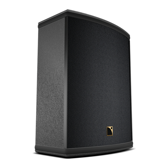
When used with the L-ACOUSTICS SB15P self-powered subwoofer, the 108P and 112P can also be used for side fill, drum monitoring or small-to-medium format front-of-house (FOH) applications. In addition to these applications, the 108P is specifically optimized for use as a high-power nearfield monitor while the 112P provides a high-performance stage monitoring solution. -
Page 8: Figure 2: Sb15P Self-Powered Subwoofer
Self-powered 15” subwoofer enclosure Figure 2: SB15P self-powered subwoofer RIGGING ACCESSORIES (4) ETR8-2 Adjustable U-Bracket for ceiling, wall or scaffold mounting of the 108P (5) ETR112XT Adjustable U-Bracket for ceiling, wall or scaffold mounting of the 112P (6) ETR15P Adjustable U-Bracket for ceiling, wall or scaffold mounting of the SB15P... -
Page 9: Figure 3: P Series Rigging Components
ETR8-2 ETR112XT XT-LIFTBAR ETR15P Figure 3: P Series Rigging Components L-ACOUSTICS P Series Manual V2.1 7/12/2007... -
Page 10: Overview
Accurate frequency response and imaging combined with elevated SPL output capacity make the 108P ideal for use as a high performance nearfield monitor for live FOH mix engineering and for stereo or 5.1 monitoring in studio, broadcast or post production environments. For nearfield... -
Page 11: Figure 5: 112P Enclosure
A/V, houses of worship, club, or television applications. When used with the L-ACOUSTICS SB15P self- powered subwoofer, the 112P is also highly suitable for side fill, drum monitoring or small-to- medium format front-of-house (FOH) applications. -
Page 12: Figure 6: Sb15P Enclosure
A built-in pole mount socket is provided as standard, facilitating the creation of a compact FOH system when the SB15P is used with 108P or 112P enclosures. An adjustable U bracket is available as an optional rigging accessory for ceiling, wall, scaffold or truss mounting, adding a unique degree of versatility for fixed installation. -
Page 13: 112P Series Presets
MONITOR presets are nominally flat under half-space measurement conditions XOVER presets apply a 100 Hz highpass filter and a 3 dB high frequency shelving equalization contour for use of the 108P or 112P with the L-ACOUSTICS SB15P self-powered subwoofer. L-ACOUSTICS P Series Manual V2.1... -
Page 14: Sb15P Presets
Figure 8: SB15P preset selector switch closeup Figure 9: SB15P with positive polarity, 108P or 112P in X-OVER mode provides a 3 dB sub/low frequency contour (rear panel volume at 0 dB) Figure 10: SB15P with negative polarity, 108P or 112P in FRONT mode provides a 6 dB sub/low frequency contour (rear panel volume at 0 dB). -
Page 15: Description
MONITOR has nominally flat response under half-space loading conditions; X-OVER provides a 100 Hz high pass filter and +3 dB high frequency shelving characteristics for use of the 108P with the L- ACOUSTICS SB15P self-powered subwoofer. Connection to the 108P is made via two parallel XLR connectors and gain is controllable via rear panel volume potentiometer. -
Page 16: Figure 12: 112P (Floor Monitor Orientation)
X-OVER provides a 100 Hz high pass filter and +3 dB high frequency shelving characteristics for use of the 112P with the L-ACOUSTICS SB15P self-powered subwoofer. Connection to the 112P is made via two parallel XLR connectors and gain is controllable via rear panel volume potentiometer. -
Page 17: Sb15P Description
108P or 112P. Positive or negative polarity operation is selectable via rear-panel push button switch. When used with 108P or 112P enclosures in X-OVER mode, the SB15P should be operated with positive polarity. When used with 108P or 112P enclosures in FILL, FRONT or MONITOR mode, the SB15P should be operated with negative polarity. -
Page 18: Figure 13: Sb15P (With Pole-Mounted 108P )
ETR15P U-bracket accessory for rigging the enclosure in either horizontal or vertical orientations with continuous angular adjustment. Figure 13: SB15P (with pole-mounted 108P ) L-ACOUSTICS P Series Manual V2.1 7/12/2007... -
Page 19: Connectors And Cables
Always use the mains power cable that was provided with your 108P, 112P or SB15P. 115V mains cable 230V mains cable Figure 15: P Series mains power cables Do not connect 108P, 112P or SB15P loudspeakers to an unearthed mains supply or by using an unearthed mains cable. L-ACOUSTICS P Series Manual V2.1 7/12/2007... -
Page 20: Figure 16: Daisy-Chain Connection Of P Series Enclosures
–ve Unbalanced sources (for example, RCA or ¼” TS phone jack connectors) can be connected to the 108P or 112P provided that pin 3 is grounded to pin 1 (see Figure 17). Figure 17: Connecting unbalanced sources L-ACOUSTICS P Series Manual V2.1... -
Page 21: Applications
Note: When cabling your P Series loudspeaker for the first time, set the volume control fully counter- clockwise (-∞). The input sensitivity of the 108P, 112P or SB15P can be matched to the output of the mixing console (or other program source) by using the volume control on the rear panel. -
Page 22: Distributed Sound Reinforcement
(100 degrees for 108P, 90 degrees for 112P) and the throw distance to the audience listening plane. In general, the goal is to separate P Series enclosures so that the -6 dB coverage angle of one enclosure is aligned with the main 0 degree axis of the other enclosure (and vice versa) at the listening plane of the audience. -
Page 23: Nearfield Monitoring
For nearfield monitoring, either FILL (free space conditions, for example, when the 108P is placed on a console bridge) or MONITOR (half space conditions, for example, when the 108P is wall- or soffit- mounted) presets should be selected. -
Page 24: Installation Procedures
4. INSTALLATION PROCEDURES The ETR8-2 is an optional accessory U-Bracket for wall or ceiling mounting of the 108P. Note: Always orient the ETR8-2 with the fixed arm on the bottom when installing the 108P in the vertical orientation 4.1 ETR8-2 U-BRACKET ATTACHMENT... -
Page 25: Etr112Xt U-Bracket Attachment
(7) Rotate the pivoting arm into position – the pivoting arm locking pin (8) Rotate the loudspeaker into position and select the desired angle. automatically secures the U-bracket Secure using the locking pins on both fixed and pivoting arms L-ACOUSTICS P Series Manual V2.1 7/12/2007... -
Page 26: Xtliftbar Attachment
(front to back) provide +18, +11, +3, -5, -13 degree tilt the center of gravity. angles, respectively Figure 22: XTLIFTBAR installation procedure L-ACOUSTICS P Series Manual V2.1 7/12/2007... -
Page 27: Etr15P U-Bracket Attachment
(8) The recessed M8 insert (8 mm diameter) is available for attachment adjustment knob (pivoting arm locking pin automatically secures the U- of an I-Bolt plus safety steel bracket as the adjustment knob is tightened) Figure 23: ETR15P U-bracket installation procedure L-ACOUSTICS P Series Manual V2.1 7/12/2007... -
Page 28: Safety Rules
21435 or equivalent). The footprint (base diameter) must be at least 1300 mm and withstand a maximum centric load of 350 N (35 kg) or higher. Tripod stand legs must be completely opened and the height must not exceed 2020 mm when used with the 108P and 1420 mm when used with the 112P. -
Page 29: P Series Loudspeaker Operation
Ensure that the program signal source (mixing console output) is muted before powering your P series loudspeaker. Power up the 108P, 112P or SB15P by connecting the PowerCon cable that was provided with your P series loudspeaker to an appropriate mains power source. -
Page 30: Specifications
2 x XLR, 2 x PowerCon (input, loop through) Material 15 mm, 18 mm Baltic birch plywood Finish Maroon-gray™ Grill Black epoxy perforated steel with acoustically-transparent, technically- advanced grille cloth Rigging Integrated pole mount socket, adjustable U-bracket accessory available L-ACOUSTICS P Series Manual V2.1 7/12/2007... -
Page 31: Figure 24: 108P Line Drawing
Figure 24: 108P Line Drawing L-ACOUSTICS P Series Manual V2.1 7/12/2007... -
Page 32: Figure 25: 108P + Etr8-2 Line Drawing
Figure 25: 108P + ETR8-2 Line Drawing L-ACOUSTICS P Series Manual V2.1 7/12/2007... -
Page 33: Specifications
2 x XLR, 2 x Power Con (input, loop through) Material 18 mm, 30 mm Baltic birch plywood Finish Maroon-gray™ Grill Black epoxy perforated steel with acoustically-transparent, technically- advanced grille cloth Rigging Integrated pole mount socket, adjustable U-bracket and liftbar accessories available L-ACOUSTICS P Series Manual V2.1 7/12/2007... -
Page 34: Figure 26: 112P Line Drawing
Figure 26: 112P Line Drawing L-ACOUSTICS P Series Manual V2.1 7/12/2007... -
Page 35: Figure 27: 112P + Etr112Xt Line Drawing
Figure 27: 112P + ETR112XT Line Drawing L-ACOUSTICS P Series Manual V2.1 7/12/2007... -
Page 36: Figure 28: 112P + Xtliftbar Line Drawing
Figure 28: 112P + XTLIFTBAR Line Drawing L-ACOUSTICS P Series Manual V2.1 7/12/2007... -
Page 37: Sb15P Specifications
18 mm, 24 mm Baltic birch plywood Finish Maroon-gray™ Grill Black epoxy perforated steel with acoustically-transparent, technically- advanced grille cloth Rigging Integrated pole mount socket, adjustable U-bracket accessory available Safety Insert for attachment of an I-Bolt L-ACOUSTICS P Series Manual V2.1 7/12/2007... -
Page 38: Figure 29: Sb15P Line Drawing
Figure 29: SB15P Line Drawing L-ACOUSTICS P Series Manual V2.1 7/12/2007... -
Page 39: Figure 30: Sb15P + Etr15P Line Drawing
Figure 30: SB15P + ETR15P Line Drawing L-ACOUSTICS P Series Manual V2.1 7/12/2007... -
Page 40: Warranty And Disclaimers
3 years from the date of original purchase. During the warranty period, L-ACOUSTICS or its nominated agents will undertake to repair, or at its option, replace this product at no charge to its owner if it fails to perform as specified, provided that the unit is returned undamaged and shipped pre-paid to the factory or an authorised service facility. - Page 41 France Country of origin for components of the product: EEC Standards conformity L-ACOUSTICS hereby declares that the 108P loudspeaker conforms to : 1. The Machinery Directive 98/37/CE, Part 4 : Lifting Accessories 2. Low Voltage Directive 73/23/CE (harmonized standard EN60065).
- Page 42 The ETR8-2 rigging accessory is intended for overhead suspension (horizontal or vertical orientation) of MTD108a or 108P loudspeakers only. The following chart indicates the safety factor when using the ETR8- 2 rigging accessory with MTD108a or 108P loudspeakers according to the conditions described in the L-...
- Page 43 France Country of origin for components of the product: EEC Standards conformity L-ACOUSTICS hereby declares that the 112P loudspeaker conforms to : 5. The Machinery Directive 98/37/CE, Part 4 : Lifting Accessories 6. Low Voltage Directive 73/23/CE (harmonized standard EN60065).
- Page 44 The ETR112XT rigging accessory is intended for overhead suspension (horizontal or vertical orientation) of 112XT or 112P loudspeakers. The following chart indicates the safety factor when using the ETR112XT rigging accessory according to the conditions described in the L-ACOUSTICS XT LINE OPERATOR MANUAL L-ACOUSTICS P SERIES OPERATOR MANUAL:...
- Page 45 The XTLIFTBAR rigging accessory is intended for overhead suspension (vertical orientation) of 112P, 112XT or 115XT loudspeakers. The following chart indicates the safety factor when using the XTLIFTBAR rigging accessory according to the conditions described in the L-ACOUSTICS XT LINE OPERATOR MANUAL or L-ACOUSTICS P SERIES OPERATOR MANUAL:...
- Page 46 France Country of origin for components of the product: EEC Standards conformity L-ACOUSTICS hereby declares that the SB15P loudspeaker conforms to : 10. The Machinery Directive 98/37/CE, Part 4 : Lifting Accessories 11. Low Voltage Directive 73/23/CE (harmonized standard EN60065).
- Page 47 The ETR15P rigging accessory is intended for overhead suspension (horizontal or vertical orientation) of the SB15P loudspeaker. The following chart indicates the safety factor when using the ETR15P rigging accessory according to the conditions described in the L-ACOUSTICS P SERIES OPERATOR MANUAL: ETR15P Weight 5.3 Kg / 11.7 lbm...
-
Page 48: Approvals
Electrical Safety EN60065, Class I For 115V use only CAN/CSA 60065-03 - Audio, Video and Similar Electronic Apparatus - Safety Requirements. UL Std No. 60065-03 - Audio, Video and Similar Electronic Apparatus - Safety Requirements. L-ACOUSTICS P Series Manual V2.1 7/12/2007... - Page 49 COAXIAL RANGE/ GAMME COAXIALE SELF-POWERED COAXIAL RANGE/ GAMME COAXIALE AMPLIFIEE VERSION 1.1 USER MANUAL MANUEL D’UTILISATION w w w . l - a c o u s t i c s . c o m...
- Page 50 w w w . l - a c o u s t i c s . c o m...
-
Page 51: Safety Warnings
1. Read this manual 2. Heed all safety warnings 3. Follow all instructions 4. The user should never incorporate equipment or accessories not approved by L-ACOUSTICS ® System parts and rigging inspection All system components must be inspected before use, in order to detect any possible defects. - Page 52 WARNING Local regulations Some countries require higher Ultimate Strength Safety Factors and specific rigging approvals. It is the user responsibility to ensure that any overhead suspension of L-ACOUSTICS ® systems has been made in accordance with all applicable local regulations.
- Page 53 EC declaration of conformity L-ACOUSTICS ® 13 rue Levacher Cintrat Parc de la Fontaine de Jouvence 91462 Marcoussis Cedex France State that the following products: Mounting accessory, ETR8-2 Mounting accessory, ETR12 Mounting accessory, ETR15 Mounting accessory, ETR15P Rigging accessory, XTLIFTBAR...
- Page 54 ETR8-2 mounting accessory ............................ 9 ETR12 and ETR15 mounting accessories ......................10 ETR15P mounting accessory ..........................11 XTLIFTBAR rigging accessory ..........................12 INSTALLATION Rigging the 8XT or 108P enclosure with the ETR8-2 ................... 13 6.1.1 Assembling ............................. 13 6.1.2 Disassembling............................14 Rigging the 12XT or 112P (resp.115XT HiQ) enclosure with the ETR12 (resp.
-
Page 55: Introduction
If the product requires repair or if information about the warranty is needed, please contact an approved ® ® L-ACOUSTICS distributor. To obtain the address of the nearest distributor go to the L-ACOUSTICS web site. Unpacking Carefully open the shipping carton and check the product for any noticeable damage. -
Page 56: Xt And P Coaxial Ranges
The L-ACOUSTICS ® XTLIFTBAR rigging accessory is dedicated for flying the 12XT and 115XT HiQ enclosures. The system approach developed by L-ACOUSTICS ® for the XT range consists of the elements needed to fully take advantage of the possible configurations and optimize the system. The main components of the system are:... - Page 57 SOUNDVISION LA NETWORK MANAGER LA-RAK with 3 LA8 Figure 2: XT range components (part 2) XTP_RM_ML_1.1 w w w . l - a c o u s t i c s . c o m 7 en...
- Page 58 XTLIFTBAR rigging accessory is dedicated for flying the 112P enclosure. The system solution developed by L-ACOUSTICS for the P range consists of the elements needed to fully take advantage of the possible configurations and optimize the system. The main components of the system are:...
-
Page 59: Etr8-2, Etr12, Etr15, Etr15P, And Xtliftbar Accessories
It is the sole responsibility of the user to verify that the ETR8-2 is correctly secured to the structure. L-ACOUSTICS recommends securing to a concrete ceiling using expansion anchors designed to support at least 5 times the total load of the system (the weight of the product is indicated on the identification label of each product). -
Page 60: Etr12 And Etr15 Mounting Accessories
ETR12 and ETR15 mounting accessories The L-ACOUSTICS ® ETR12 (resp. ETR15) U-bracket (Figure 5) is adapted for attaching an L-ACOUSTICS ® 12XT or 112P (resp. 115XT HiQ) enclosure. It can be either fastened to a wall or suspended from a structure or ceiling (typically for under-balcony applications). -
Page 61: Etr15P Mounting Accessory
It is the sole responsibility of the user to verify that the ETR15P is correctly secured to the structure. L-ACOUSTICS recommends securing to a concrete ceiling using expansion anchors designed to support at least 5 times the total load of the system (the weight of the product is indicated on the identification label of each product). -
Page 62: Xtliftbar Rigging Accessory
VERSION 1.1 XTLIFTBAR rigging accessory The L-ACOUSTICS ® XTLIFTBAR (Figure 7) is to be used for flying the L-ACOUSTICS ® 112XT, 112P, or 115XT HiQ enclosures. It is provided with one shackle that can support up to 250 kg/551 lb. with an Ultimate Strength Safety Factor of 5:1. -
Page 63: Installation
Rigging the 8XT or 108P enclosure with the ETR8-2 6.1.1 Assembling The ETR8-2 U-bracket is secured to the 8XT or 108P enclosure in the following way: Remove the recessed set screw located on the top face of the enclosure. Note: Put the screw in a safe place. -
Page 64: Disassembling
When installing the enclosure in the vertical orientation, always position the ETR8-2 U-bracket with the fixed arm underneath the enclosure. L-ACOUSTICS recommends using an additional safety point when rigging enclosures. A safety eye-bolt accessory can be added using the M8* insert located on the rear face of the 8XT enclosure (see Figure 19). -
Page 65: Rigging The 12Xt Or 112P (Resp.115Xt Hiq) Enclosure With The Etr12 (Resp. Etr15)
Rigging the 12XT or 112P (resp.115XT HiQ) enclosure with the ETR12 (resp. ETR15) 6.2.1 Assembling The ETR12 (resp. ETR15) U-bracket is secured to the 12XT or 112P (resp. 115XT HiQ) enclosure in the following way: a. Remove the locking pin located on the U-bracket’s pivoting arm. b. -
Page 66: Disassembling
Verify that the enclosure is secured to the U-bracket by checking that the locking pin is engaged and cannot move freely. WARNING L-ACOUSTICS recommends using an additional safety point when rigging enclosures. A safety eye-bolt accessory can be added using the M8* insert located on the rear face of the 12XT enclosure (see Figure 19). -
Page 67: Rigging The Sb15P Enclosure With The Etr15P
Rigging the SB15P enclosure with the ETR15P 6.3.1 Assembling The ETR15P is secured to the SB15P enclosure in the following way: Remove the recessed set screw located on the bottom face of the enclosure. Note: Put the screw in a safe place. Recessed set screw Figure 14: Recessed set screw... -
Page 68: Disassembling
ETR15P U-bracket with the fixed arm underneath the enclosure. L-ACOUSTICS recommends using an additional safety point when rigging enclosures. A safety eye-bolt accessory can be added using the M8* insert located on the rear face of the SB15P enclosure (see Figure 19). -
Page 69: Flying The 12Xt, 112P, Or 115Xt Hiq Enclosure With The Xtliftbar
Flying the 12XT, 112P, or 115XT HiQ enclosure with the XTLIFTBAR 6.4.1 Assembling Remove both locking pins. a. Insert the XTLIFTBAR stud into the enclosure’s top pole socket. b. Select the desired angle: in 10° steps for azimuth angle setting (directivity in the horizontal plane), or at the 0° position (parallel to the sides of the enclosure) for site angle setting (directivity in the vertical plane). -
Page 70: Disassembling
Figure 18: XTLIFTBAR with shackle in hole position #4 (-7° site angle) Fly the enclosure by rigging to the shackle. L-ACOUSTICS recommends using an additional safety point when rigging enclosures. A safety eye-bolt accessory can be added using the M8* insert located on the rear face of the 12XT enclosure (see Figure 19). -
Page 71: Rigging The 8Xt Or 12Xt Enclosure With The Omnimount ® Accessories
OMNIMOUNT 120.0 SERIES mounting accessories for the 12XT enclosure. L-ACOUSTICS recommends using an additional safety point when rigging enclosures. A safety eye-bolt accessory can be added using the M8* insert located on the rear face of the enclosure (see Figure 19). -
Page 72: Care And Maintenance
COAXIAL RANGE - SELF-POWERED COAXIAL RANGE rigging procedures VERSION 1.1 CARE AND MAINTENANCE The components for assembling the XT and P range enclosures are as follows: • Mounting accessories ETR8-2, ETR12, ETR15, and ETR15P • Rigging accessory XTLIFTBAR If components are used in the manner as described in this manual, they will remain fully operational over the life of the enclosure. -
Page 73: Specifications
485 x 225 x 50 mm 19.1 x 8.9 x 2 in. Weight 1.9 kg / 4.2 lb. Setup safety limit Maximum of one 8XT or 108P enclosure per ETR8-2 Material black epoxy-coated steel Reference ETR12 Dimensions (W x H x D) 630 x 324 x 54 mm 24.8 x 12.8 x 2.1 in. - Page 74 COAXIAL RANGE - SELF-POWERED COAXIAL RANGE rigging procedures VERSION 1.1 Reference ETR15 Dimensions (W x H x D) 670 x 345 x 54 mm 26.4 x 13.6 x 2.1 in. Weight 5.5 kg / 12.1 lb. Setup safety limit Maximum of one 115XT HiQ enclosure per ETR15 Material black epoxy-coated steel Reference...
- Page 75 Reference XTLIFTBAR Dimensions (W x H x D) 180 x 79 x 46 mm 7.1 x 3.1 x 1.8 in. Weight 0.55 kg / 1.2 lb. Setup safety limit Maximum of one 12XT, 112P, or 115XT HiQ enclosure per XTLIFTBAR Material black epoxy-coated steel XTP_RM_ML_1.1...
- Page 76 w w w . l - a c o u s t i c s . c o m...
- Page 77 1. Lire le présent manuel 2. Suivre les consignes de sécurité 3. Suivre les instructions 4. N’utiliser en aucun cas des équipements ou accessoires non approuvés par L-ACOUSTICS ® Vérification du matériel Tous les éléments du système doivent être inspectés avant utilisation afin de détecter d’éventuels défauts.
- Page 78 Certains pays imposent des Coefficients de Sécurité à la Rupture supérieurs et une règlementation spécifique pour l’installation en hauteur. Il est de la responsabilité de l’utilisateur de s’assurer que tout levage d’un système L-ACOUSTICS ® soit réalisé dans le strict respect de la règlementation locale en vigueur.
- Page 79 Déclaration de conformité CE L-ACOUSTICS 13 rue Levacher Cintrat Parc de la Fontaine de Jouvence 91462 Marcoussis Cedex France Déclare que les produits suivants : Accessoire d’accrochage, ETR8-2 Accessoire d’accrochage, ETR12 Accessoire d’accrochage, ETR15 Accessoire d’accrochage, ETR15P Accessoire de levage, XTLIFTBAR...
- Page 80 Accessoire d’accrochage ETR8-2 ..........................9 Accessoires d’accrochage ETR12 et ETR15 ......................10 Accessoire d’accrochage ETR15P.......................... 11 Accessoire de levage XTLIFTBAR......................... 12 INSTALLATION Accrochage d’une enceinte 8XT ou 108P par l’étrier ETR8-2................13 6.1.1 Montage ..............................13 6.1.2 Démontage ............................14 Accrochage d’une enceinte 12XT ou 112P (resp.115XT HiQ) par l’étrier ETR12 (resp.
-
Page 81: Introduction
Si le produit nécessite une réparation ou pour tout renseignement sur la garantie, contacter un distributeur agréé. Pour obtenir les coordonnées du distributeur le plus proche consulter le site internet de L-ACOUSTICS ®... -
Page 82: Gamme Coaxiales Xt Et P
L’accessoire de levage L-ACOUSTICS ® XTLIFTBAR est dédié au levage des enceintes 12XT et 115XT HiQ. L’approche système développée par L-ACOUSTICS pour la gamme XT comprend un ensemble d’éléments qui, ® associés les uns aux autres, supportent et optimisent toutes les configurations possibles. Les principaux éléments du système sont :... - Page 83 SOUNDVISION LA NETWORK MANAGER LA-RAK avec 3 LA8 Figure 2 : Eléments de la gamme XT (partie 2) XTP_RM_ML_1 w w w . l - a c o u s t i c s . c o m 7 fr...
-
Page 84: La Gamme Coaxiale Amplifiée P
XTLIFTBAR est dédié au levage de l’enceinte 112P. La solution système développée par L-ACOUSTICS pour la gamme P comprend un ensemble d’éléments qui peuvent être associés les uns aux autres pour supporter toutes les configurations possibles. Les principaux éléments du système sont : 108P Enceinte coaxiale amplifiée... -
Page 85: Accessoires Etr8-2, Etr12, Etr15, Etr15P, Et Xtliftbar
ETR8-2 (Figure 4) s’adapte aux pièces d’accrochage d’une enceinte L-ACOUSTICS ® ou 108P. Il peut être fixé à un mur ou suspendu à une structure ou un plafond (typiquement pour une utilisation sous- balcon). Des perçages sur la barre principale permettent la fixation de l’étrier ETR8-2 à l’aide de deux vis de diamètre 8 mm/0.31 in. -
Page 86: Accessoires D'accrochage Etr12 Et Etr15
Il est de la responsabilité de l’utilisateur de contrôler que l’étrier soit correctement fixé au support. L-ACOUSTICS recommande la fixation de l’étrier dans un plafond ou un mur en béton à l’aide de chevilles à expansion prévues pour supporter au moins 5 fois la charge totale du système (les indications de poids figurent sur les étiquettes d’identification des produits). -
Page 87: Accessoire D'accrochage Etr15P
Il est de la responsabilité de l’utilisateur de contrôler que l’étrier ETR15P soit correctement fixé au support. L-ACOUSTICS recommande la fixation de l’étrier ETR15P dans un plafond ou un mur en béton à l’aide de chevilles à expansion prévues pour supporter au moins 5 fois la charge totale WARNING du système (les indications de poids figurent sur les étiquettes d’identification des produits). -
Page 88: Accessoire De Levage Xtliftbar
Accessoire de levage XTLIFTBAR L’accessoire de levage L-ACOUSTICS ® XTLIFTBAR (Figure 7) est dédié au levage des enceintes L-ACOUSTICS ® 12XT, 112P, et 115XT HiQ. Il est fourni avec une manille lyre supportant 250 kg/551 lb. avec un coefficient de sécurité à la rupture de 5:1. Cette manille permet de soulever une enceinte 12XT, 112P, ou 115XT HiQ avec un point de suspension. -
Page 89: Installation
Accrochage d’une enceinte 8XT ou 108P par l’étrier ETR8-2 6.1.1 Montage L’étrier ETR8-2 s’enclenche sur une enceinte 8XT ou 108P de la manière suivante : Ôter la vis de réglage située sur la face supérieure de l’enceinte. Note : Mettre la vis en lieu sûr. -
Page 90: Démontage
® recommande l'utilisation d’une sécurité supplémentaire à chaque accrochage L-ACOUSTICS d’enceinte. Un insert de diamètre M8* est prévu à cet effet sur la face arrière de l’enceinte 8XT pour l’adjonction d’un anneau de levage (voir Figure 19). -
Page 91: Accrochage D'une Enceinte 12Xt Ou 112P (Resp.115Xt Hiq) Par L'étrier Etr12 (Resp. Etr15)
Accrochage d’une enceinte 12XT ou 112P (resp.115XT HiQ) par l’étrier ETR12 (resp. ETR15) 6.2.1 Montage L’étrier ETR12 (resp. ETR15) s’enclenche sur une enceinte 12XT ou 112P (resp. 115XT HiQ) de la manière suivante : 1. a. Ôter la goupille à attache rapide située à l’extrémité du bras articulé de l’étrier. b. -
Page 92: Démontage
(et non sur le bras fixe) pour définitivement sécuriser l’étrier sur l’enceinte. S’assurer que la goupille à attache rapide est correctement enclenchée en vérifiant qu’elle ne puisse plus translater librement. WARNING L-ACOUSTICS ® recommande l'utilisation d’une sécurité supplémentaire à chaque accrochage d’enceinte. -
Page 93: Accrochage D'une Enceinte Sb15P Par L'étrier Etr15P
Accrochage d’une enceinte SB15P par l’étrier ETR15P 6.3.1 Montage L’étrier ETR15P s’enclenche sur une enceinte SB15P de la manière suivante : Ôter la vis de réglage située sur la face inférieure de l’enceinte. Note : Mettre la vis en lieu sûr. Vis de réglage Figure 14 : Vis de réglage Tirer la goupille de sécurité... -
Page 94: Démontage
S’assurer que l’enceinte est sécurisée en vérifiant qu’elle ne puisse plus pivoter autour de l’étrier. WARNING Pour installer l’étrier ETR15P en position verticale, toujours positionner le bras fixe au-dessous de l’enceinte. L-ACOUSTICS ® recommande l'utilisation d’une sécurité supplémentaire à chaque accrochage d’enceinte. -
Page 95: Levage D'une Enceinte 12Xt, 112P, Ou 115Xt Hiq Par L'accessoire Xtliftbar
Levage d’une enceinte 12XT, 112P, ou 115XT HiQ par l’accessoire XTLIFTBAR 6.4.1 Montage Ôter les deux goupilles à attache rapide. a. Insérer le pion du XTLIFTBAR dans l’embase supérieure de l’enceinte. b. Sélectionner l’angle désiré : par pas de 10° pour un réglage en azimut (directivité dans le plan horizontal), ou sur la position 0°... -
Page 96: Démontage
WARNING Suspendre l’ensemble en accrochant le câble de levage à la manille. ® L-ACOUSTICS recommande l'utilisation d’une sécurité supplémentaire à chaque accrochage d’enceinte. Un insert de diamètre M8* est prévu à cet effet sur la face arrière de l’enceinte 8XT pour l’adjonction d’un anneau de levage (voir Figure 19). -
Page 97: Accrochage D'une Enceinte 8Xt Ou 12Xt Par Support Omnimount
OMNIMOUNT ® SÉRIE 120.0 pour l’enceinte 12XT. ® L-ACOUSTICS recommande l'utilisation d’une sécurité supplémentaire à chaque accrochage d’enceinte. Un insert de diamètre M8* est prévu à cet effet sur la face arrière de l’enceinte 8XT pour l’adjonction d’un anneau de levage (voir Figure 19). -
Page 98: Entretien Et Maintenance
GAMME COAXIALE GAMME COAXIALE AMPLIFIEE PROCEDURES D’ACCROCHAGE VERSION 1 7 ENTRETIEN ET MAINTENANCE Les éléments d’accrochage des gammes XT et P sont les suivants : • Accessoires d’accrochage ETR8-2, ETR12, ETR15, et ETR15P • Accessoire de levage XTLIFTBAR S’ils sont utilisés dans le strict respect des procédures décrites dans ce manuel, ces accessoires doivent rester opérationnels pendant la durée de vie de l’enceinte. -
Page 99: Spécifications Techniques
485 x 225 x 50 mm 19.1 x 8.9 x 2 in Poids 1,9 kg / 4.2 lb. Limite mécanique du système 1 enceinte 8XT ou 108P au maximum Matériau Acier, revêtement poudre époxy noire Référence ETR12 Dimensions (L x H x P) 630 x 324 x 54 mm 24.8 x 12.8 x 2.1 in... - Page 100 GAMME COAXIALE GAMME COAXIALE AMPLIFIEE PROCEDURES D’ACCROCHAGE VERSION 1 Référence ETR15 Dimensions (L x H x P) 670 x 345 x 54 mm 26.4 x 13.6 x 2.1 in Poids 5,5 kg / 12.1 lb. Limite mécanique du système 1 enceinte 115XT HiQ au maximum Matériau Acier, revêtement poudre époxy noire Référence...
- Page 101 Référence XTLIFTBAR Dimensions (L x H x P) 180 x 79 x 46 mm 7.1 x 3.1 x 1.8 in Poids 0,55 kg / 1.2 lb. Limite mécanique du système 1 enceinte 12XT, 112P, 115XT HiQ au maximum Matériau Acier, revêtement poudre époxy noire XTP_RM_ML_1 w w w .
- Page 102 w w w . l - a c o u s t i c s . c o m...
- Page 103 w w w . l - a c o u s t i c s . c o m...
- Page 104 Document Reference: XTP_RM_ML_1.1 _________________ © Copyright 2008 by L-ACOUSTICS ® Parc de la Fontaine de Jouvence, 91462 Marcoussis cedex, France _________________ Distribution date: May 16 , 2008 w w w . l - a c o u s t i c s . c o m...
Need help?
Do you have a question about the 108P and is the answer not in the manual?
Questions and answers