McQuay FDD Series Installation & Maintenance Data

McQuay FDD Series Installation & Maintenance Data

Vertical water source heat pump & cooling only units

Advertisement

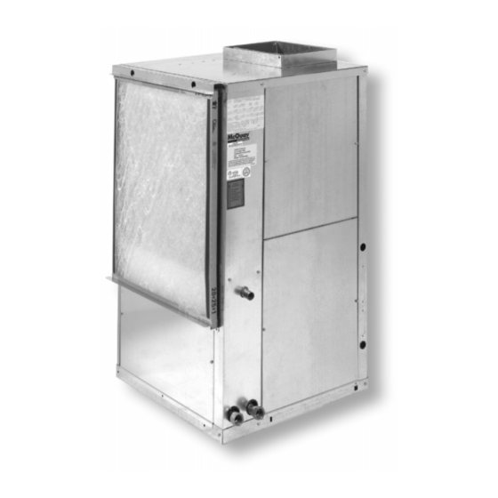
Vertical Water Source Heat Pump
& Cooling Only Units
Models FDD, FDE, FDL, FDS, FME, FMS
Model nomenclature ............................................................ 2
Transportation and shortage ................................................ 2
Installation ....................................................................... 2-4
Electrical data ...................................................................... 5
Piping ............................................................................... 5,6
Cleaning and flushing system .............................................. 6
Start-up ........................................................................... 6, 7
©2006 McQuay International
Installation & Maintenance Data
Contents
Operating limits ................................................................... 7
Wiring diagrams ............................................................. 8-14
Unit operation .................................................................... 15
LED Status and Fault Output Status .................................. 16
Thermostat Connections, Mark IV/AC units ....................... 17
Options for Mark IV/AC units ....................................... 19-22
Troubleshooting ................................................................. 23
Maintenance ...................................................................... 24
IM 407-16
Group: WSHP
Part Number: 106581203
Date: June 2006
®

Advertisement

Table of Contents
loading
Need help?

Need help?

Do you have a question about the FDD Series and is the answer not in the manual?

Questions and answers

Subscribe to Our Youtube Channel

Summary of Contents for McQuay FDD Series

  • Page 1: Table Of Contents

    LED Status and Fault Output Status ........16 Piping ................5,6 Thermostat Connections, Mark IV/AC units ....... 17 Cleaning and flushing system ..........6 Options for Mark IV/AC units ........19–22 Start-up ................6, 7 Troubleshooting ..............23 Maintenance ..............24 ® ©2006 McQuay International...
  • Page 2: Model Nomenclature

    019 = 19,000 M = 230-50-1 etc. . . N = 380-50-3 McQuay Product Identifiers FDD = Floor Mtd/DDC Controls/Ext. Range/Less Board FDS = Floor Mtd/DDC Controls/Std. Range FDE = Floor Mtd/DDC Controls/Ext. Range FME = Floor Mtd/Mark IV/Ext. Range FDL = Floor Mtd/DDC Controls/Std.
  • Page 3 5. It is recommended that the unit be located on top of a Unit location vibration absorbing material such as rubber or carpet to 1. Locate the unit in an area that allows for easy removal of reduce any vibration. See Figure 5. the filter and access panels, and has enough space for service personnel to perform maintenance or repair.
  • Page 4 Ductwork and attenuation Figure 2. Discharge ductwork is normally used with these condition- ers. Return air ductwork may also be required, but will require Trunk Duct field installation of a return air duct collar/2" (51mm) filter rack Square Elbow kit. (Both Sides Internally Lined All ductwork should conform to industry standards of...
  • Page 5: Electrical Data

    Electrical Data Disconnect and cap the red lead wire and interchange it with General the orange lead wire on the primary of the 24 volt trans- 1. Be sure the available power is the same voltage and phase former. Three-phase 50 cycle units require a neutral wire for as that shown on the unit serial plate.
  • Page 6: Cleaning And Flushing System

    Figure 5. Figure 6. Balancing Electrical Access Panel Blower Valve With Motor Close-off Access ⁄ " (38mm) Flexible Hose Supply Optional Cleanout With Brass Return Pipe Fitting Electrical & Compressor Access ⁄ " (38mm) Condensate ⁄ '' Per Foot Isolator Pad (21mm Per Meter) Note: Condensate drain connection must be minimum of 1"...
  • Page 7: Operating Limits

    Again, many conditioners have time delays which exceed 35 F (19 C). If the air temperature exceeds 35 protect the compressor against short cycling. After a C), the airflow rate is probably inadequate. few minutes of operation, check the discharge grilles for If the water temperature difference is less than 6 cool air delivery.
  • Page 8: Wiring Diagrams

    60 Cycle Wiring Diagrams — Mark IV/AC Units Figure 8. Unit sizes 007 through 012 (208-230, 265 volts, single-phase) 060686404 Rev. A Notes: 1. Mark IV/AC controller board contains a static sensitive micropro- cessor. Proper grounding of field service personnel is required or damage to controller may result.
  • Page 9 Figure 10. Unit sizes 019 through 048 (208-230, 265 volts, single-phase) 060686606 Rev. C Notes: 1. Mark IV/AC controller board contains a static sensitive micropro- cessor. Proper grounding of field service personnel is required or damage to controller may result. 2.
  • Page 10 Figure 12. Unit sizes 024 through 060 (208-230 volts, three-phase) 060686704 Rev. B Notes: 1. Mark IV/AC controller board contains a static sensitive micropro- cessor. Proper grounding of field service personnel is required or damage to controller may result. 2. Unit is factory wired for 230V operation. If 230V power supply is used, transformer must be rewired by disconnecting the power from the red transformer primary wire and connecting the power lead to the orange transformer primary wire.
  • Page 11 50 Cycle Wiring Diagrams — Mark IV/AC Units Figure 14. Unit sizes 007 through 012 (230 volts, single-phase) 061415316 Rev. A Notes: 1. Mark IV/AC controller board contains a static sensitive micropro- cessor. Proper grounding of field service personnel is required or damage to controller may result.
  • Page 12 Figure 16. Unit sizes 024 (230 volts, single-phase) 061415320 Rev. A Notes: 1. Mark IV/AC controller board contains a static sensitive micropro- cessor. Proper grounding of field service personnel is required or damage to controller may result. 2. Terminal block on Mark IV/AC board provides 24 VAC at termi- nals R and C.
  • Page 13 Figure 18. Unit sizes 024 through 042 (380 volts, three-phase) 061415321 Rev. A Notes: 1. Mark IV/AC controller board contains a static sensitive micropro- cessor. Proper grounding of field service personnel is required or damage to controller may result. 2. Terminal block on Mark IV/AC board provides 24 VAC at termi- nals R and C.
  • Page 14 Figure 20. Typical MicroTech 2000 WSHP unit controller single circuit wiring diagram Notes: 1. Unit is factory wired for 208V operation. If 230V power supply is used, transformer must be wired by disconnecting the power lead from the red transformer primary wire. Place an insulation cap on the red transformer primary wire.
  • Page 15: Unit Operation

    Unit Operation General Figure 29. Each unit has a printed circuit board control system. The low voltage output from the low voltage terminal strip on the control board is always 24 volts DC (direct current). Termi- nals R and C on the low voltage terminal strip supply 24 volts AC power.
  • Page 16: Led Status And Fault Output Status

    LED Status and Fault Output Status Read Outputs Board Status LED’s Fault Output Mode Yellow Green Terminal A Check Timers Occupied Energized Unoccupied Energized Ye s Pres. Sw ? Load Shed Energized Ye s Condensate Overflow De-Energized Brown Out ? High/Low Pressure Fault Flash De-Energized...
  • Page 17: Thermostat Connections, Mark Iv/Ac Units

    Thermostat Connection Diagrams Mark IV/AC Units – Unit Sizes 007 to 060 7-Day Programmable Electronic Thermostat (P/N 107095901) WSHP Mark IV/AC Board Low Voltage Terminal Strip (Circuit1) O W2 G W1 Y1 F Includes Thermostat and Wall Plate. Refer to the installation, operation & application guide (LIA217) for thermostat 107095901 installation details Non-Programmable Electronic Thermostat (P/N 668054201)
  • Page 18 Multiple Unit Control Panel for Mark IV Up to 3 Units (Part No. 056794201) This version of the board uses VAC relays and should not be used in combination with any other accessories or equipment The multiple unit control board is an accessory used when you that require VDC connections to the "G", "W1", or "Y1"...
  • Page 19: Options For Mark Iv/Ac Units

    Motorized Valve & Relay for Unit Sizes 007 to 060 Connector Wired as shown below the motorized valve will open on a call for compressor operation. Valves for unit sizes Valve 36" (915 mm) Black to 6 Lead Length 007 to 019 are ⁄...
  • Page 20 Boilerless System Kit (BSK) P/N 062522201 for Sizes 007 to 042 & P/N 062522204 for Sizes 048 to 060 The BSK option for use with the Mark IV/AC control board Normal/Override switch provides a means to manually force electric heat to always be used in place of heat pump heat provides the capability to control a remote duct heater.
  • Page 21 Pump Restart Relay Kit P/N 061419001 Used as an option with the Mark IV/AC board, the pump will change state causing a contact closure between terminal restart relay kit provides a means to alert the loop water 58 and 64 signaling the loop water control (LWC) panel to controller that water flow is required by a WSHP so that the restart the loop pump if Off.
  • Page 22 Field Installed Options on MicroTech 2000 Units MicroTech 2000 units can provide up to 4-outputs, that 4) Motorized Water Valve can be configured for any of the following output control These outputs provide control for a motorized water signals: valve that can be used to stop or divert flow away from the WSHP when compressor operation is not needed.
  • Page 23: Troubleshooting

    Troubleshooting Water Source Heat Pump WARNING To avoid electrical shock, personal injury or death, be sure that field wiring complies with local and national fire, safety, and electrical codes, and voltage to the system is within the limits shown in the job-specific drawings and unit electrical data plate(s). Power supply to unit must be disconnected when making field connections.
  • Page 24: Maintenance

    Warranty All McQuay equipment is sold pursuant to its standard terms and conditions of sale, including Limited Product Warranty. Consult your local McQuay Representative for warranty details. Refer to Form 933-43285Y. To find your local McQuay Representative, go to www.mcquay.com.

This manual is also suitable for:

Fde seriesFdl seriesFds seriesFme seriesFms series

Table of Contents

Save PDF