
Subscribe to Our Youtube Channel
Related Manuals for McQuay MWH011B


Summary of Contents for McQuay MWH011B
- Page 1 MWH-B-2005 Horizontal Water Source Heat Pumps And Cooling Only Unit Models: MWH 011 B/BR MWH 030 B/BR MWH 012 B/BR MWH 040 B/BR MWH 015 B/BR MWH 050 B/BR MWH 020 B/BR MWH 060 B/BR MWH 025 B/BR MWH 070 B/BR...
-
Page 2: Table Of Contents
"McQuay" is a registered trademark of McQuay International. All rights reserved throughout the world. 2005 McQuay International "Bulletin illustrations cover the general appearance of McQuay International products at the time of publication and we reserve the right to make changes in design and construction at any time without notice."... -
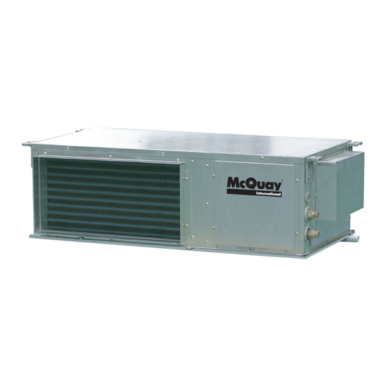
Page 3: Features
MWH025 and above), coil, tube in tube heat exchanger, expansion device and forward curved centrifugal blower. All units in this series have a very low profile, from 250mm for the MWH011B/BR, which has a horizontal compressor, to the largest unit in the range at 500mm. -
Page 4: Nomenclature
Nomenclature nil - Cooling Only Brand Name Nominal (McQuay) Cooling Capacity R - Heat Pump Water Source Generation Heat Pump... -
Page 5: Specifications
Specifications Cooling only MODEL MWH011B MWH012B MWH015B MWH020B MWH025B NOMINAL COOLING CAPACITY Btu/h 11600 12000 14400 19500 26000 EFFECTIVE INPUT POWER (COOLING) 1210 1450 1720 NOMINAL INPUT POWER 1253 1561 1894 NOMINAL RUNNING CURRENT COP (COOLING) POWER SOURCE V/Ph/Hz 220-240 / 1 / 50... - Page 6 Cooling only MODEL MWH030B MWH040B MWH050B MWH060B MWH070B 13.2 14.6 18.5 22.4 NOMINAL COOLING CAPACITY Btu/h 29920 44870 49880 63160 76460 NOMINAL INPUT POWER (COOLING) 2485 3897 4482 5505 6041 NOMINAL RUNNING CURR. (COOLING) 11.9 18.6 21.6 13.3 14.8 COP (COOLING) POWER SOURCE V/Ph/Hz 220-240 / 1 / 50...
- Page 7 Heat Pump MODEL MWH011BR MWH012BR MWH015BR MWH020BR MWH025BR NOMINAL COOLING CAPACITY Btu/h 11600 12000 14400 19500 26000 NOMINAL HEATING CAPACITY Btu/h 13000 12700 14800 17000 28800 EFFECTIVE INPUT POWER (COOLING) 1210 1550 1720 EFFECTIVE INPUT POWER (HEATING) 1110 1250 1670 NOMINAL INPUT POWER (COOLING) 1253 1661...
-
Page 8: Specifications
Heat Pump MODEL MWH030BR MWH040BR MWH050BR MWH060BR MWH070BR 13.2 14.6 18.5 22.4 NOMINAL COOLING CAPACITY Btu/h 29920 44870 49880 63160 76460 15.1 16.6 20.0 22.4 NOMINAL HEATING CAPACITY Btu/h 31600 51520 56500 68140 76460 NOMINAL INPUT POWER (COOLING) 2485 3897 4482 5505 6041... -
Page 9: Operating Range
Operation Range Heating Cooling 21.1 29.4 21.1 19.4 Indoor temp. (°CDB) Indoor temp. (°CWB) -
Page 10: Noise Level
1/1 Octave Sound Pressure Level (dB, ref 20μPa) Overall Noise Model Speed 125 Hz 250 Hz 500 Hz 1 kHz 2 kHz 4 kHz 8 kHz A (dBA) Criteria S.High High MWH011B/BR Medium S.High High MWH012B/BR Medium S.High High MWH015B/BR Medium S.High High MWH020B/BR Medium S.High... -
Page 11: Performance Table
S (kW) T (Kw) S (kW) T (Kw) S (kW) 3.109 2.596 3.100 2.483 3.091 2.370 3.181 2.469 0.510 2.454 0.510 2.454 MWH011B 3.606 2.940 3.503 2.940 3.400 2.940 3.400 2.822 0.544 2.704 0.544 2.704 3.594 3.161 3.600 3.161 3.606 3.161... - Page 12 Heat pump - Heat mode Coil E.A.T. Leaving Water Temperature °C (L.W.T.) Model °C DB T (kW) T (kW) T (kW) 3.474 3.800 4.126 MWH011BR 3.474 3.800 4.126 3.474 3.800 4.126 3.383 3.700 4.017 MWH012BR 3.383 3.700 4.017 3.383 3.700 4.017 3.993 4.300...
-
Page 13: Fan Performance Table
Fan Performance Curve MWH011B/BR External Static Pressure vs Air Flow Rate Super High Speed High Speed Medium Speed Low Speed Air Flow Rate (L/s) - Page 14 MWH012B/BR External Static Pressure vs Air Flow Rate Super High Speed High Speed Medium Speed Low Speed Air Flow Rate (L/s)
- Page 15 MWH015B/BR External Static Pressure vs Air Flow Rate Super High Speed High Speed Medium Speed Low Speed Air Flow Rate (L/s)
- Page 16 MWH020B/BR External Static Pressure vs Air Flow Rate Super High Speed High Speed Medium Speed Low Speed Air Flow Rate (L/s)
- Page 17 MWH025B/BR External Static Pressure vs Air Flow Rate Super High Speed High Speed Medium Speed Low Speed Air Flow Rate (L/s)
- Page 18 MWH030B/BR External Static Pressure vs Air Flow Rate Low Speed High Speed Medium Speed Air Flow Rate (L/s)
- Page 19 MWH040B/BR External Static Pressure vs Air Flow Rate Medium Speed Low Speed High Speed Air Flow Rate (L/s)
- Page 20 MWH050B/BR External Static Pressure vs Air Flow Rate Medium Speed High Speed Low Speed Air Flow Rate (L/s)
- Page 21 MWH060B/BR External Static Pressure vs Air Flow Rate High Speed Medium Speed Low Speed 1050 Air Flow Rate (L/s)
- Page 22 MWH070B/BR External Static Pressure vs Air Flow Rate High Speed Medium Speed Low Speed 1050 1150 1250 Air Flow Rate (L/s)
-
Page 23: Outline Dimension
Outline Dimension Model : MWH011/015/020/025 B/BR Model MWH011B/BR 250.0 1084.0 547.0 174.0 502.0 28.5 36.5 396.0 586.0 1026.0 32.0 40.0 29.0 195.5 MWH012B/BR 325.0 1072.0 552.0 248.0 542.0 29.5 36.5 401.0 626.0 1046.0 60.0 65.0 35.0 269.5 MWH015B/BR 337.0 1072.0 552.0... - Page 24 Model : MWH030B/BR POW ER I NLET O 25 1297. 2 1217 S YS 1 HI GH PRES S URE 1161. 2 DRAI NI NG I N G3/4″ MAI NTAI N PANEL OUT G3/4″ DRAI NI NG 68. 7 Model : MWH040B/BR,MWH050B/BR 246.
- Page 25 Model : MWH060B/BR, MWH070B/BR...
-
Page 26: Wiring Diagrams
Wiring Diagrams Model : MWH011/012/015B Model : MWH011/012/015B (Heater) - Page 27 Model : MWH020B Model : MWH020B (Heater)
- Page 28 Model : MWH025B Model : MWH025B (Heater)
- Page 29 Model : MWH030B MODE L : MWH030BD (Heater)
- Page 30 MODE L : MWH040/050B MODE L : MWH040/050BD(Heater)
- Page 31 MODE L : MWH060B MODEL: SYMBOL DESCRI PTI ON SYMBOL DESCRI PTI ON THERMAL OVERLOAD RELAY SETTI NG AMPS AND CONTROLLER JP SETTI NG MODEL LEGEND: FI ELD W I RI NG FACTORY W I RED MODE L : MWH060BD (Heater) SYMBOL DESCRI PTI ON SYMBOL...
- Page 32 MODE L : MWH070B SYMBOL DESCRI PTI ON SYMBOL DESCRI PTI ON THERMAL OVERLOAD RELAY SETTI NG AMPS AND CONTROLLER JP SETTI NG MODEL LEGEND: FI ELD W I RI NG FACTORY W I RED MODE L : MWH070BD (Heater) SYMBOL DESCRI PTI ON SYMBOL...
- Page 33 Model : MWH011/012/015BR Model : MWH011/012/015BR (Heater)
- Page 34 Model : MWH020BR Model : MWH020BR (Heater)
- Page 35 Model : MWH025BR Model : MWH025BR (Heater)
- Page 36 Model : MWH030BR M ODEL: M W H030BR MODEL: MW H040/050BR Model : MWH040/050BR...
- Page 37 Model : MWH060BR M ODEL: SYM BOL DESCRI PTI ON SYM BOL DESCRI PTI ON THERM AL OVERLOAD RELAY SETTI NG AM PS AND COTROLLER JP SETTI NG MODEL LEGEND: FI ELD W I RI NG FACTORY W I RED Model : MWH070BR MODEL: SYMBOL...
-
Page 38: Refrigerant Diagrams
Refrigerant Diagrams MWH011/012/015/020B MWH025B... - Page 39 MWH011/012/015/020BR MWH025BR...
- Page 40 MWH030/040/050B H P 2 WATER OUTLET H P 1 CHENCK JOINT FAN MOTOR CHENCK CHENCK CHENCK JOINT JOINT JOINT COIL TUBE IN TUBE IN SEPARATOR SEPARATOR TUBE 2 TUBE 1 WATER INLET COMPRESSOR 2 COMPRESSOR 1 COOLING CAP. TUBE STRAINER STRAINER COOLING CAP.
- Page 41 MWH060/070B H P 2 WATER OUTLET H P 1 FAN MOTOR CHENCK CHENCK JOINT JOINT COIL TUBE IN TUBE IN CHENCK TUBE 2 TUBE 1 JOINT CHENCK JOINT WATER INLET COMPRESSOR 2 COMPRESSOR 1 COOLING CAP. TUBE STRAINER STRAINER COOLING CAP. TUBE STRAINER STRAINER COOLING OPERATION...
-
Page 42: Safety Precaution Before Installation
SAFETY PRECAUTIONS BEFORE INSTALLATION... -
Page 43: Installation
INSTALLATION... -
Page 45: Controller Error Code
CONTROLLER ERROR CODE... -
Page 46: Servicing And Maintenance
SERVICING AND MAINTENANCE... -
Page 47: Troubleshooting
TROUBLESHOOTING... -
Page 48: Overall Checking
Overall Checking Ensure that: 1) The unit has been mounted solidly and rigid in position. 2) The piping and connections are leak-proof. 3) Proper wiring has been installed. Drainage Check Pour some water into the left side of the drain pan (the drainage is at the right side of the unit). Test run: 1) Conduct a test run on the unit after having performed the water drainage test and the gas leakage test. -
Page 49: Cleaning System Flushing
Additionally, the heat exchanger may become clogged which reduces compressor service life or causes premature failure. A System Saver® from McQuay International should be employed to continuously remove solids as the system operates. Contact your local representative for further information on this device. -
Page 50: Startup
Startup Open all valves to full open position and turn on power to the conditioner. 1. Set mode to “Cool”. Set the cooling temperature to the coolest position. Again, many conditioners have time delays which protect the compressor(s) against short cycling. After a few minutes of operation, check the discharge grilles for cool air delivery. -
Page 51: Part Lists
Part List Model : MWH011B Description Description Assy., Ins. Drain Pan Assy., Filter Flange Assy., Ins. Front Panel Assy., Ins. Service Panel Assy., Ins. Back Panel Motor Assy., Coil Hanger Bracket Assy., Lower Base Panel Assy., Ins. Top Panel Assy., Ins. Fan Deck Hanger Assy., Ins. - Page 52 Model : MWH012/15B Description Description Assy., Ins. Drain Pan Duct Flange Assy., Ins. Front Panel Assy., Fan Deck Support Assy., Ins. Back Panel Assy., Filter Flange Assy., Coil Assy., Ins. Service Panel Assy., Lower Base Panel Assy., Ins. Top Panel Assy., Ins.
- Page 53 Model : MWH020B Part Description Part Description Assy., Ins. Drain Panel Assy., Ins. Front Service Panel Assy., Ins. Front Panel Assy., Ins. Top Panel Assy., Ins. Back Panel Assy., Ins. Right Service Panel Assy., Coil Hanger Bracket Assy., Ins. Comp. Base Lower Assy., Unit Tubing Assy., Ins.
- Page 54 Model : MWH025B Part Description Part Description Assy., Ins. Drain Panel Assy., Fan Deck Support Assy., Ins. Front Panel Assy., Ins. Front Service Panel Assy., Ins. Back Panel Assy., Ins. Top Panel Assy., Coil Assy., Ins. Right Service Panel Assy., Ins. Comp. Base Lower Hanger Bracket Assy., Ins.
- Page 55 Model : MWH030B PART DESCRIPTION PART DESCRIPTION ASSY.COMPRESSOR ASSY. MIDDLE LEFT PANEL SUPPORT PANEL ASSY. FRONT RIGHT PANEL ASSY. MAINTAIN PANEL COMPRESSOR ASSY. WELD HOOK ASSY.BASE ASSY. BLOWER & MOTOR ASSY. CONTROL BOX ASSY. MIDDLE PANEL ASSY. CONDENDER ASSY. TUBE UNIT 2 ASSY.
- Page 56 Model : MWH040/050B PART DESCRIPTION PART DESCRIPTION ASSY.COMPRESSOR ASSY. MIDDLE LEFT PANEL SUPPORT PANEL ASSY. FRONT RIGHT PANEL ASSY. MAINTAIN PANEL COMPRESSOR ASSY. WELD HOOK ASSY.BASE ASSY. BLOWER & MOTOR ASSY. CONTROL BOX ASSY. MIDDLE PANEL ASSY. CONDENDER ASSY. TUBE UNIT 2 ASSY.
- Page 57 Model : MWH060/070B PART DESCRIPTION PART DESCRIPTION ASSY. CONTROL COIL ASSEMBLY BOX ASSEMBLY ASSY.COMPRESSOR ASSY. FILTER SUPPORT PANEL SUPPORT PANEL TOP AND BOTTOM ASSY. BASE PANEL TUBE(1 SUIT) ASSY. BOTTOM CHECK PANEL ASSY. TOP PANEL ASSY. WELD HOOK ASSY. CHECK PANEL BACK ASSY.
- Page 58 Model : MWH011BR Description Description Assy., Ins. Drain Pan Assy., Filter Flange Assy., Ins. Front Panel Assy., Ins. Service Panel Assy., Ins. Back Panel Motor Assy., Coil Hanger Bracket Assy., Lower Base Panel Assy., Ins. Top Panel Assy., Ins. Fan Deck Hanger Assy., Ins.
- Page 59 Model : MWH012/15BR Description Description Assy., Ins. Drain Pan Duct Flange Assy., Ins. Front Panel Assy., Fan Deck Support Assy., Ins. Back Panel Assy., Filter Flange Assy., Coil Assy., Ins. Service Panel Assy., Lower Base Panel Assy., Ins. Top Panel Assy., Ins.
- Page 60 Model : MWH020BR Part Description Part Description Assy., Ins. Drain Panel Assy., Ins. Front Service Panel Assy., Ins. Front Panel Assy., Ins. Top Panel Assy., Ins. Back Panel Assy., Ins. Right Service Panel Assy., Coil Hanger Bracket Assy., Ins. Comp. Base Lower Assy., Unit Tubing Assy., Ins.
- Page 61 Model : MWH025BR Part Description Part Description Assy., Ins. Drain Panel Assy., Fan Deck Support Assy., Ins. Front Panel Assy., Ins. Front Service Panel Assy., Ins. Back Panel Assy., Ins. Top Panel Assy., Coil Assy., Ins. Right Service Panel Assy., Ins. Comp. Base Lower Hanger Bracket Assy., Ins.
- Page 62 Model : MWH030BR PART DESCRIPTION PART DESCRIPTION ASSY.COMPRESSOR ASSY. MIDDLE LEFT PANEL SUPPORT PANEL ASSY. FRONT RIGHT PANEL ASSY. MAINTAIN PANEL COMPRESSOR ASSY. WELD HOOK ASSY.BASE ASSY. BLOWER & MOTOR ASSY. CONTROL BOX ASSY. MIDDLE PANEL ASSY. CONDENDER ASSY. TUBE UNIT 2 ASSY.
- Page 63 Model : MWH040BR/050BR PART DESCRIPTION PART DESCRIPTION ASSY.COMPRESSOR ASSY. MIDDLE LEFT PANEL SUPPORT PANEL ASSY. FRONT RIGHT PANEL ASSY. MAINTAIN PANEL COMPRESSOR ASSY. WELD HOOK ASSY.BASE ASSY. BLOWER & MOTOR ASSY. CONTROL BOX ASSY. MIDDLE PANEL ASSY. CONDENDER ASSY. TUBE UNIT 2 ASSY.
- Page 64 Model : MWH060BR/070BR PART DESCRIPTION PART DESCRIPTION ACCUMULATOR COIL ASSEMBLY ASSY.COMPRESSOR ASSY. FILTER SUPPORT PANEL SUPPORT PANEL TOP AND BOTTOM ASSY. BASE PANEL TUBE(1 SUIT) ASSY. BOTTOM CHECK PANEL ASSY. TOP PANEL ASSY. WELD HOOK ASSY. CHECK PANEL BACK ASSY. FRONT CHECK PANEL FILTER ASSY.
- Page 65 REGISTERED S&E ISO 9002 ©2005 McQuay International +1 (800) 432-1342 www.mcquay.com...
Need help?
Do you have a question about the MWH011B and is the answer not in the manual?
Questions and answers