Table of Contents
Advertisement
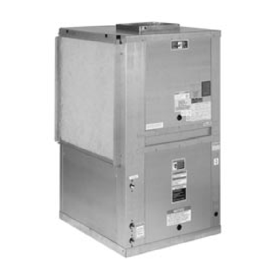
McQuay
®
Enfinity
Vertical Water Source Heat Pumps
Unit Sizes 007 - 012 / R-22 Refrigerant
Unit Sizes 019 - 060 / R-410A Refrigerant
Model Nomenclature . . . . . . . . . . . . . . . . . . . . . . . . . . 2
Transportation & Storage . . . . . . . . . . . . . . . . . . . . . . . 2
Installation . . . . . . . . . . . . . . . . . . . . . . . . . . . . . . . . 2-4
Electrical Data . . . . . . . . . . . . . . . . . . . . . . . . . . . . . . . 5
Piping . . . . . . . . . . . . . . . . . . . . . . . . . . . . . . . . . . . . . 5
Cleaning & Flushing System . . . . . . . . . . . . . . . . . . . . 6
Start-up. . . . . . . . . . . . . . . . . . . . . . . . . . . . . . . . . . . . 7
Operating Limits . . . . . . . . . . . . . . . . . . . . . . . . . . . . . 8
Typical Wiring Diagrams . . . . . . . . . . . . . . . . . . . . . 9-11
Installation & Maintenance Data
™
Contents
©2006 McQuay International
Unit Operation . . . . . . . . . . . . . . . . . . . . . . . . . . . 12-14
Thermostat Connections . . . . . . . . . . . . . . . . . . . . . . 16
Options for Mark IV/AC Units . . . . . . . . . . . . . . . . 17-21
Field Installed Options on MicroTech Units . . . . . . . . 22
Sequence of Operation . . . . . . . . . . . . . . . . . . . . . . . 23
Troubleshooting WSHP. . . . . . . . . . . . . . . . . . . . . 24-25
Maintenance . . . . . . . . . . . . . . . . . . . . . . . . . . . . . . . 25
Troubleshooting Refrigeration Circuit . . . . . . . . . . . . . 26
IM 778-2
Group: WSHP
Part Number: 106751103
Date: June 2006
®
Advertisement
Table of Contents

Related Manuals for McQuay Enfinity series


Summary of Contents for McQuay Enfinity series
-
Page 1: Table Of Contents
Troubleshooting Refrigeration Circuit ... . . 26 Typical Wiring Diagrams ..... 9-11 ® ©2006 McQuay International... -
Page 2: Model Nomenclature
Model Nomenclature Note: For illustration purposes only. Not all options available with all models. Please consult McQuay Sales Representative for specific availability. Product Category Discharge Air W = WSHP T = Top Product Identifier Return Air FCV = Floor Mounted/Standard Range... -
Page 3: Unit Location
Unit location 5. It is recommended that the unit be located on top of a vibration absorbing material such as rubber or carpet to 1. Locate the unit in an area that allows for easy removal of reduce any vibration. See Figure 8, page 6. the filter and access panels, and has enough space for 6. - Page 4 Figure 3. Ductwork and attenuation Discharge ductwork is normally used with these condi- Trunk Duct tioners. Return air ductwork may also be required, but will Square Elbow require field installation of a return air duct collar/2" (51mm) (Both Sides filter rack kit. Internally Lined With Acoustic All ductwork should conform to industry standards of...
-
Page 5: Electrical Data
Electrical Data General breaker for branch circuit overcurrent protection. See the 1. Verify the compatibility between the voltage and phase nameplate for correct ratings. of the available power and that shown on the unit serial plate. Line and low voltage wiring must comply with local 3. -
Page 6: Cleaning & Flushing System
Do not locate any point in the drain system above the Figure 8. Typical Vertical Unit Piping drain connection of any unit. 10. Automatic flow controlled devices must not be Supply Air Acoustical Thermal installed prior to system cleaning and flushing. Duct Lining (10’) 11. -
Page 7: Start-Up
5. Refill the system with clean water. Test the water using es premature failure. A SystemSaver from McQuay ™ litmus paper for acidity, and treat as required to leave the should be employed to continuously re-move solids as water slightly alkaline (pH 7.5 to 8.5). The specified per- the system operates. -
Page 8: Operating Limits
Operating Limits Environment This equipment is designed for indoor installation only. temperature and/or humidity, and equipment performance, Sheltered locations such as attics, garages, etc., generally reliability, and service life may be adversely affected. will not provide sufficient protection against extremes in Air limits Water limits Standard Range... -
Page 9: Typical Wiring Diagrams
Typical Wiring Diagrams Figure 10. Typical Mark IV/AC wiring diagram Notes: 1. Unit is factory wired for 208V operation. If 230V power supply is used, transformer must be rewired by disconnecting the power lead from the red transformer primary wire and connecting the power lead to the orange transformer primary wire. - Page 10 Figure 11. Typical MicroTech 2000 WSHP unit controller single circuit wiring diagram Notes: 1. Unit is factory wired for 208V operation. If 230V power supply is used, 2. All temperature and pressure switches are normally closed. transformer must be rewired by disconnecting the power lead from the 3.
- Page 11 Figure 12. Typical BACnet ® WSHP unit controller Notes: 1. Unit is factory wired for 208V operation. If 230V power supply is used, transformer must be rewired by disconnecting the power lead from the red transformer primary wire and connecting the power lead to the orange transformer primary wire.
-
Page 12: Unit Operation
Unit Operation Three types of units are available: Mark IV/AC control units or units equipped with a MicroTech™ 2000 or BACnet ® Water Source Heat Pump Controller. Mark IV/AC Control Units The Mark IV/AC circuit board is an optional control sys- The Remote Reset feature provides the means to tem with built-in features such as random start, compressor remotely reset automatic lockouts generated by high-pres-... - Page 13 MicroTech™ 2000 WSHP Unit Controller An amber, on-board status LED aids in diagnostics by indi- Each McQuay Enfinity vertical water source heat pump can be equipped with a MicroTech 2000 water source heat pump cating the water source heat pump operating mode and alarm conditions.
- Page 14 ® WSHP Unit Controller Each BACnet-compliant controller has the following operat- McQuay Enfinity vertical water source heat pumps are ing features: available with a factory mounted and tested Alerton BACnet unit controller as a special. The unit controller is factory pro- Start-up –...
- Page 15 BACnet ® WSHP Unit Controller temperature is within setpoints. The controller also mon- Condensate Overflow Protection – A liquid sensor at itors leaving water temperature. If the leaving water tem- the top of the drain pan senses a high water level. Upon perature is outside software-configurable setpoints, com- sensing water, cooling operation is suspended, while pressor operation is suspended and high or low water...
-
Page 16: Thermostat Connections
Thermostat Connection Diagrams Mark IV/AC Units – Unit Sizes 007-060 7-Day Programmable Electronic Thermostat (P/N 107095901) WSHP Mark IV/AC Board Low Voltage Terminal Strip (Circuit1) O W2 G W1 Y1 F Includes Thermostat and Wall Plate. Refer to the installation, operation & application guide (LIA217) for thermo- stat 107095901 installation details Non-Programmable Electronic Thermostat (P/N 668054201) -
Page 17: Options For Mark Iv/Ac Units
Options on Mark IV/AC Units Auxiliary Relay (P/N 106059701) The auxiliary relay is designed to interface external equip- WSHP Mark IV/AC Board Low Voltage Terminal Strip ment with the Mark IV/AC board. The auxiliary relay O W2 G W1 Y1 F has been provided with the components necessary to protect from electrical damage that may occur to the Mark IV/AC board when using standard off-the-self relays. - Page 18 Multiple Unit Control (up to 3 units) (P/N 056794201) This multiple unit control board is an accessory used when or “Y1” terminals (i.e. Boilerless System Kit). you need to control up to 3-units from a single thermostat. The multiple unit control board provides the components The board is typically mounted in the unit control box clos- necessary to protect the Mark IV/AC board from electrical est to the thermostat.
- Page 19 Motorized Valve & Relay for Unit Sizes 007 thru 060 Wired as shown below the motorized valve will open on a Note: The wiring shown below can only be used when the “P” ter- minal is not being used as a pump restart signal to other equip- call for compressor operation.
- Page 20 Boilerless System Kit (BSK) – P/N 062522204 for sizes 007 - 060 The BSK option for use with the Mark IV/AC control board provides the capability to control a remote duct heater. The duct heater must be provided with a low voltage control circuit that only requires a set of dry contacts for operation.
- Page 21 Pump Restart Relay Kit P/N 061419001 Used as an option with the Mark IV/AC board, the pump will change state causing a contact closure between termi- restart relay kit provides a means to alert the loop water nal 58 and 64 signaling the loop water control (LWC) panel controller that water flow is required by a WSHP so that the to restart the loop pump if Off.
-
Page 22: Field Installed Options On Microtech Units
Field Installed Options on MicroTech 2000 Units MicroTech 2000 units can provide up to 4-outputs, that can 4) Motorized Water Valve be configured for any of the following output control These outputs provide control for a motorized water signals: valve that can be used to stop or divert flow away from the WSHP when compressor operation is not needed. -
Page 23: Sequence Of Operation
Mark IV/AC Sequence of Operation Read Outputs Check Timers 14-Position Terminal Strip Ye s Pres. Sw ? Designation Description Transformer ground (Ovac) Ye s Brown Out ? Transformer supply (24vac) -DC power connection Pump request output Ye s Low Temp Sw ? Alarm fault output Unoccupied input Ye s... -
Page 24: Troubleshooting Wshp
Troubleshooting Water Source Heat Pump DANGER Field wiring must comply with local and national fire, safety, and electrical codes, and voltage to the system must be within the limits shown in the job-specific drawings and unit electrical data plate(s). All power supply to unit must be disconnected when making field connections. Rigorously adhere to lockout and tagout procedures. Improper wiring or procedure can cause electric, personal injury or death. -
Page 25: Maintenance
All McQuay water source heat pumps are Lubrication designed for commercial use. The units are designed for the cooling mode of operation and fail safe to cooling. -
Page 26: Troubleshooting Refrigeration Circuit
Troubleshooting Refrigeration Circuit Water Safety Head Suction Compressor Super Temp (loops) Temp Lock Symptom Pressure Pressure Amp Draw Heat Subcooling Differential Differential Charge Undercharge System High Low Pressure (Possible Leak) Normal Overcharge System High High High Normal High Normal High Pressure High Low Air Flow Heating High... - Page 27 McQuay Training and Development Now that you have made an investment in modern, efficient McQuay equipment, its care should be a high priority. For training information on all McQuay HVAC products, please visit us at www.mcquay.com and click on training, or call 540-248-9646 and ask for the Training Department.
Need help?
Do you have a question about the Enfinity series and is the answer not in the manual?
Questions and answers