Table of Contents
Advertisement
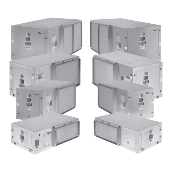
McQuay
Enfinity
®
Horizontal Water Source Heat Pumps
Model CRH, CRW Unit Sizes 007 - 070 / R-22 Refrigerant
Model CCH, CCW Unit Sizes 007 - 060 / R-410A Refrigerant
Model Nomenclature . . . . . . . . . . . . . . . . . . . . . . . . . . . 2
Transportation & Storage . . . . . . . . . . . . . . . . . . . . . . . . 2
Installation . . . . . . . . . . . . . . . . . . . . . . . . . . . . . . . . . .2-4
Electrical Data . . . . . . . . . . . . . . . . . . . . . . . . . . . . . . . . 5
Piping . . . . . . . . . . . . . . . . . . . . . . . . . . . . . . . . . . . . . . . 5
Cleaning & Flushing System . . . . . . . . . . . . . . . . . . . . . 6
Start-up . . . . . . . . . . . . . . . . . . . . . . . . . . . . . . . . . . . . . . 7
Operating Limits . . . . . . . . . . . . . . . . . . . . . . . . . . . . . . . 8
Typical Wiring Diagrams . . . . . . . . . . . . . . . . . . . . . . .9-11
Installation & Maintenance Data
(R-410A) and Standard (R-22)
™
Contents
©2007 McQuay International
Unit Operation . . . . . . . . . . . . . . . . . . . . . . . . . . . . .12-14
Thermostat Connections . . . . . . . . . . . . . . . . . . . . .16-17
Options for Mark IV/AC Units . . . . . . . . . . . . . . . . . .18-21
Field Installed Options on MicroTech Units . . . . . . . . . 22
Sequence of Operation . . . . . . . . . . . . . . . . . . . . . . . . 23
Troubleshooting WSHP . . . . . . . . . . . . . . . . . . . . . .24-25
Troubleshooting Refrigeration Circuit . . . . . . . . . . . . . . 25
Typical Refrigeration Cycles . . . . . . . . . . . . . . . . . . . . . 26
General Maintenance . . . . . . . . . . . . . . . . . . . . . . . . . . 27
IM 742-4
Group: WSHP
Part Number: 106586605
Date: September 2007
®
Advertisement
Table of Contents
Troubleshooting

Related Manuals for McQuay Enfinity CRH series


Summary of Contents for McQuay Enfinity CRH series
-
Page 1: Table Of Contents
General Maintenance . . . . . . . . . . . . . . . . . . . . . . . . . . 27 ® ©2007 McQuay International... -
Page 2: Model Nomenclature
Model Nomenclature Note: For illustration purposes only . Not all options available with all models . Please consult McQuay Sales Representative for specific availability . Product Catagory Discharge Air S = Straight W = WSHP E = End Return Air... -
Page 3: Unit Location
Unit Location 1 . Locate the unit in an area that allows for easy removal Figure 1B. Unit sizes 007 thru 070 of the filter and access panels . Leave a minimum of 18” of clearance around the heat pump for easy removal, and to perform routine maintenance, or troubleshooting . -
Page 4: Ventilation Air
Air Discharge Conversion Unit sizes 007 thru 070 can be shipped as straight discharge air discharge the housing is bottom horizontal and with air or end discharge air arrangement . In the event that the an end discharge the housing is top horizontal . unit needs to be converted from straight discharge to end 4 . -
Page 5: Electrical Data
Electrical Data General 1 . Verify the compatibility between the voltage and phase breaker for branch circuit overcurrent protection . See the of the available power and that shown on the unit serial nameplate for correct ratings . plate . Line and low voltage wiring must comply with 3 . -
Page 6: Cleaning & Flushing System
7 . Condensate piping can be steel, copper or PVC . Each used . Union fittings in the copper or PVC lines should unit includes a condensate connection . be applied to facilitate removal . 8 . The condensate disposal piping must be trapped . The Do not locate any point in the drain system above the piping must be pitched away from the unit not less than drain connection of any unit . -
Page 7: Start-Up
5 . Refill the system with clean water . Test the water using 6 . Set the loop water controller heat add setpoint to 70°F litmus paper for acidity, and treat as required to leave the (21°C) and the heat rejection setpoint to 85°F (29°C) . water slightly alkaline (pH 7 .5 to 8 .5) . -
Page 8: Operating Limits
Operating Limits Environment This equipment is designed for indoor installation only . temperature and/or humidity, and equipment performance, Sheltered locations such as attics, garages, etc ., gener- reliability, and service life may be adversely affected . ally will not provide sufficient protection against extremes in Air limits Water limits Geothermal Range... -
Page 9: Typical Wiring Diagrams
Typical Wiring Diagrams Figure 8. Typical Mark IV/AC wiring diagram Ground COMPONENT LAYOUT ➀ COMPRESSOR CONTACTOR ➁ FAN CONTACTOR ➂ TRANSFORMER Compr ➃ PC BOARD Motor ➄ AUXILIARY RELAY ➅ CIRCUIT BREAKER Heater 070 - Blk 060 - Blk 048 - Red Motor 042 - Blk 036 - Blk... - Page 10 Figure 9. Typical MicroTech 2000 WSHP unit controller single circuit wiring diagram Notes: 2 . All temperature and pressure switches are normally closed . 1 . Unit is factory wired for 208V operation . If 230V power supply is used, transformer must be rewired by disconnecting the power lead from the 3 .
- Page 11 Figure 10. Typical BACnet WSHP unit controller ® BACnet Controller Notes: 1. A 208/230V unit is factory wired for 208V operation. If 230V power Notes: supply used, transformer must rewired disconnecting the power lead from the red transformer primary wire and connecting 1 .
-
Page 12: Unit Operation
Unit Operation Two types of units are available: Mark IV/AC control units or units equipped with the new MicroTech 2000 Water Source Heat Pump Controller . Mark IV/AC Control Units The Mark IV/AC circuit board is an optional control sys- The Remote Reset feature provides the means to tem with built-in features such as random start, compressor remotely reset automatic lockouts generated by high-pres-... -
Page 13: Unit Operation
MicroTech™ 2000 WSHP Unit Controller Each McQuay Enfinity R-410A and standard R-22 horizontal An amber, on-board status LED aids in diagnostics by water source heat pump can be equipped with a MicroTech indicating the water source heat pump operating mode and 2000 water source heat pump unit controller . - Page 14 BACnet WSHP Unit Controller ® McQuay Enfinity horizontal water source heat pumps Each BACnet-compliant controller has the following operat- are available with a factory mounted and tested Alerton ing features: BACnet unit controller as a special . The unit controller is Start-up –...
- Page 15 BACnet WSHP Unit Controller ® Condensate Overflow Protection – A liquid sensor at temperature is within setpoints . The controller also ● the top of the drain pan senses a high water level . Upon monitors leaving water temperature . If the leaving water temperature is outside software-configurable setpoints, sensing water, cooling operation is suspended, while compressor operation is suspended and high or low...
-
Page 16: Thermostat Connections
Thermostat Connection Diagrams Mark IV/AC Units – Unit Sizes 007-070 7-Day Programmable Electronic Thermostat (P/N 107095901) WSHP Mark IV/AC Board Low Voltage Terminal Strip (Circuit 1) O W2 G W1 Y1 F Includes Thermostat and Wall Plate . Refer to the installation, operation & application guide (LIA217) for thermostat 107095901 installa- tion details Non-Programmable Electronic Thermostat (P/N 668054201) - Page 17 MicroTech Wall Sensor – Wiring Diagram Locate the sensor on a wall where exposure to unrestrict- ed air circulation represents the average temperature of MicroTech Controller the space . A common mistake is to mount the sensor too 9 10 11 12 close to the supply air diffuser in a room .
-
Page 18: Options For Mark Iv/Ac Units
Options on Mark IV/AC Units Auxiliary Relay (P/N 106059701) The auxiliary relay is designed to interface external equip- WSHP Mark IV/AC Board Low Voltage Terminal Strip ment with the Mark IV/AC board . The auxiliary relay O W2 G W1 Y1 F has been provided with the components necessary to protect from electrical damage that may occur to the Mark IV/AC board when using standard off-the-self relays . - Page 19 Multiple Unit Control (up to 2 units) (P/N 106059801) This multiple unit control board is an accessory used when or equipment that require VAC connections to the “G”, “W1”, you need to control up to 2-units from a single thermostat . or “Y1”...
- Page 20 Boilerless System Kit (BSK) – P/N 062522204 for sizes 007 - 070 The BSK option for use with the Mark IV/AC control board provides the capability to control a remote duct heater . The duct heater must be provided with a low voltage control cir- cuit that only requires a set of dry contacts for operation .
- Page 21 Pump Restart Relay Kit P/N 061419001 Used as an option with the Mark IV/AC board, the pump will change state causing a contact closure between terminal restart relay kit provides a means to alert the loop water 58 and 64 signaling the loop water control (LWC) panel to controller that water flow is required by a WSHP so that the restart the loop pump if Off .
-
Page 22: Field Installed Options On Microtech Units
Field Installed Options on MicroTech 2000 Units MicroTech 2000 units can provide up to 4-outputs, that can 4) Motorized Water Valve be configured for any of the following output control signals: These outputs provide control for a motorized water valve that can be used to stop or divert flow away from the 1) Scheduled Output WSHP when compressor operation is not needed. -
Page 23: Sequence Of Operation
Mark IV/AC Sequence of Operation Read Outputs 14-Position Terminal Strip Check Timers Designation Description Pres. Sw ? Transformer ground (Ovac) Brown Out ? Transformer supply (24vac) -DC power connection Pump request output Low Temp SW? Alarm fault output Unoccupied input Load shed input Lo Shed ? Remote shutdown input... -
Page 24: Troubleshooting Wshp
Troubleshooting Water Source Heat Pump DANGER To avoid electrical shock, personal injury or death, be sure that field wiring complies with local and national fire, safety, and electrical codes, and voltage to the system is within the limits shown in the job-specific drawings and unit electrical data plate(s) . Power supply to unit must be disconnected when making field connections . -
Page 25: Troubleshooting Refrigeration Circuit
R-410A should not be mixed with air under pressure for temperatures .) All McQuay water source heat pumps are leak testing. Pressure mixtures of dry nitrogen and R-410A designed for commercial use . The units are designed for can be used for leak testing .) -
Page 26: Typical Refrigeration Cycles
Typical Refrigeration Cycles Cooling Mode – (Single Circuit Only Shown) Return Air Thermal Co-Axial Heat Expansion Valve Exchanger Water In Coil – Air to Refrigerant Heat Exchanger Water Out Sensing Bulb and Capillary Tube Compressor Blower Reversing Valve Conditioned Air – (Cooling) Cooling Refrigeration Cycle When the wall thermostat is calling for COOLING, the reversing valve directs the flow of the refrigerant, a hot gas, leaving the compressor to the water-to-refrigerant heat exchanger . -
Page 27: General Maintenance
General Maintenance 3 . The condensate drain pan should be checked annually 1 . Normal maintenance on all conditioners is generally lim- and cleaned and flushed as required . ited to filter changes . Motors used with WSHP unit size 007 through 070 are provided with permanently lubricated 4 . - Page 28 Now that you have made an investment in modern, efficient McQuay equipment, its care should be a high priority . For training information on all McQuay HVAC products, please visit us at www . mcquay .com and click on training, or call 540-248-9646 and ask for the Training Department .
Need help?
Do you have a question about the Enfinity CRH series and is the answer not in the manual?
Questions and answers