
Related Manuals for McQuay Templifier


Summary of Contents for McQuay Templifier
- Page 1 SINGLE AND DUAL COMPRESSOR CENTRIFUGAL 13600 Industrial Park Blvd., P 0. Box 1551 Minneapolis, Minnesota 55440...
-
Page 3: Unit Identification
GENERAL sentatives, and normally consists of properly setting the unit in place and connecting the necessary wiring The McQuay Model TEH and TFH Centrifugal Templifier and piping services to the machine. units are complete, self contained, automatically con- trolled liquid heating units. Each unit is completely All McQuay Templifiers must be started only by a assembled and factory tested prior to shipment. -
Page 4: Installation
On units with side mounted compressors, the unit can All McQuay Centrifugal Templifier Heat Pumps are be lifted by the three corner fitting eyes and the shipped F.O.B. factory and all claims for handling and extended eye at the compressor end. -
Page 5: Locating And Mounting
OIL COOLER PIPING each installation. Figures 2 and 3 show the inlets and outlets of the Templifier oil coolers normally utilize water for remov- evaporators and condensers. The evaporator is con- ing heat from the lubricating oil. The water source nected with the warmest water entering at the top. - Page 6 For those installations where it could be desirable to pipe the oil cooler system across the On those Templifier units furnished with refrigerant oil evaporator, this may be done providing the water cooling, the shut-off and flow control are built into the pressure drop through the evaporator is greater or refrigerant piping.
-
Page 7: Vent Piping
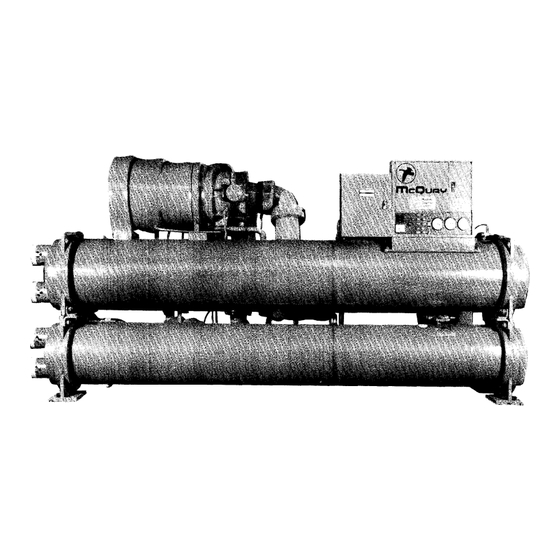
INSTALLATION 1. CEO63 Compressors 7. Oil Level Sight Glass 13. Condenser Inlet 2. Lube Boxes 8. Hot Gas Bypass 14. Condenser Outlet 3. Suction Shutoff Valve 9. Oil Coolers 15. Evaporator Inlet 4. Condenser Relief Valves 10. Discharge Check Valve 16. -
Page 8: Thermal Insulation
Care should be taken not to tear, damage or remove any of this factory insulation. parts of the Templifier unit as needed to prevent sweating, to retain thermal efficiency, and to protect All field piping connections to the Templifier should be operating personnel from hot surfaces. -
Page 9: Testing Control Circuit
TESTING CONTROL CIRCUIT age drop should be physically measured. The installing contractor should complete all field connections to the Templifier control panel after which Control Interlocks he should check out all remote interlocks for proper Water flow interlock terminals are provided on the operation. - Page 10 INSTALLATION 1. CE126 Compressor 7. Evaporator Oil Level Sight Glass 2. Motor Terminal Cover 8. Condenser Oil Sump 3. Lube Box 9. Control Center Oil Cooler Water Lines 4. Oil Coolers 10. Discharge Check Valve Motor Liquid Cooling Line 5. Expansion Valves 11.
- Page 11 Charging the System ment estimated for the unit can be charged in this manner. All Templifier Heat Pumps are leak tested at the factory and shipped with the operating charge of After 75% of the required charge has entered the refrigerant as indicated on the unit nameplate.
Need help?
Do you have a question about the Templifier and is the answer not in the manual?
Questions and answers