Advertisement

LAUNCH

Table of Contents

..........................................
2.1 Structural Diagram......................................2
2.2 Working Principle........................................4
...........................................
..........................................
5.1 Precautions for Installation........................6
5.2 Installation Procedures...............................6
5.2.1 Overall Positioning..................................6
5.2.2 Base Plate Layout....................................7
www.diagtools.eu, Pernavas 43A, Riga, Latvia, LV-1009, +37129416069, info@diagtools.eu
440(440W) 455(455W) Installation Manual
5.2.8 Air line connection...................................15
1
5.2.9Anchoring the columns ... ........................16
...
2
ramps.........................................................17
.........
6
plates...........................................................17
6
5.2.12 Rolling jack installation...........................17
6
6 Adjustment..............................................18
6.1 Preparation.............................................18
6.2 Adjustment Procedures.............................18
Hydraulic Diagram......................................28
Pneumatic Diagram................................. 29
i
...........................................
.................................
19
30

Advertisement

Table of Contents
loading

Summary of Contents for Launch TLT440

  • Page 1: Table Of Contents

    LAUNCH 440(440W) 455(455W) Installation Manual 5.2.7 Install the Power Unit, hydraulic lines………13 Table of Contents 5.2.8 Air line connection……………………………..15 …………………………………… 1 Precautions 5.2.9Anchoring the columns … ……………………16 … 2 Overall Structure and Working Principles 5.2.10 Installation of wheel stop Plates and Drive on 2.1 Structural Diagram………………………………..2...
  • Page 2: Precautions

    Keep it away from heating device, faucet, other than the designed purpose. humidifier or furnace. l Check the components against parts list before installation. In case of any questions, please contact your dealer or Launch Tech www.diagtools.eu, Pernavas 43A, Riga, Latvia, LV-1009, +37129416069, info@diagtools.eu...
  • Page 3: Overall Structure And Working Principles

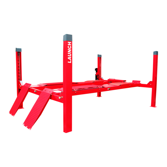
    Front Cross Tube Power Unit Left Runway Right Runway Cables RL Column RR Column Rear Cross Tube Drive On Ramp 500(550) 950(1000) 500(550) 3445 Fig.1 (TLT440,TLT455) The structural diagram of TWA440W alignme www.diagtools.eu, Pernavas 43A, Riga, Latvia, LV-1009, +37129416069, info@diagtools.eu...
  • Page 4 LAUNCH 440(440W) 455(455W) Installation Manual FL C olumn FR C olumn Pow er Un it Ai r Lub ricato r Oil H ose Fr ont C ross Tube C ontro l Air Valve Wh eel S top Fron t Cov er...
  • Page 5: Working Principle

    LAUNCH 440(440W) 455(455W) Installation Manual 2.2 Working Principle from falling. For lowering the lift, when the Lifting mechanism: The hydraulic cylinder is locking latches rest on the plates, it must be located below the cylinder runway. When the raised enough for all 4 latches to clear the latch hydraulic oil enters the front cavity of the cylinder, plates slots inside the columns.
  • Page 6 LAUNCH 440(440W) 455(455W) Installation Manual Safety mechanism L o c k i n g l at c h p l a t e S l a c k c abl e d e v i c e L oc k i n g l a t c h...
  • Page 7: Tools For Installation And Adjustment

    LAUNCH 440(440W) 455(455W) Installation Manual a new horizontal concrete slab if possible. Don’t expect to 3 Tools for installation and compensate for the serious slope by shimming. Don’t install the lift on any asphalt surface or any surface adjustment other than concrete. The lift must be installed on concrete...
  • Page 8: Base Plate Layout

    LAUNCH 440(440W) 455(455W) Installation Manual ≥ 1 m Fig.5 5.2.2 Base Plate layout Note: The bay layout is shown in Fig. 6. All the dimensions are based on the external With total width as the basis, draw two parallel lines (#1 border of the base plate.
  • Page 9 LAUNCH 440(440W) 455(455W) Installation Manual 1 # F ro nt Lef t Col um n 2# Fr on t R ig ht Co lum n 2 68 3# Re ar Le ft Co lu mn 4# Rea r Rig ht Co lu mn...
  • Page 10: Runway And Cross Tube Installation

    LAUNCH 440(440W) 455(455W) Installation Manual not assemble the sheaves in the cross tube 5.2.3 Runway and cross tube installation ends at this time. Be sure cables are not Position left runway in bay with hydraulic crossed inside tube. cylinder connection to front of bay. Cable and With the openings in the cross tube side lined up sheaves are pre-assembled in runway.
  • Page 11: Position Columns And Locking Latch Plates

    LAUNCH 440(440W) 455(455W) Installation Manual 前梁 后 梁 Fig.8 back of the column (Fig.4). The latch plate should be 5.2.4 Position columns and locking latch plates oriented toward the back of the column from the centre Place the power unit column at the FL (front left) corner line of the threaded stud.
  • Page 12: Column And Cross Tube Assembly

    LAUNCH 440(440W) 455(455W) Installation Manual 5.2.5 Column and cross tube assembly Bolt sliders onto each side of the cross tube ends. plate should engage the sliders for at least 1” when When both sliders are attached, push column toward the lift is completely lowered. Repeat this procedure cross tube end until sliders touch latch plate.( Fig.10...
  • Page 13 LAUNCH 440(440W) 455(455W) Installation Manual Sheave Cylinder Cable II CableI 2-M20 Nut M20 Nut φ20 Washer Cable III Cable IV Fig.12 crossing or improper installation before running Cautions: the lift. Make sure the cables are placed in the Adjust the 4 cables for equal tension.
  • Page 14: Install The Power Unit, Hydraulic Lines

    LAUNCH 440(440W) 455(455W) Installation Manual that no leakage will occur.(Fig.14) 5.2.7 Install the Power Unit, hydraulic lines Fill the tank with enough hydraulic oil (10L). Keep Install the hydraulic unit on the bracket with 2 M10X25 dust and other pollutants away from the oil tank bolts and washers (Fig.13B).
  • Page 15 LAUNCH 440(440W) 455(455W) Installation Manual Front Left Colum n Air Con tro l Va lve Powe r Uni t A ir Hose Air Contro l Val ve Oil H ose Air V alve B racke t Air C onnec tor...
  • Page 16: Air Line Connection

    LAUNCH 440(440W) 455(455W) Installation Manual 5.2.8 Air line connection Locking latches require 100 psi. min to 120 psi. max leaks by depressing air valve. Actuate air control valve air pressure. A filter/regulator/lubricator must be and check latch operation on all four corners. The installed on air supply at lift.
  • Page 17: 9Anchoring The Columns

    LAUNCH 440(440W) 455(455W) Installation Manual and fastening the bolts, make sure the column is 5.2.9 Anchoring the columns not moved. (Fig. 16) Align the columns with the base and keep it Adjust the bolt M20 of on top plate of the column upright on the floor.
  • Page 18: Installation Of Wheel Stop Plates And Drive On

    LAUNCH 440(440W) 455(455W) Installation Manual 5.2.10 Installation of wheel stop Plates and perpendicular. Drive-on Ramps Let the drill work itself. Don’t apply the extra force, Install wheel stop plates and drive-on ramp (Fig. 2). and don’t ream the hole or allow the drill to wobble.
  • Page 19: Adjustment

    LAUNCH 440(440W) 455(455W) Installation Manual latches to clear the latch plate slots inside the columns. 6. Adjustment Actuate the air control valve to disengage all the 4 locking plates and push the lowering handle on the power unit to lower the lift.
  • Page 20: Parts List

    LAUNCH 440(440W) 455(455W) Installation Manual You may order new spare parts to replace damaged ones 7 Parts List according to their material codes in the list. This parts list is only for the service and maintenance. www.diagtools.eu, Pernavas 43A, Riga, Latvia, LV-1009, +37129416069, info@diagtools.eu...
  • Page 21 LAUNCH 440(440W) 455(455W) Installation Manual Material code Name 201020712 FL column 201020698 Locking latch plate assembly 103030114 Hexagon nut C class M20 GB41-86 Washer C class 20 GB95-85 103040138 103030143 Thin nut A,B class M20 GB6172-86 Quick L type air fitting APL8-02(for FRL 103100080 UNIT)...
  • Page 22 LAUNCH 440(440W) 455(455W) Installation Manual www.diagtools.eu, Pernavas 43A, Riga, Latvia, LV-1009, +37129416069, info@diagtools.eu...
  • Page 23 LAUNCH 440(440W) 455(455W) Installation Manual Material code Name 201020703 440 Front cross tube assembly 201021126 455 Front cross tube assembly 201020697 440 Rear cross tube assembly 201021126 455 Rear cross tube assembly 103020132 Screw M8*15 GB/T5789-86 201020696 440 Sheave pin assembly...
  • Page 24 LAUNCH 440(440W) 455(455W) Installation Manual 3 0 4 3 0 3 3 0 5 3 0 6 3 0 7 3 0 1 3 0 2 3 0 8 3 0 9 3 1 0 3 1 1 3 1 3...
  • Page 25 LAUNCH 440(440W) 455(455W) Installation Manual Material code Name 104130231 Thin rubber pad 103201482 Cover assembly 104130232 Thick rubber pad 103201486 Left hand sliding adapter 103201488 Telescoping end welding seat 103050002 Returning ring 12 104990116 roller 103201495 axle 104990115 Outer arm slider...
  • Page 26 LAUNCH 440(440W) 455(455W) Installation Manual TLT440,TLT455 www.diagtools.eu, Pernavas 43A, Riga, Latvia, LV-1009, +37129416069, info@diagtools.eu...
  • Page 27 LAUNCH 440(440W) 455(455W) Installation Manual 4 02 4 03 40 1 40 5 4 06 4 0 7 4 0 8 40 9 4 1 0 41 1 41 2 41 3 4 3 0 41 4 4 15 41 6...
  • Page 28 LAUNCH 440(440W) 455(455W) Installation Manual Material code Name 201011348 Front wheel stop 103020073 Screw M10*20 GB/T5789-86 201020692 Short up cover 103201518 Turn table 201020713 440 Left runway 201021127 455 left runway 103201981 440 left Sheave 104990137 455 sheave 104990121 440 Spacer...
  • Page 29: Hydraulic Diagram

    LAUNCH 440(440W) 455(455W) Installation Manual 103201507 Drive on ramp bar 201020706 Drive ramp 201020691 Side slip plate assembly 104080008 Ball seat 104080007 Ball 201020694 Cover of side slip plate 201020690 Fixing pin Diagram of hydraulic system: 1.Gear Pump 2.Motor 3.Filter 4.Check-Valve 5.Safety Valve 6.Release Valve 7.Flow Control Valve...
  • Page 30: Pneumatic Diagram

    3 . Ai r Cy l in d er 4 P ne um a tic Pum p 5 C yl ind e r TLT440, TLT455 Diagram of Pneumatic system: 1.Air Source 2. Air Control Valve 3. Air Cylinder www.diagtools.eu, Pernavas 43A, Riga, Latvia, LV-1009, +37129416069, info@diagtools.eu...
  • Page 31: Electrical Diagram

    LAUNCH 440(440W) 455(455W) Installation Manual Diagram of electrical system: KM Contactor 380V ~ www.diagtools.eu, Pernavas 43A, Riga, Latvia, LV-1009, +37129416069, info@diagtools.eu...

This manual is also suitable for:

Tlt455Tlt440wTlt455w

Table of Contents