Table of Contents
Advertisement
Quick Links
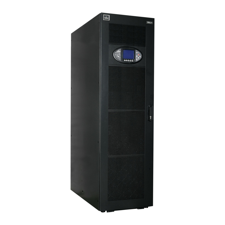
Liebert APM 150 Integrated UPS Single Module And Parallel System
User Manual
Version
V1.6
Revision date
March 10, 2017
BOM
31012429
Emerson Network Power provides customers with technical support. Users may contact the nearest
Emerson local sales office or service center.
Copyright © 2011 by Emerson Network Power Co., Ltd.
All rights reserved. The contents in this document are subject to change without notice.
Emerson Network Power Co., Ltd.
Address: Block B2, Nanshan I Park, No.1001 Xueyuan Road, Nanshan District, Shenzhen, 518055, P.R.China
Homepage: www.emersonnetworkpower.com
E-mail: overseas.support@emerson.com
Advertisement
Table of Contents

Related Manuals for Liebert APM 150


Summary of Contents for Liebert APM 150
- Page 1 Liebert APM 150 Integrated UPS Single Module And Parallel System User Manual Version V1.6 Revision date March 10, 2017 31012429 Emerson Network Power provides customers with technical support. Users may contact the nearest Emerson local sales office or service center.
- Page 2 Special Declaration Personnel Safety 1. This product must be installed and commissioned by professional engineers of the manufacturer or its authorized agent. Failure to observe this could result in product malfunction or personnel safety risk. 2. Take the time to read this product manual and the safety precaution thoroughly before installing and commissioning this product.
- Page 3 Used to advise the user to carefully read and observe this unit though it may not cause damage. This manual contains information concerning the installation and operation of this Emerson Liebert APM 150 Integrated UPS Single Module And Parallel System (UPS for short).
- Page 4 Warning: backfeed protection This UPS is fitted with a voltage-free contact closure signal for use with an external automatic disconnect device (supplied by others) to protect against back-feeding voltage into the static bypass input. If this signal is not used by the installer, a label must be added at the external bypass input disconnect device to warn service personnel that the circuit is connected to a UPS.
- Page 5 This Manual Describes The Following UPS Product Product Model 150kVA Liebert APM 150...
- Page 6 Add a Warning in Safety Precautions; update Table 11-3. V1.6 (March 10, 2017) Change ' ' to ' ' in Table 8-1; update Appendix 2; Change user manual name to 'Liebert UF-DRY310 UF-DRY410 APM 150 Integrated UPS Single Module And Parallel System'.
-
Page 7: Table Of Contents
Contents Chapter 1 Overview ..............................1 1.1 Features................................. 1 1.2 Design Concept .............................. 1 1.2.1 System Design ............................. 1 1.2.2 Bypass ..............................2 1.2.3 System Control Principle ........................3 1.2.4 UPS Power Supply Switch Configuration ....................4 1.2.5 BCB ..............................4 1.3 Parallel System ............................... - Page 8 3.1.8 Power Cable Connection Procedures .....................19 3.2 Wiring Of Signal Cable ...........................22 3.2.1 Overview ............................22 3.2.2 Input Dry Contact Port .........................23 3.2.3 BCB Port .............................23 3.2.4 Maintenance Switch And Output Switch State Port .................24 3.2.5 Output Dry Contact Port ........................24 3.2.6 Remote EPO Input Port ........................25 3.2.7 RS485 Port, RS232 Port And Intellislot Port ....................25 Chapter 4 Operator Control And Display Panel ......................27...
- Page 9 5.10 Automatic Restart ............................45 5.11 Selecting Language .............................45 5.12 Changing The Current Date And Time ......................45 5.13 Command Password ............................46 Chapter 6 Battery ..............................47 6.1 Introduction..............................47 6.2 Safety ................................47 6.3 UPS Battery ..............................48 6.4 Precautions For Installation Design ........................49 6.5 Battery Installation Environment And Number Of Batteries ................49 6.5.1 Installation Environment: ........................49 6.5.2 Number Of Batteries ..........................50 6.6 Battery Protection ............................50...
- Page 10 Chapter 8 Option ...............................64 8.1 Option List ..............................64 8.2 Option ................................65 8.2.1 Battery Temperature Sensor .........................65 8.2.2 Parallel Cable ............................65 8.2.3 LBS Cable ............................65 8.2.4 SIC Card ..............................65 8.2.5 Relay Card............................66 8.2.6 Modbus Card ............................69 8.2.7 UF-RS485 Card ............................69 8.2.8 LBS Adapter ............................70 8.2.9 SiteMonitor Monitoring Software ......................73 8.2.10 SPM Monitoring Module ........................73 8.2.11 Basic Unit For Common Distribution ....................73...
- Page 11 11.8 Efficiency, Heat Losses And Air Exchange ......................83 Appendix 1 Glossary ..............................84 Appendix 2 Hazardous Substances And Content .......................85...
-
Page 12: Chapter 1 Overview
Chapter 1 Overview This chapter introduces the features, design concept, parallel system, operation mode, battery management and battery protection of Liebert APM 150 Integrated UPS Single Module And Parallel System (UPS for short). 1.1 Features The UPS is connected between the three-phase input power and the critical loads (e.g. computer) to provide high quality three-phase power for the loads. -
Page 13: Bypass
(no-break) load transfer between the inverter output and static bypass line. The synchronization between the inverter output and static bypass is achieved through the inverter control Liebert APM 150 Integrated UPS Single Module And Parallel System User Manual... -
Page 14: System Control Principle
The transfer is determined first of all by the features of the protection device of the system. In the above two situations, the UPS operation control panel will display alarm message. Liebert APM 150 Integrated UPS Single Module And Parallel System User Manual... -
Page 15: Ups Power Supply Switch Configuration
As shown in Figure 1-3, two UPS modules can be parallel-connected to form a parallel system to increase the system capacity or reliability, or both. The load is equally shared between the paralleled UPSs. Liebert APM 150 Integrated UPS Single Module And Parallel System User Manual... -
Page 16: Parallel System Features
3. The outputs of the two UPS modules must be connected to a common output bus. 1.4 Operation Mode The UPS is an on-line, double-conversion, reverse-transfer UPS that permits operation in these modes: Normal mode Battery mode Liebert APM 150 Integrated UPS Single Module And Parallel System User Manual... - Page 17 Should the inverters be asynchronous with the bypass, the static switch will perform a transfer of the load from the inverters to the bypass, with interruption in power to the load. This is to avoid Liebert APM 150 Integrated UPS Single Module And Parallel System User Manual...
- Page 18 Inverter LED is normally off, and the corresponding alarm message 'Bypass mode' will appear on the LCD. Liebert APM 150 Integrated UPS Single Module And Parallel System User Manual...
- Page 19 For single input load, an optional STS can be installed to power the load. For the operation principle diagram of the dual bus system mode, see Figure 7-7. Liebert APM 150 Integrated UPS Single Module And Parallel System User Manual...
-
Page 20: Battery Management
The time can be configured from 3min to 60min. EOD protection When the battery voltage drops to the EOD voltage, the battery converter shuts down. The EOD voltage is adjustable from 1.6V/cell to 1.75V/cell (VRLA). Liebert APM 150 Integrated UPS Single Module And Parallel System User Manual... - Page 21 This warning occurs when the BCB opens. The battery is connected to the UPS through the BCB, which is manually closed and electronically tripped by the UPS control circuits. Liebert APM 150 Integrated UPS Single Module And Parallel System User Manual...
-
Page 22: Chapter 2 Mechanical Installation
3. Verify that the correct UPS is being installed. The UPS has an identification tag on the back of the front door reporting the model, capacity and parameters of the UPS. Liebert APM 150 Integrated UPS Single Module And Parallel System User Manual... -
Page 23: Environmental Requirement
During storage, periodically charge the battery according to the battery manufacturer instructions. In the charge process, temporarily connect the UPS to the mains for the time required for recharging the battery to activate the battery. Liebert APM 150 Integrated UPS Single Module And Parallel System User Manual... -
Page 24: Mechanical Requirement
Switch unit Standard component Bypass module Standard component 1 ~ 5 1 ~ 5 1 ~ 5 Power module Requisite. Installed at site Liebert APM 150 Integrated UPS Single Module And Parallel System User Manual... -
Page 25: Moving The Cabinet
Figure 2-1 is used to install an output distribution module. Install the power modules and output distribution modules from bottom to top to avoid cabinet toppling due to high gravity center. Liebert APM 150 Integrated UPS Single Module And Parallel System User Manual... - Page 26 2. Insert the output distribution module in the installation position, and push it into the cabinet. 3. Secure the module to the cabinet through the fixing holes on both sides of the front panel of the module. Liebert APM 150 Integrated UPS Single Module And Parallel System User Manual...
-
Page 27: Installation Diagram
Back door Back door Bottom view Bottom view Top view (front and back doors open) Top view (front and back doors open) Figure 2-3 UPS installation dimensions (unit: mm) Liebert APM 150 Integrated UPS Single Module And Parallel System User Manual... -
Page 28: Chapter 3 Electrical Installation
, Output current at full load (36 Battery discharge current at (kVA) cells) battery recharge 380V 400V 415V 380V 400V 415V 1. Rectifier and bypass input mains current. Liebert APM 150 Integrated UPS Single Module And Parallel System User Manual... -
Page 29: Minimum Distance From Floor To Ups Connection Point
Overcurrent protection must be installed at the distribution panel of the incoming main supply. The protection must discriminate with the power cable current capacity and with the overload capacity of the Liebert APM 150 Integrated UPS Single Module And Parallel System User Manual... -
Page 30: Power Cable Connection Procedures
2. Open the back door of the UPS cabinet and remove the protective cover to gain access to the input terminals, battery terminals and PE terminals, as shown in Figure 3-2. Liebert APM 150 Integrated UPS Single Module And Parallel System User Manual... - Page 31 If output distribution modules are configured, connect the L cables, N cables and PE cables between the output terminals of the output distribution modules and the load according to Figure 3-3. Tighten the bolts (M6) to 5Nm. Ensure correct phase rotation. Liebert APM 150 Integrated UPS Single Module And Parallel System User Manual...
- Page 32 Chapter 3 Electrical Installation Liebert APM 150 Integrated UPS Single Module And Parallel System User Manual...
-
Page 33: Wiring Of Signal Cable
For maximum run between 20m and 30m, the typical CSA should be from 0.5mm to 1.5mm Liebert APM 150 Integrated UPS Single Module And Parallel System User Manual... -
Page 34: Input Dry Contact Port
BCB online - input (normally open): This pin will become active when the BCB port is J6.4 connected The connection between the BCB port and the BCB is shown in Figure 3-9. Liebert APM 150 Integrated UPS Single Module And Parallel System User Manual... -
Page 35: Maintenance Switch And Output Switch State Port
Figure 3-11 and described in Table 3-6. The shunt trip coil of the external air breaker can be driven directly through this dry contact. The shunt trip coil of the external air breaker should be 250Vac/5A or 24Vdc/5A. Figure 3-11 Output dry contact port Liebert APM 150 Integrated UPS Single Module And Parallel System User Manual... -
Page 36: Remote Epo Input Port
The three Intellislot ports are used to install optional communication cards at site, including relay card, Modbus card, SIC card and UF-RS485 card. For details, refer to Chapter 8 Option. Liebert APM 150 Integrated UPS Single Module And Parallel System User Manual... - Page 37 2. Intellislot 2 port shares communication resource with the SPM monitoring module. If the SPM monitoring module is configured, optional communication cards cannot be installed in Intellislot 2 port. Liebert APM 150 Integrated UPS Single Module And Parallel System User Manual...
-
Page 38: Chapter 4 Operator Control And Display Panel
INVERTER OFF Inverter shutdown switch Inverter indicator FAULT CLEAR Fault reset switch Load indicator SILENCE ON/OFF Audible alarm silencing switch F1 ~ F5 Status indicator LCD menu keys Liebert APM 150 Integrated UPS Single Module And Parallel System User Manual... -
Page 39: Led Indicators
Restart the UPS (subject to any fault being cleared) Audible alarm silencing SILENCE When an alarm is active, pressing this button silences the audible alarm. switch ON/OFF Pressing this button again enables the buzzer again Liebert APM 150 Integrated UPS Single Module And Parallel System User Manual... -
Page 40: Lcd And Menu Keys
After the UPS starts and finishes self-test, the primary screen appears, as shown in Figure 4-3. The primary screen is divided into four windows: system information window, menu window, data window and keypad window. Liebert APM 150 Integrated UPS Single Module And Parallel System User Manual... -
Page 41: Default Screen
During UPS operation, if there is no alarm within two minutes, the default screen will appear, as shown in Figure 4-5. After a short delay, the LCD backlight will turn off. Pressing any keys (F1 ~ F5) restores the default screen. Liebert APM 150 Integrated UPS Single Module And Parallel System User Manual... -
Page 42: Detailed Description Of Menu Items
L-L voltage (V) Line voltage L-N voltage (V) Phase voltage L-N current (A) Phase current Output Frequency (Hz) Output frequency L-L voltage (V) Line voltage Power factor Power factor Liebert APM 150 Integrated UPS Single Module And Parallel System User Manual... - Page 43 Displays the alarm history. For the list of the alarms that may be Records (alarm history) displayed on the LCD on the UPS operator control and display panel, refer to Table 4-9 Language (language option) Provides two optional LCD languages Liebert APM 150 Integrated UPS Single Module And Parallel System User Manual...
- Page 44 Provides the SPM DSP software version Keypad window The functions of the menu keys F1 ~ F5 for the current screen are shown by self-explanatory icons on the keypad window as appropriate. Liebert APM 150 Integrated UPS Single Module And Parallel System User Manual...
-
Page 45: Prompt Window
The mains frequency is outside specifications and results in rectifier shutdown. Check Mains Freq. Abnormal the rectifier input voltage and frequency Batt. Charger Fail The voltage of the battery charger is too high Liebert APM 150 Integrated UPS Single Module And Parallel System User Manual... - Page 46 Control power 1 fail The UPS is operating but the redundant control power is abnormal or not available Liebert APM 150 Integrated UPS Single Module And Parallel System User Manual...
- Page 47 The LBS setting is active. The UPS is acting as an LBS master or slave in a dual bus LBS Active configuration Mains Neutral Lost The neutral line of the AC input mains is not detected Liebert APM 150 Integrated UPS Single Module And Parallel System User Manual...
- Page 48 Emerson Data check error of acquisition arithmetic module. Seek technical assistance from the SPM CRC Check Error local customer service center of Emerson Liebert APM 150 Integrated UPS Single Module And Parallel System User Manual...
- Page 49 If the alarms are caused by the values set by the Emerson-authorized commissioning engineer using the configuration software, and the user need to change the setting values, please contact the local customer service center of Emerson. Liebert APM 150 Integrated UPS Single Module And Parallel System User Manual...
-
Page 50: Chapter 5 Operating Instructions
Output distribution switch Output distribution switch Output distribution switch Input switch Output switch Output switch Input switch Maintenance switch (locked) Maintenance switch (locked) Figure 5-1 Positions of power switches Liebert APM 150 Integrated UPS Single Module And Parallel System User Manual... -
Page 51: Ups Start-Up Procedures
The UPS begins to operate in normal mode, and the states of the indicators are as shown in Table 5-2. Table 5-2 Indicator state Indicator State Rectifier indicator Green Battery indicator Bypass indicator Inverter indicator Green Load indicator Green Status indicator Green Liebert APM 150 Integrated UPS Single Module And Parallel System User Manual... -
Page 52: Start-Up Procedures (Into Battery Mode, Battery Cold Start)
Before performing this operation, read the messages on the LCD to be sure that bypass supply is normal and the inverters are synchronous with it. If these conditions are not present, there is a risk of a short interruption in powering the load. Liebert APM 150 Integrated UPS Single Module And Parallel System User Manual... -
Page 53: Transfer From Maintenance Mode To Normal Mode
The manual maintenance test is initiated through the LCD menu on the operator control and display panel, and it requires password verification. The procedures for the manual maintenance test are as follows: Liebert APM 150 Integrated UPS Single Module And Parallel System User Manual... -
Page 54: Battery Capacity Test Procedures
Five seconds later, if all indicators illuminate green constantly, and then turns constant red, it indicates that all indicators are normal. 4. Stop the test. During system test, you can stop it be selecting the Stop testing option on the Command menu. Liebert APM 150 Integrated UPS Single Module And Parallel System User Manual... -
Page 55: Ups Shutdown Procedures
If the mains input is present, the UPS control circuit will remain active; however, the output will be turned off. To remove all power from the UPS, the UPS input switch should be opened. Liebert APM 150 Integrated UPS Single Module And Parallel System User Manual... -
Page 56: Ups Reset Procedures
1. From the OutPut menu, press the F3 or F4 (left or right) key as needed to select the Settings menu. 2. Press the F5 (enter) key to move the cursor to the data window on the screen. Liebert APM 150 Integrated UPS Single Module And Parallel System User Manual... -
Page 57: Command Password
6. Press the F5 (enter) key to save the settings, then press the F2 (ESC) key to return to the OutPut menu. 5.13 Command Password Password protection is used to limit the control functions accessible to the operator. This password provides access to UPS and battery test functions. Liebert APM 150 Integrated UPS Single Module And Parallel System User Manual... -
Page 58: Chapter 6 Battery
The requirements on torque specified in the instructions or user manual provided by the battery manufacturer shall be satisfied. All connections between the terminals and the batteries shall Liebert APM 150 Integrated UPS Single Module And Parallel System User Manual... -
Page 59: Ups Battery
Otherwise, the battery inconsistency will cause frequent over-discharge or under-charge of certain battery. At last, the battery will have premature failure, and the entire string of battery will have insufficient backup time. Liebert APM 150 Integrated UPS Single Module And Parallel System User Manual... -
Page 60: Precautions For Installation Design
Igas - The gas evolving current density under battery float charging or equalizing charge conditions, the unit is mA/Ah Igas=1, under the float charging condition of 2.27V/cell Igas=8, under the equalizing charge condition of 2.35V/cell Crt - 20hr battery rated capacity Liebert APM 150 Integrated UPS Single Module And Parallel System User Manual... -
Page 61: Number Of Batteries
UPS shall be minimized. The BCB should provide: Overcurrent protection Short circuit protection Automatic tripping function Liebert APM 150 Integrated UPS Single Module And Parallel System User Manual... -
Page 62: Battery Installation And Connection
6. After cable connection, it is prohibited to pull the battery cables or the cable terminals. 7. Do not cross the battery cables during connection, and do not tie the battery cables together. 8. Refer to Figure 6-1 for the battery cable connection. Liebert APM 150 Integrated UPS Single Module And Parallel System User Manual... -
Page 63: Battery Room Design
With this function, we can adjust the float charging voltage of the battery to make it inversely proportional to the ambient temperature of the battery cabinet/chamber, so as to prevent the over-charge of the battery under high ambient temperature. Liebert APM 150 Integrated UPS Single Module And Parallel System User Manual... -
Page 64: Reference Current And Connection Of Bcb
3. The max. battery neutral cable current can reach half of the current of the battery positive and negative cables. When sizing the neutral cable, refer to this cable, and take the neutral cable currents as half of the currents listed in the table. Liebert APM 150 Integrated UPS Single Module And Parallel System User Manual... - Page 65 If you select the BCB box (containing a BCB and a BCB control board) made by Emerson, you need to modify the BCB box and connect the BCB box with the battery and UPS according to Figure 6-6. Liebert APM 150 Integrated UPS Single Module And Parallel System User Manual...
-
Page 66: Battery Maintenance
Random discard or any other improper disposal of the disused lead-acid storage battery may cause severe environment pollution and the relevant person will be investigated of corresponding legal responsibilities. Liebert APM 150 Integrated UPS Single Module And Parallel System User Manual... -
Page 67: Chapter 7 Parallel System & Dual Bus System
Position the UPS modules and make connection as shown in Figure 7-1. The output distribution mode (where Q1EXT and Q2EXT must be fitted) shown in Figure 7-1 is recommended to facilitate maintenance and system testing. Liebert APM 150 Integrated UPS Single Module And Parallel System User Manual... -
Page 68: External Protective Device
Figure 7-2; connect these four copper bars respectively to the four terminals (A, B, C, N) of the maintenance switch in the front of cabinet, which serve as output terminals, as shown in Figure 7-3. Liebert APM 150 Integrated UPS Single Module And Parallel System User Manual... -
Page 69: Parallel Cable
You must use the shortest parallel cables to suit the application and must not coil excess. Meanwhile, separate the parallel cables from the power cables to prevent electrical interferences. Liebert APM 150 Integrated UPS Single Module And Parallel System User Manual... -
Page 70: Remote Epo
Bypass module Bypass module J10: 3 J10:3 J10: 4 J10:4 J10:3 J10: 3 J10: 4 J10:4 Bypass module Bypass module UPS 1 UPS1 Figure 7-6 EPO circuit diagram Liebert APM 150 Integrated UPS Single Module And Parallel System User Manual... -
Page 71: Operating Procedures Of Parallel System
1. Close the output switch of the UPS to be re-integrated. 2. Close the input switch and BCB of the UPS. 3. Press and hold the INVERTER ON button of the UPS for 2s. Liebert APM 150 Integrated UPS Single Module And Parallel System User Manual... -
Page 72: Shutdown Procedures (Completely Powering Down The Ups)
This procedure is applicable for completely powering down the UPS and still keeping the power supply to the load. Refer to 5.7.2 Completely Powering Down The UPS Whilst Maintaining The Power Supply To The Load for the operating procedures. Liebert APM 150 Integrated UPS Single Module And Parallel System User Manual... -
Page 73: Installation Of Dual Bus System
You must use the shortest LBS cable to suit the application and must not coil excess. Meanwhile, separate the LBS cable from the power cables to prevent electrical inteferences. Liebert APM 150 Integrated UPS Single Module And Parallel System User Manual... - Page 74 UPS 2 UPS 1 Bypass module Bypass module Bypass module Bypass module Figure 7-10 Connection of typical dual bus system of two single UPSs with redundancy LBS cable Liebert APM 150 Integrated UPS Single Module And Parallel System User Manual...
-
Page 75: Chapter 8 Option
2. Intellislot 2 port shares communication resource with the SPM monitoring module. If the SPM monitoring module is configured, optional communication cards cannot be installed in Intellislot 2 port. Liebert APM 150 Integrated UPS Single Module And Parallel System User Manual... -
Page 76: Battery Temperature Sensor
The SIC card is a network management card. It can make the UPS made by Emerson real network equipment. It can also be connected to the IRM series sensor to provide environment monitoring function. When the Liebert APM 150 Integrated UPS Single Module And Parallel System User Manual... -
Page 77: Relay Card
K3_COM, Channel 3 dry contact common output contact K3_NC, Channel 3 dry contact normally closed output Pin 7 Open: UPS Faulty contact Pin 24 DRY_IN2, Channel 2 dry contact signal input Reserved Liebert APM 150 Integrated UPS Single Module And Parallel System User Manual... - Page 78 Figure 8-3 ~ Figure 8-5 show the appearance and wiring principle of each cable. Figure 8-3 Appearance and wiring schematic of cable 1 (UFDRY21SL1) Figure 8-4 Appearance and wiring schematic of cable 2 (UFDRY21SL2) Liebert APM 150 Integrated UPS Single Module And Parallel System User Manual...
- Page 79 The relay card is hot-pluggable, you can install it without shutting down the UPS. a) Remove the Intellislot port cover on the front panel of the control module on the top of the UPS bypass cabinet. Save the screws. Liebert APM 150 Integrated UPS Single Module And Parallel System User Manual...
-
Page 80: Modbus Card
The goldfinger is used for insertion into the Intellislot port of the UPS. It provides RS232 input signal. The RJ45 port 1 and RJ45 port 2 are in parallel connection. They provide RS485 output signal. Liebert APM 150 Integrated UPS Single Module And Parallel System User Manual... -
Page 81: Lbs Adapter
The LBS adapter is designed to extend the LBS function up to 150m between the two UPS modules or systems of a dual bus system. The adapter also enables an APM 150 UPS to synchronize with other UPS models Appearance The appearance of the LBS adapter is shown in Figure 8-8. - Page 82 Yellow LED. On: The LBS adapter is connected to a non-APM 150 UPS; off: The LBS adapter is connected to an APM 150 UPS The switch should be placed to right if the LBS adapter is connected to an APM 150 UPS; it should SWITCH...
- Page 83 2) Connect the end of the LBS cable with a DB9 port to COM1 port of the LBS adapter, and connect the other end of the LBS cable with an RJ45 port to the J4 port of the bypass module of the APM 150 UPS. Make no connection to the COM1 port of the LBS adapter connected to the non-APM 150 UPS.
-
Page 84: Sitemonitor Monitoring Software
The maximum configuration number of the former two types is three, and that of the latter two is four. The intelligent MCB distribution module and intelligent hot-pluggable MCB distribution module are used with the SPM monitoring module to achieve intelligent power distribution and management function. Liebert APM 150 Integrated UPS Single Module And Parallel System User Manual... - Page 85 In addition, the MCB configurations provided in Table 8-7 are also available for users' selection. Table 8-7 MCB configuration (optional) Switch capacity Pole number of switch Switch quantity (pcs) 10A, 16A, 25A Liebert APM 150 Integrated UPS Single Module And Parallel System User Manual...
-
Page 86: Chapter 9 Communication
EPO. These functions are realized through the following interfaces on the external interface board (EIB): Input dry contact port Output dry contact port EPO input port Liebert APM 150 Integrated UPS Single Module And Parallel System User Manual... -
Page 87: Chapter 10 Service And Maintenance
To ensure the safety and stability of the UPS system, the user must replace the electrolytic capacitors by the end of their service life. It is recommended to replace the electrolytic capacitors after five to six years in service. Liebert APM 150 Integrated UPS Single Module And Parallel System User Manual... -
Page 88: Ac Capacitor
3. Remove the air filter, and insert a clean one. 4. Replace the fixing bar. Fixing bar Fixing bar Fixing bar Fixing bar Air filters Air filters Air filters Air filters Figure 10-1 Replacing air filter Liebert APM 150 Integrated UPS Single Module And Parallel System User Manual... -
Page 89: The Maintenance Of Ups And Options
The module will be blocked by a spring piece on the left side of the module when the module is pulled out of the cabinet halfway. At this point, you must press the spring piece before you continue to pull the module out. Liebert APM 150 Integrated UPS Single Module And Parallel System User Manual... -
Page 90: Service Procedures Of Bypass Module
4. After servicing the module, verify that all output distribution switches of this module are open. 5. Insert the module into the cabinet, and tighten the screws on both sides. 6. Connect the cables back to the output terminals of this module. Liebert APM 150 Integrated UPS Single Module And Parallel System User Manual... -
Page 91: Chapter 11 Specifications
120 (with redundant power module) Dimensions (W × D × H) 600 ×1100×2000 Weight (excluding battery) Color Black ZP7021 Protection degree, IEC (60529) IP20 (front door open or closed, back door closed) Liebert APM 150 Integrated UPS Single Module And Parallel System User Manual... -
Page 92: Electrical Characteristics (Input Rectifier)
Boost mode inhibit also selectable 1.63V/cell (selectable from 1.60V/cell to 1.750V/cell) Automatic inverse EOD voltage × discharge current mode EOD voltage V/cell (VRLA) (the EOD voltage increases at low discharge currents) Liebert APM 150 Integrated UPS Single Module And Parallel System User Manual... -
Page 93: Electrical Characteristics (Inverter Output)
4. IEC 62040-3 / EN 50091-3 also for 0% ~ 100% ~ 0% load transient. Transient recovery time: return to within 5% of steady state output voltage within half a cycle. Liebert APM 150 Integrated UPS Single Module And Parallel System User Manual... -
Page 94: Electrical Characteristics (Bypass Mains Input)
Heat losses and air exchange Normal mode ECO mode No load Maximum forced air cooling (front intake, back exhaust) Input and output voltage 400Vac, battery fully charged, full rated linear load. Liebert APM 150 Integrated UPS Single Module And Parallel System User Manual... - Page 95 MCCB Moulded-case circuit breaker Protective earth Pulse width modulation RCCB Residual current circuit breaker Residual current detector Silicon-controlled rectifier Static transfer switch Uninterruptible power system VRLA Valve-regulated lead-acid Liebert APM 150 Integrated UPS Single Module And Parallel System User Manual...
- Page 96 GB/T 26572 About battery: Generally follow the environmental protection use period of the battery, otherwise five years. Applicable scope: APM 150, APM 150P, APM150S Integrated UPS Liebert APM 150 Integrated UPS Single Module And Parallel System User Manual...
Need help?
Do you have a question about the APM 150 and is the answer not in the manual?
Questions and answers