
Related Manuals for Perfect Aire 3PAMSCH12


Summary of Contents for Perfect Aire 3PAMSCH12
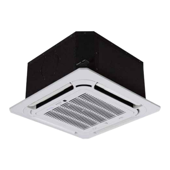
- Page 1 OWNER’S MANUAL MULTI-ZONE FOUR-WAY CASSETTE MODELS: 3PAMSCH12, 3PAMSCH18, 3PAMSCH24 Image shown is the 3PAMSCH12, 3PAMSCH18...
-
Page 2: Table Of Contents
TROUBLESHOOTING ................................16 ACCESSORIES ...........................18 INSTALLATION MANUAL INSTALLATION SUMMARY ......................19 UNIT PARTS ............................20 3PAMSCH12 & 3PAMSCH18 ..............................20 3PAMSCH24 ....................................21 INDOOR UNIT INSTALLATION .......................22 STEP 1: SELECT INSTALLATION LOCATION ..............................22 STEP 2: HANG INDOOR UNIT ....................................23 STEP 3: DRILL WALL HOLE FOR CONNECTIVE PIPING ..........................25 STEP 4: CONNECT DRAIN HOSE ................................... -
Page 3: Packing And Unpacking The Unit
Put the indoor unit into the package. PANEL INSTALLATION ........................40 Take out the accessories. Close the package and seal it. 3PAMSCH12 & 3PAMSCH18 ..............................40 Lift the machine out and lay it flat. Using the packing belt if necessary. STEP 1: REMOVE THE FRONT GRILLE ................................40 STEP 2: INSTALL THE PANEL .................................... -
Page 4: Safety Precautions
SAFETY & PRECAUTIONS SAFETY PRECAUTIONS SAFETY PRECAUTIONS (Continued) Read Safety Precautions Before Operation and Installation CAUTION ELECTRICAL WARNINGS Incorrect installation due to ignoring instructions can cause serious damage or injury. • Turn off the air conditioner and disconnect • Only use the specified power cord. If the power The seriousness of potential damage or injuries is classified as either a WARNING or CAUTION. -
Page 5: Best Installation Practices
SAFETY & PRECAUTIONS SAFETY PRECAUTIONS SAFETY PRECAUTIONS (Continued) (Continued) PRODUCT INSTALLATION WARNINGS BEST INSTALLATION PRACTICES Installation must be performed by an • A SURGE PROTECTOR IS HIGHLY RECOMMENDED TO PREVENT DAMAGE TO THE EQUIPMENT DUE Do not turn on the power until all work has authorized dealer or specialist. -
Page 6: Unit Specifications And Features
32°F - 122°F (0°C - 50°C) Infrared Manual 5°F - 75°F 32°F - 122°F 3PAMSCH12 & 3PAMSCH18 display receiver button Outdoor Temperature 5°F - 122°F (-15°C - 24°C) (0°C - 50°C) (-15°C - 50°C) -
Page 7: Other Features
SAFETY & PRECAUTIONS UNIT SPECIFICATIONS AND FEATURES CARE AND MAINTENANCE (Continued) OTHER FEATURES CLEANING YOUR INDOOR UNIT If using water, the inlet side If using a vacuum cleaner, • DEFAULT SETTING • LOUVER ANGLE MEMORY should face down and away the inlet side should face Some models are designed with a louver angle When the air conditioner restarts after a power... -
Page 8: Maintenance - Long Periods Of Non-Use
SAFETY & PRECAUTIONS CARE AND MAINTENANCE TROUBLESHOOTING (Continued) MAINTENANCE – MAINTENANCE – SAFETY PRECAUTIONS LONG PERIODS OF NON-USE PRE-SEASON INSPECTION If ANY of the following conditions occurs, turn off your unit immediately! If you plan not to use your air conditioner for an After long periods of non-use, or before periods •... -
Page 9: Troubleshooting
SAFETY & PRECAUTIONS TROUBLESHOOTING TROUBLESHOOTING (Continued) (Continued) Issue Possible Causes Problem Possible Causes Solution Low hissing sound during operation: This is normal and is caused by Power failure Wait for the power to be restored refrigerant gas flowing through both indoor and outdoor units. Both the indoor Low hissing sound when the system starts, has just stopped running, or is The power is turned off... -
Page 10: Installation Summary
SAFETY & PRECAUTIONS ACCESSORIES INSTALLATION SUMMARY The air conditioning system comes with the following accessories. Use all of the installation parts and accessories to install the air conditioner. Improper installation may result in water leakage, electrical shock and fire, or cause the equipment to fail. -
Page 11: Unit Parts
SAFETY & PRECAUTIONS UNIT PARTS UNIT PARTS (Continued) 3PAMSCH12 & 3PAMSCH18 3PAMSCH24 NOTE: The installation must be performed in accordance with the requirement of local and national standards. The installation may be slightly different in different areas. Air outlet Display panel... -
Page 12: Indoor Unit Installation
NOTE: Panel installation should be specifications. be 1.6”(4cm) larger than the body size. performedafter piping and wiring have been 3PAMSCH12 & 3PAMSCH18 completed. Be sure to mark the areas where ceiling hook Ceiling holes will be drilled. STEP 1: SELECT INSTALLATION LOCATION 3PAMSCH12 &... -
Page 13: Step 3: Drill Wall Hole For Connective Piping
NOTE: Ensure that the indoor unit is level. 3PAMSCH12 & 3PAMSCH18 The unit is equipped with a built-in drain pump STEP 4: CONNECT DRAIN HOSE and float switch. If the unit is tilted against the NOTE: The bottom of the unit should be 0.9”... - Page 14 Fix the sheath connector (not supply) on the Figure. tighten the indoor connection with an wire hole of the conduit installation plate. additional protection tube to prevent it 3PAMSCH12 & 3PAMSCH18 3PAMSCH12 & 3PAMSCH18 from pulling loose. Fix the the conduit installation plate on the Drain hose chassis of the unit.
-
Page 15: Outdoor Unit Installation
SAFETY & PRECAUTIONS OUTDOOR UNIT INSTALLATION OUTDOOR UNIT INSTALLATION (Continued) Install the unit by following local codes and DO NOT install unit in the following locations: STEP 2: INSTALL DRAIN JOINT STEP 3: ANCHOR OUTDOOR UNIT regulations , there may be differ slightly between ;... -
Page 16: Note On Pipe Length
SAFETY & PRECAUTIONS OUTDOOR UNIT INSTALLATION REFRIGERANT PIPING CONNECTION (Continued) When connecting refrigerant piping, do not let substances or gases other than the specified refrigerant Outdoor Unit Dimensions (in) Mounting Dimensions enter the unit. The presence of other gases or substances will lower the unit’s capacity, and can cause abnormally high pressure in the refrigeration cycle. -
Page 17: Connection Instructions - Refrigerant Piping
SAFETY & PRECAUTIONS REFRIGERANT PIPING CONNECTION REFRIGERANT PIPING CONNECTION (Continued) (Continued) CONNECTION INSTRUCTIONS – STEP 2: REMOVE BURRS Turn the handle of the flaring tool clockwise Align the center of the two pipes that you will REFRIGERANT PIPING until the pipe is fully flared. Flare the pipe in connect. -
Page 18: Wiring
SAFETY & PRECAUTIONS REFRIGERANT PIPING CONNECTION WIRING (Continued) BEFORE PERFORMING ANY To avoid getting an electric shock, never Thread this pipeline through the wall and NOTE ON MINIMUM BEND RADIUS touch the electrical components soon after connect it to the outdoor unit. ELECTRICAL WORK, READ Carefully bend the tubing in the middle the power supply has been turned off. -
Page 19: Outdoor Unit Wiring
SAFETY & PRECAUTIONS WIRING WIRING (Continued) (Continued) COMPACT MODELS OUTDOOR UNIT WIRING CAUTION Remove the electric cover of the outdoor unit. If there is no cover on the outdoor unit, take • While connecting the wires, please strictly off the bolts from the maintenance board and follow the wiring diagram. -
Page 20: Air Evacuation
SAFETY & PRECAUTIONS AIR EVACUATION AIR EVACUATION (Continued) PREPARATIONS AND PRECAUTIONS NOTE ON ADDING REFRIGERANT Close the Low Pressure side of the manifold Some systems require additional charging depending on pipe lengths. The standard pipe length varies Air and foreign matter in the refrigerant circuit gauge, and turn off the vacuum pump. -
Page 21: Panel Installation
Hang the four latches of the decorative panel to Push both of the tabs towards the middle 3PAMSCH12 & 3PAMSCH18 the hooks of the indoor unit. Tighten the panel simultaneously to unlock the hook on hook screws evenly at the four corners. -
Page 22: Step 4: Hang The Intake Grille
SAFETY & PRECAUTIONS PANEL INSTALLATION TEST RUN (Continued) e. Ensure the manual buttons on the indoor BEFORE TEST RUN STEP 4: HANG THE INTAKE GRILLE NOTE: If the height of the indoor unit needs unit works properly. to be adjusted, you can do so through the Hang the intake grille on the panel, and then A test run must be performed after the entire system Check to see that the drainage system is... - Page 23 5401 Dansher Road Countryside, IL 60525 844-4PA-AIRE 844-472-2473 support@perfectaire.us 877-997-2473 supportcanada@perfectaire.us CANADA SUPPORT www.perfectaire.us Printed in China 1221_M872...
Need help?
Do you have a question about the 3PAMSCH12 and is the answer not in the manual?
Questions and answers