Table of Contents
Advertisement
Advertisement
Table of Contents

Subscribe to Our Youtube Channel
Related Manuals for Mitsubishi Thermal Digiplater


Summary of Contents for Mitsubishi Thermal Digiplater
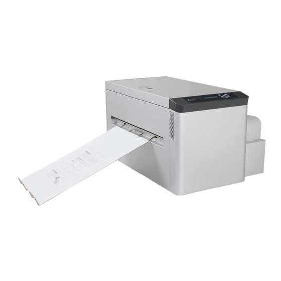
- Page 1 Thermal Digiplater TDP-459 User’s Manual MITSUBISHI PAPER MILLS, LTD.
- Page 3 If this manual is lost or damaged, promptly place an order for a new one from a distributor near you. If this THERMAL DIGIPLATER is transferred to another party, please attach this manual to the Thermal Digiplater.
-
Page 5: Table Of Contents
Table of Contents Chapter 1 Safety Precautions...............1 Cautions for working environment and installation ..........2 Handling the THERMAL DIGIPLATER................ 3 Kind of warning labels and its attachment part ............5 Handling plate before and after platemaking ............6 Chapter 2 Installation and Setup............7... - Page 6 3.3.10 Interval Set ..........................39 3.3.11 Adjusting the plate length in simple..................41 Chapter 4 Daily Maintenance............. 48 Cleaning the parts inside the THERMAL DIGIPLATER ........... 48 4.1.1 Cleaning the thermal head ....................49 4.1.2 Cleaning Main Pinch roller ....................51 4.1.3...
-
Page 7: Chapter 1 Safety Precautions
Thermal Digiplater is handled incorrectly. Indicates causes of problem or conditions of working environment. It is impossible for us to anticipate all hazards that may occur when the THERMAL DIGIPLATER is installed and used under various environmental conditions. Therefore, all possible warnings and cautions are not included in the user’s manual, other leaflets or labels on the THERMAL DIGIPLATER. -
Page 8: Cautions For Working Environment And Installation
Thermal Digiplater. If water is spilt or a metallic piece enters the Thermal Digiplater, a fire or electric shock can occur. Do not cover the vent holes of the Thermal Digiplater. Doing so will not allow the heat to escape from the Thermal Digiplater, thereby causing a fire. -
Page 9: Handling The Thermal Digiplater
As it weighs approximately 55 kg(121 lbs), it is dangerous for a single person to try to hold or carry the Thermal Digiplater . When taking it out of the package, take care not to injure your fingers or hands. - Page 10 Chapter 1 Safety Precautions Use only the power cable supplied with the Thermal Digiplater. Be sure to connect the power cable to the electric oulet to be grounded according to all relevant local regulations(resistance:less than 100 ohm). If a short circuit occurs while the Thermal Digiplater is operating without being grounded, a fire or electric shock can occur.
-
Page 11: Kind Of Warning Labels And Its Attachment Part
1.3 Kind of warning labels and its attachment part The following warning labels are attached inside the THERMAL DIGIPLATER to prevent the accident and avoid the danger. If the label come off or can’t be seen, contact the distributor from whom you... -
Page 12: Handling Plate Before And After Platemaking
When handling plate, observe the following instructions: When handling plate before platemaking: Use plate specified by Mitsubishi Paper Mills, Ltd. Wrap the plate with the black polybag and avoid high temperature and high humidity, and store it in the cool and dark place. -
Page 13: Chapter 2 Installation And Setup
Check the names and functions of the THERMAL DIGIPLATER’s parts. Take out the protective inserts. Connect the power cable. Connect the USB cable. Install the plate tray. Turn on the power switch. Set the spools to the plate and place the plate into the THERMAL DIGIPLATER. -
Page 14: Unpacking
This Thermal Digiplater weighs approx. 55 kg(121 lbs). Take care when handling it. When taking out and carrying, securely hold it by its bottom. Do not discard the packaging materials. The box and protective inserts will be required to transfer or transport the Thermal Digiplater. Keep them in a safe place. -
Page 15: Checking The Accessories
Chapter 2 Installation and Setup 2.3 Checking the accessories Take out the accessories from the box and from inside of the THERMAL DIGIPLATER. Check that the following items, as illustrated below, are present. (Flange(gear side)) (Spool shaft) Spool Flange(anti-gear side) -
Page 16: Names And Functions Of Parts
Chapter 2 Installation and Setup 2.4 Names and functions of parts 2.4.1 Names of parts Front Upper cover Opening lever A Operation panel Plate tray Power switch Rear Plate cover Power input terminal USB terminal Filters -10-... - Page 17 Chapter 2 Installation and Setup Inside the THERMAL DIGIPLATER Thermal head Cleaning roller (entrance side) Main pinch roller Platen roller Feeding pinch roller Cleaning roller (discharge side) -11-...
-
Page 18: Functions Of Parts
The operation buttons, LCD display (referred to as the LCD below) and status lamps are Operation panel located here. Switch to turn the power to the THERMAL DIGIPLATER on or off. Pressing “|” turns on the power while pressing “O” turns off the power. Power switch <Caution>... -
Page 19: Connecting The Power Cable
Be sure to connect the power cable to the electric outlet to be grounded according to all relevant local regulations(resistance:less than 100 ohm). If a short circuit occurs while the Thermal Digiplater is operating without being grounded, a fire or electric shock can occur. If the Thermal Digiplater cannot be grounded, consult the distributor. -
Page 20: Connecting The Usb Cable
If a cord is kept connected, it can be scratched, and a fire or electric shock can occur, or you can trip and be injured. If the Thermal Digiplater is not used for a long time, disconnect the power cable from the electric outlet for safety. -
Page 21: Installing The Plate Tray
Chapter 2 Installation and Setup 2.7 Installing the plate tray A plate cutter is installed inside the plate discharge port. Do not put fingers. Doing so can cause injure. Insert one of the claws of the plate tray into the corresponding mounting hole for the plate tray. -
Page 22: Setting The Plate
Chapter 2 Installation and Setup 2.8 Setting the plate Turn on the power to the THERMAL DIGIPLATER. Power switch Set the size of the plate to be installed on the operation panel. See 3.3.1 Selecting the plate size. By holding the opening lever B, open the plate cover. - Page 23 Chapter 2 Installation and Setup Take out the new plate from the black polybag. The plate weighs approx. 10 kg(22 lbs). Handle it carefully so as not to drop it. Dropping it is dangerous. Change the flange(gear side) position of the spool according to the size of the plate to be used.
- Page 24 Chapter 2 Installation and Setup Install and fit the flange(anti-gear side) to the end of the shaft on the opposite side of stopper the plate. Flange (anti-gear side) [Useful tip] The flange (anti-gear side) has a stopper notch and the shaft has stopper notches to prevent empty rotation.
- Page 25 Chapter 2 Installation and Setup Remove the seal fixing the end of the plate. And, cut off approx. 5cm of the leading edge of the plate to avoid mechanical trouble. Fixing seal Tear off and remove the seal completely. Entry of fragments of the seal into the feed path can cause trouble in feeding and/or printing.
- Page 26 Chapter 2 Installation and Setup Slowly close the plate cover. Be careful not to catch fingers when closing the plate cover. Plate cover Press the loading button on the operation panel. ready to road [Useful tip] If the size of the plate placed in this machine does not match the plate size set, the loading will not be completed correctly.
-
Page 27: Change Method Of Flange Position
Chapter 2 Installation and Setup 2.9 Change Method of Flange Position Please change the flange position of a spool according to the size of the plate to be used. Loosen the screw which secures the flange. Turns in the direction of the illustration arrow, applying a finger to the knob part of the fixed screw. - Page 28 Chapter 2 Installation and Setup Tighten the screw and fix flange. ・Turns in the direction of the illustration arrow, applying a finger to the knob part of a fixed screw. ・Please fasten securely, turning until the screw stops. (Flange set position and the relation of the range which can be printed) Relation between flange set position and print area is shown on diagram below.
-
Page 29: Chapter 3 Use Of Operation Panel
The power switch is located on the left side surface of this machine. Pressing the upper side (“l”) turns on the power while pressing the lower side (“O”) turns off the power. Power switch Before disconnecting the USB cable, make sure that the Thermal Digiplater is in the standby state. If disconnected during data transfer, incorrect printing can result. -
Page 30: Led Indications
Orange This lamp is on when the power is on. ready LED Green This lamp is on when the THERMAL DIGIPLATER is ready for printing. This lamp is on when an abnormality occurs in the THERMAL error LED DIGIPLATER. 3.2.2 Operation button The functions of the operation buttons are shown in the following table. -
Page 31: Lcd Indications
Chapter 3 Use of Operation Panel 3.2.3 LCD indications The LCD shows the THERMAL DIGIPLATER status as shown in the following table. Data shown on the LCD Description English Japanese Initializing The THERMAL DIGIPLATER is being initialized. ショキカチュウ Booting up The firmware is being started. -
Page 32: Explanation Of The User Mode
Chapter 3 Use of Operation Panel 3.3 Explanation of the user mode In the user mode, the following are possible: Items available in the user mode LCD indications Description English Japanese Plate Size Select the plate size. プレート サイズ Size Set Set a plate size. -
Page 33: Selecting The Plate Size
Chapter 3 Use of Operation Panel 3.3.1 Selecting the plate size In the ready state, press the menu button and display “Plate Size” on the LCD. Plate Size [Useful tip] Pressing the + or - button repeatedly changes the message on the LCD as shown below. -
Page 34: Setting The Plate Size
Chapter 3 Use of Operation Panel 3.3.2 Setting the plate size ■ Standard setting In the ready state, press the menu button once, press the + button once, and display “Size Set” on the LCD. Size Set [Useful tip] Pressing the + or - button repeatedly changes the message on the LCD as shown below. - Page 35 Chapter 3 Use of Operation Panel Press the enter button to set the plate width. Width: 459mm • It can be set from 310mm to 459mm in increments of 1mm. [Useful tip] To change values, use the following buttons: menu button: Increments the number by 10 + + + + button: Increments the number by 1 loading button: Decrement the number by 10 - button: Decrement the number by 1 Press the enter button to confirm the width setting.
- Page 36 Use of Operation Panel ■ Free size setting This mode is quite useful if you use several plate lengths with one width. THERMAL DIGIPLATER automatically fix the plate length depends on data size. In the ready state, press the menu button once, press the + button once, and display “Size Set”...
- Page 37 Chapter 3 Use of Operation Panel Press the enter button to set the plate width. Width: 459mm • It can be set from 310mm to 459mm in increments of 1mm. [Useful tip] To change values, use the following buttons: menu button: Increments the number by 10 + + + + button: Increments the number by 1 loading button: Decrement the number by 10 - button: Decrement the number by 1 Press the enter button to confirm the customized plate size name.
-
Page 38: Adjusting The Print Density
Chapter 3 Use of Operation Panel 3.3.3 Adjusting the print density In the ready state, press the menu button once, press the + button 2 times, display “Density” on the LCD. Density [Useful tip] Pressing the + or - button repeatedly changes the message on the LCD as shown below. -
Page 39: Checking The Firmware Versions
Chapter 3 Use of Operation Panel 3.3.4 Checking the firmware versions In the ready state, press the menu button once, press the + button 3 times, and Firmware Version display “Firmware Version” on the LCD. [Useful tip] Pressing the + or - button repeatedly changes the message on the LCD as shown below. -
Page 40: Display Of Plate Remains, And Reset Of Plate Remains Counter
Chapter 3 Use of Operation Panel 3.3.5 Display of Plate Remains, and Reset of Plate Remains Counter Display of plate remains and reset of plate remains counter are executed as follows. When reset is executed, plate remains counter is at the time of brand-new plate, and printed length is subtracted in increments of until reset is executed next time. -
Page 41: Display Of Print Counter, And Reset Of Print Counter
Chapter 3 Use of Operation Panel 3.3.6 Display of Print Counter, and Reset of Print Counter Display of print counter and reset of print counter are executed as follows. When reset is executed, print counter is「0」, and the number of the printed plates is added until reset is executed next time. -
Page 42: Setup Of Plate Remains Sw(On/Off)
Chapter 3 Use of Operation Panel 3.3.7 Setup of Plate Remains SW(on/off) In the ready state, press the menu button once, press the + button 6 times, and Remains Sw display ”Remains Sw” on the LCD. [Useful tip] Pressing the + or - button repeatedly changes the message on the LCD as shown below. -
Page 43: Execution Of Platen Cleaning
Chapter 3 Use of Operation Panel 3.3.8 Execution of Platen Cleaning This mode is used when executing the platen roller cleaning. Please refer to Chapter 4 about the cleaning method of the platen roller. In the ready state, press the menu button once,press the + botton 7 times and Platen Cleaning display “Platen cleaning”... -
Page 44: Display Of Accumulated Print Distance
Chapter 3 Use of Operation Panel 3.3.9 Display of accumulated print distance Displays accumulated print distance. This message is displayed only when Manage Count Sw is set at ON (factory setting). In the ready state, press the menu button once, press the + button 8 times, and Manage Count display ”Manage Count”... -
Page 45: Interval Set
The default setting is off. • This mode use particular counter. • The counter is reset whenever you turn off THERMAL DIGIPLATER. • It’s shown “print restart” in LCD and if you press the enter button, the counter is reset. - Page 46 Chapter 3 Use of Operation Panel Press the clear button repeatedly until the ready state is displayed. -40-...
-
Page 47: Adjusting The Plate Length In Simple
Chapter 3 Use of Operation Panel 3.3.11 Adjusting the plate length in simple This mode is used when plate length is adjusted in simple. Adjust using this function if you find incorrect image size. Print Length : Adjust image length (①) Top Offset : Adjust the length that is from the plate edge to the print end (②) Sensor Offset: Adjust the length that is from the print start to the plate edge (③) - Page 48 Chapter 3 Use of Operation Panel Adjustment of print length In the ready state, press the menu button once, press the + button 10 times, and Adjust Plate display ”Adjust Plate” on the LCD. [Useful tip] Pressing the + or - button repeatedly changes the message on the LCD as shown below.
- Page 49 Chapter 3 Use of Operation Panel Press the + , MENU or -, Loading button to change the setting of the adjustment value of print length. Print Length 0.5mm 【 【 【 【 Useful tip】 】 】 】 It can be set from -10.0 to +10.0 (mm), in increments of 0.1(mm). + button: +0.1 - button: -0.1 menu button: +1.0...
- Page 50 Chapter 3 Use of Operation Panel Adjustment of Top Offset length In the ready state, press the menu button once, press the + button 10 times, and Adjust Plate display ”Adjust Plate” on the LCD. [Useful tip] Pressing the + or - button repeatedly changes the message on the LCD as shown below.
- Page 51 Chapter 3 Use of Operation Panel Press the + , MENU or -, Loading button to change the setting of the adjustment value of Top Offset.. Top Offset 0.5mm 【 【 【 【 Useful tip】 】 】 】 It can be set from -10.0 to +10.0 (mm), in increments of 0.1(mm). + button: +0.1 - button: -0.1 menu button: +1.0...
- Page 52 Chapter 3 Use of Operation Panel Adjustment of Sensor Offset length In the ready state, press the menu button once, press the + button 10 times, and Adjust Plate display ”Adjust Plate” on the LCD. [Useful tip] Pressing the + or - button repeatedly changes the message on the LCD as shown below.
- Page 53 Chapter 3 Use of Operation Panel Press the + , MENU or -, Loading button to change the setting of the adjustment value of Sensor Offset. Sensor Offset 0.5mm 【 【 【 【 Useful tip】 】 】 】 It can be set from -10.0 to +10.0 (mm), in increments of 0.1(mm). + button: +0.1 - button: -0.1 menu button: +1.0...
-
Page 54: Chapter 4 Daily Maintenance
Chapter 4 Daily Maintenance Chapter 4 Daily Maintenance 4.1 Cleaning the parts inside the THERMAL DIGIPLATER To keep the best print quality, clean the thermal head, image sensor, head-position plate, platen roller, cleaning rollers and the main pinch roller by following the steps as instructed below. Please clean at the following frequency. -
Page 55: Cleaning The Thermal Head
Do not touch it directly by hand. Fingerprints on the thermal head heating element can cause the thermal head to fail. Do not touch it directly by hand. Be careful not to be injured by protrusions in the Thermal Digiplater. -49-... - Page 56 Chapter 4 Daily Maintenance Then, wipe the thermal head using the lapping film (3M Lapping film Aluminum Oxide 261X, The heating element Grain size/ 3 micron (pink) sheet) and remove the dirt completely. • The dirt can not see visually on the head, but you can see the streak image on the plate.
-
Page 57: Cleaning Main Pinch Roller
Chapter 4 Daily Maintenance 4.1.2 Cleaning Main Pinch roller By holding the opening lever A on the top of the upper cover, open the upper cover. Opening lever A Do not open the upper cover extremely quickly or forcibly 90 degrees or more. Upper cover Locking lever [Useful tip]... - Page 58 Chapter 4 Daily Maintenance Release the locking lever and close the upper cover slowly. Upper cover Locking lever Set a plate if you pick a plate out of the machine. -52-...
-
Page 59: Cleaning Platen Roller
Chapter 4 Daily Maintenance 4.1.3 Cleaning Platen roller By holding the opening lever A on the top of the upper cover, open the upper cover. Opening lever A Do not open the upper cover extremely quickly or forcibly 90 degrees or more. Upper cover Locking lever [Useful tip]... - Page 60 (It is recommended that the Thermal Digiplater be left for about 5 minutes after cleaning .) Do not put your hand or cleaning cloth close to the inside of the Thermal Digiplater during the platen roller rotation. Release the locking lever and close the upper cover slowly.
-
Page 61: Cleaning Feeding Pinch Roller
Chapter 4 Daily Maintenance 4.1.4 Cleaning feeding pinch roller By holding the opening lever A on the top of the upper cover, open the upper cover. Opening lever A Do not open the upper cover extremely quickly or forcibly 90 degrees or more. Upper cover Locking lever [Useful tip]... - Page 62 (It is recommended that the Thermal Digiplater be left for about 5 minutes after cleaning .) Do not put your hand or cleaning cloth close to the inside of the Thermal Digiplater during the platen roller rotation. Fit on the feeding pinch roller (upper roller), and release the locking lever and close the upper cover slowly.
-
Page 63: Cleaning The Cleaning Rollers
Chapter 4 Daily Maintenance 4.1.5 Cleaning the cleaning rollers By holding the opening lever A on the top of the upper cover, open the upper cover. Opening lever A Do not open the upper cover extremely quickly or forcibly 90 degrees or more. Upper cover Locking lever [Useful tip]... - Page 64 Chapter 4 Daily Maintenance Release the locking lever and close the upper cover slowly. Upper cover Locking lever Set a plate if you pick a plate out of the machine. -58-...
-
Page 65: Cleaning Image Sensor
Chapter 4 Daily Maintenance 4.1.6 Cleaning Image sensor By holding the opening lever A on the top of the upper cover, open the upper cover. Opening lever A Do not open the upper cover extremely quickly or forcibly 90 degrees or more. Upper cover Locking lever [Useful tip]... - Page 66 Chapter 4 Daily Maintenance Release the locking lever and close the upper cover slowly. Upper cover Locking lever Set a plate if you pick a plate out of the machine. -60-...
-
Page 67: Cleaning The Head-Position Plate
Chapter 4 Daily Maintenance 4.1.7 Cleaning the head-position plate By holding the opening lever A on the top of the upper cover, open the upper cover. Opening lever A Do not open the upper cover extremely quickly or forcibly 90 degrees or more. Upper cover Locking lever [Useful tip]... - Page 68 Chapter 4 Daily Maintenance Release the locking lever and close the upper cover slowly. Upper cover Locking lever -62-...
-
Page 69: Cleaning The Cover Of The Thermal Digiplater
4.2 Cleaning the cover of the THERMAL DIGIPLATER To remove dirt, wipe the cover of the THERMAL DIGIPLATER with a dry soft cloth. If dirt cannot be removed by wiping with a dry cloth, lightly wipe the cover with a damped cloth which has been soaked in water or a little diluted neutral detergent. -
Page 70: Periodical Replacement Parts
Daily Maintenance 4.4 Periodical replacement parts The periodical replacement parts for the THERMAL DIGIPLATER are shown on the following table. If you would like to know a time for replacement, please consult the distributor from whom you bought the product. - Page 71 Chapter 4 Daily Maintenance (MEMO) -65-...
-
Page 72: Chapter 5 Troubleshooting
DIGIPLATER cannot be restored by turning temperature sensor the power off and on, it may be necessary to Temp Sens Err * repair the THERMAL DIGIPLATER. Consult THERMAL DIGIPLATER is defective. Service department. Problem in the sensor system of the Sensor Error *... -
Page 73: Warning Message
[Useful tip] There are two kind of warning messages, Warning 01 and 02. Pless the clear button clear for more than 2 seconds to clear the warning message. Warning 01 And THERMAL DIGIPLATER is ready to print work. Size01: 324x492 -67-... -
Page 74: Plate Jam
Do not touch it directly by hand. Fingerprints on the thermal head heating element can cause the thermal head to fail. Do not touch it directly by hand. Be careful not to be injured by protrusions in the Thermal Digiplater. -68-... - Page 75 Chapter 5 Troubleshooting When there is no plate left Turn on the power switch. Power switch Reset the plate. See 2.8 Setting the plate. -69-...
- Page 76 Chapter 5 Troubleshooting When there is plate left Open the plate cover and pull the plate out with your hands. Do not open the plate cover extremely quickly or forcibly 90 degrees or more. Plate If the plate cannot be pulled out, cut off the jammed and folded sections with scissors, and pull the plate out.
-
Page 77: When Parts Of Image Area Are Missing From The Printed Plate
Chapter 5 Troubleshooting 5.4 When parts of image area are missing from the printed plate Incorrect print with straight streaky missing parts in the direction of plate feed This may have been caused by contamination on the thermal head. Clean it as instructed in 4.1.1 Cleaning the thermal head (page 49) . -
Page 78: Plate Is Not Correctly Detected
Do not touch it directly by hand. Be careful not to be injured by protrusions in the Thermal Digiplater. [Useful tip] A locking lever is provided to the upper cover to prevent the cover from closing down. - Page 79 Chapter 5 Troubleshooting Wipe plate sensors with recommended cleaning cloth soaked in the abequate amount of recommended cleaning fluid. [Useful tip] Insert the cotton swab into each of the eight holes, as indicated in the circles in the above photo, and wipe off contamination by moving the cotton swab in a circular pattern in the hole.
-
Page 80: When Power Is Off During Printing
Chapter 5 Troubleshooting 5.6 When power is off during printing Power outage Power cable accidentally disconnected If power is off during printing, the thermal head remains pressed to the platen roller. Leaving this condition uncorrected for an extended period may cause deformation of the rubber on the platen roller. To prevent the rubber from being deformed, perform the following steps as instructed below. - Page 81 Chapter 5 Troubleshooting (MEMO) -75-...
-
Page 82: Chapter 6 After-Sales Service
Chapter 6 After-sales service Chapter 6 After-sales service If you would like to inquire about the product or request a repair, please consult the distributor from whom you bought the product. -76-... - Page 83 Chapter 6 After-sales service (MEMO) -77-...
-
Page 84: Chapter 7 Specification
Chapter 7 Specification Chapter 7 Specification 7.1 Basic specification Item Specification Print system Direct thermal system Resolution 1203.8 DPI Dot pitch for crosswire direction : 0.0211mm Dot pitch for lengthwise direction : 0.0211mm Plate size (Width x Length) 310mm x 150mm ~ 459mm x 530mm Maximum recording width 360mm Print speed... - Page 85 Chapter 7 Specification (MEMO) TDP-459 -79-...
- Page 86 Chapter 7 Specification Mitsubishi Imaging (MPM), Inc. 555 Theodore Fremd Avenue, Rye, N.Y. 10580, USA Tel. +1 914-925-3200, Fax. +1 914-921-2495 www.mitsubishiimaging.com Mitsubishi Paper GmbH Am Albertussee 1, D-40549, Duesseldorf, Germany Tel. +49 211-53596-206, Fax. +49 211-53596-222 www.mitsubishi-paper.com MITSUBISHI PAPER MILLS LIMITED...
Need help?
Do you have a question about the Thermal Digiplater and is the answer not in the manual?
Questions and answers