Table of Contents
Advertisement
Quick Links
Advertisement
Table of Contents

Subscribe to Our Youtube Channel
Related Manuals for Mitsubishi TDP-324


Summary of Contents for Mitsubishi TDP-324
- Page 2 ...
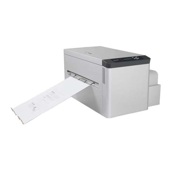
- Page 3 Introduction Thank you for purchasing this THERMAL DIGIPLATER TDP-324 made by MITSUBISHI PAPER MILLS, LTD. Read this manual carefully before using the Thermal Digiplater and become familiar with the installation and operation procedures. Keep this user’s manual at hand so that it can be referred to at any time during operation of the Thermal Digiplater.
-
Page 5: Table Of Contents
Execution of Platen Cleaning ....................41 3.3.10 Setting the Pinch Cleaning Mode and Execution of Pinch Cleaning ........42 3.3.11 Display of accumulated print distance................... 46 3.3.12 Set up a print Interval ......................47 Chapter 4 Daily Maintenance..............49 TDP-324 Table of Contents - 1... - Page 6 When parts of image area are missing from the printed plate....... 71 Plate is not correctly detected ................. 72 When power is off during printing ................74 Chapter 6 After-sales service ............75 Chapter 7 Specification..............77 Basic specification ....................77 Outline figure ......................77 TDP-324 Table of Contents - 2...
-
Page 7: Chapter 1 Safety Precautions
Should the Thermal Digiplater be used for any purposes other than as intended in the user’s manual, you shall be solely responsible for the safety. Never perform operations that are prohibited in the user’s manual and other leaflets. TDP-324... -
Page 8: Cautions For Working Environment And Installation
Do not install the Thermal Digiplater in an area with an extremely low or high temperature. Do not install it, for example, in an area of a ski site or skating rink with a low ambient temperature or in an outdoor area where it will be exposed to direct sunlight and heat. TDP-324... -
Page 9: Handling The Thermal Digiplater
It is heated to a high temperature. Never touch it. If an abnormality occurs, take only the measures for the abnormalities described in this users manual. If normal operation cannot be recovered, contact the distributor from whom you bought it. TDP-324... - Page 10 If hard particles, such as sand, enter the head, it can be damaged. Take care when handling the head. Use the USB cable supplied with the Thermal Digiplater to connect it to your computer when installing the Thermal Digiplater. TDP-324...
-
Page 11: Kind Of Warning Labels And Its Attachment Part
1.3 Kind of warning labels and its attachment part The following warning labels are attached inside the Thermal Digiplater to prevent the accident and avoid the danger. If the label come off or can’t be seen, contact the distributor from whom you bought it immediately. TDP-324... -
Page 12: Handling Plate Before And After Platemaking
When handling plate, observe the following instructions: When handling plate before platemaking: Use plate specified by Mitsubishi Paper Mills, Ltd. Wrap the plate with the black polybag and avoid high temperature and high humidity, and store it in the cool and dark place. -
Page 13: Chapter 2 Installation And Setup
Check the names and functions of the Thermal Digiplater’s parts. Take out the protective inserts. Connect the power cable. Connect the USB cable. Install the plate tray. Turn on the power switch. Set the spools to the plate and place the plate into the Thermal Digiplater. TDP-324... -
Page 14: Unpacking
This Thermal Digiplater weighs approx. 55 kg(121 lbs). Take care when handling it. When taking out and carrying, securely hold it by its bottom. Do not discard the packaging materials. The box and protective inserts will be required to transfer or transport the Thermal Digiplater. Keep them in a safe place. TDP-324... -
Page 15: Checking The Accessories
Take out the accessories from the box and from inside of the Thermal Digiplater. Check that the following items, as illustrated below, are present. (Flange(gear side)) (Spool shaft) Spool Flange(anti-gear side) Power cable USB cable Plate tray User’s manual Product warranty Technical guide TDPController CD-ROM If an accessory is missing, contact the distributor immediately. TDP-324... -
Page 16: Names And Functions Of Parts
Chapter 2 Installation and Setup 2.4 Names and functions of parts 2.4.1 Names of parts Front Upper cover Opening lever A Operation panel Plate tray Power switch Rear Plate cover Power input terminal USB terminal Filters TDP-324 -10-... - Page 17 Chapter 2 Installation and Setup Inside the Thermal Digiplater Thermal head Cleaning roller (entrance side) Main pinch roller Platen roller Feeding pinch roller Cleaning roller (discharge side) TDP-324 -11-...
-
Page 18: Functions Of Parts
Rubber rollers to remove dust and foreign matters from the plate surface. (Entrance and discharge One installed at the entrance side and the other at the discharge side. sides) Filter Prevent dust and foreign substances in air from entering inside the Thermal Digiplater. TDP-324 -12-... -
Page 19: Connecting The Power Cable
Do not scratch, damage or rework the power cable. Do not put a heavy article on the cable. Do not pull or forcibly bend it. Doing so can damage the power cable and cause a fire or electric shock. TDP-324 -13-... -
Page 20: Connecting The Usb Cable
Use only the USB cable supplied with the product or a specified one. If a cable other than the supplied cable is used, incorrect printing can result. Before disconnecting the USB cable, make sure that the Thermal Digiplater is in the standby state. If disconnected during data transfer, the Thermal Digiplater can be damaged. TDP-324 -14-... -
Page 21: Installing The Plate Tray
Stopper Secure the tray by inserting the bottom of the stopper into the stopper slit. Stacking quantity is up to 5 plates on the plate tray. Do not stack more than 5 plates on it. TDP-324 -15-... -
Page 22: Setting The Plate
Plate roll lead edge of the plate and lift up the plate with the spool, and take it out. The plate weighs approx. 10 kg(22 lbs). Handle it carefully so as not to drop it. Dropping it is dangerous. TDP-324 -16-... - Page 23 As the outer diameter of the flange is larger than the outer diameter of the plate, it is recommended that this work is performed with the right-hand side of the plate protruding from the work table. TDP-324 -17-...
- Page 24 Do not tighten the screw too much. It may damage flange. Install the plate by placing the spool into the plate box. The plate weighs approx. 10 kg(22 lbs). Handle it carefully so as not to drop it. Dropping it is dangerous. TDP-324 -18-...
- Page 25 The motor will stop when the plate setting is completed. When the plate setting is completed, the ”NG” LED lamp goes off and “OK” LED lamp turns on. TDP-324 -19-...
- Page 26 Plate moves back and forth, and set the skew right. Then cut 2 plates with about 310mm(12.2inches) and discharge them forcibly. ・ When loading button is pressed for more than 2 seconds, the plate is not cut off. Please refer to “3.2.2 Operation button”. TDP-324 -20-...
-
Page 27: Change Method Of Flange Position
• indications of 2 to 5 and B, however these are not used in this product (TDP-324) Spool shaft The field of a flange inner side meets with a line. Flange Example: When setting to flange position "2” The line on the left-hand side of number "2"... - Page 28 Range which can be printed Print start side Example: The relation of the plate and the range which can be printed in the case of setting a flange to "1" and using a plate with a width of 324mm. TDP-324 -22-...
-
Page 29: Chapter 3 Use Of Operation Panel
3.2 Operation panel The buttons, LED lamps and LCD on the operation panel are explained below. + button LCD display screen menu button loading button power LED ready LED error LED clear button enter button - button TDP-324 -23-... -
Page 30: Led Indications
Use this button to exit the currently selected menu item in the user mode. + button Use this button to select an item from the menu in the user mode. - button Use this button to select an item from the menu in the user mode. TDP-324 -24-... -
Page 31: Lcd Indications
In the case of the plate remaining swittch off The Thermal Digiplater is ready for printing. *1.Selected plate size channel number is displayed. Custom channel: □□□ □□.□×□□.□ □□□ □□.□×□□.□ Free mode channel: F01 *4.Set plate name (size) is displayed. TDP-324 -25-... -
Page 32: Explanation Of The User Mode
[Plate Size] [Size Set] [Density] [Firmware Version] [Head Cleaning] [Plate] [Counter] [Remains Sw] [Platen Cleaning] [Pinch Cleaning] [Manage Count] [Interval Set] LCD message cycle when + button is pressed repeatedly LCD message cycle when - button is pressed repeatedly TDP-324 -26-... -
Page 33: Selecting A Plate Size Channel
In case of Inch Mode, it will be shown in inches, as shown below. [Size01:12.7×19.3] Press the enter button to select the desired plate size channel. Size01: 324×492 Press the clear button repeatedly until the ready state is displayed. TDP-324 -27-... -
Page 34: Setting The Plate Size
8 types as shown below. ,279,286,292,305,310,318,324(mm) • In case of Inch Mode, it can be selected from 8 types as shown below. The size, 254mm(10.00 inch), isn’t available on TDP-324 though you choose it. 10.00 ,11.00,11.25,11.5,12.00,12.19,12.50, 12.75(inch) The size, 254mm(10.00) is only available at the specific model, TDP-324B. - Page 35 10. + button:2-digit decimal number area is incremented by 1. - button: 2-digit decimal part decremented by 1 Press the enter button to confirm the length setting. Press the clear button repeatedly until the ready state is displayed. TDP-324 -29-...
-
Page 36: Adjusting The Print Density
101% [Useful tip] The density can be adjusted within -20% to +40%, in increments of 1%. Press the enter button to confirm the changed density. Density 101% Press the clear button repeatedly until the ready state is displayed. TDP-324 -30-... -
Page 37: Checking The Firmware Versions
Press the enter button to select the operation for checking firmware versions. MAIN Ver. ** . ** Press the + or - button to display another firmware version. TABLE Ver. ** . ** Press the clear button repeatedly until the ready state is displayed. TDP-324 -31-... -
Page 38: Setting The Head Cleaning Mode And Execution Of Head Cleaning
Press the + or - button to change the setting (on/off) of head cleaning mode. Cleaning Sw:on Press the enter button to confirm the setting (normal/Special) of head cleaning mode. Cleaning Sw:on Press the clear button repeatedly until the ready state is displayed. TDP-324 -32-... - Page 39 Press the + or - button to change the setting (Normal/Special) of head cleaning mode. Special Press the enter button to select the operation for setting the state (Normal/Special) of head cleaning mode. Special Press the clear button repeatedly until the ready state is displayed. TDP-324 -33-...
- Page 40 When the setting value is enlarged, the effect of head cleaning becomes large, but cleaning time becomes long. Press the enter button to confirm the setting of the special length. Cleaning Len 50 Press the clear button repeatedly until the ready state is displayed. TDP-324 -34-...
- Page 41 When the setting value is enlarged, the effect of head cleaning becomes large, but cleaning time becomes long. Press the enter button to confirm the setting of the special length. Special Length10 Press the clear button repeatedly until the ready state is displayed. TDP-324 -35-...
- Page 42 When “1” is selected, the head cleaning is executed every time. When “100” is selected, the head cleaning is executed every 100 prints. Press the enter button to confirm the setting of cleaning interval. Cleaning Num100 Press the clear button repeatedly until the ready state is displayed. TDP-324 -36-...
- Page 43 LCD. Press the enter button once, press the + button until ”Cleaning” displays on the LCD. Cleaning Press the enter button to execute head cleaning. Cleaning Press the clear button repeatedly until the ready state is displayed. TDP-324 -37-...
-
Page 44: Display Of Plate Remains, And Reset Of Plate Remains Counter
※.Press the clear button when not resetting. ・ ・ ・ ・ In case of Feet Mode, it will be shown in feets, as shown, [Plate 246 ft] Press the clear button repeatedly until the ready state is displayed. TDP-324 -38-... -
Page 45: Display Of Print Counter, And Reset Of Print Counter
Press the enter button to come to the state which can reset print counter. Reset? Press the enter button to reset print counter. * Press the clear button when not resetting. Counter Press the clear button repeatedly until the ready state is displayed. TDP-324 -39-... -
Page 46: Setup Of Plate Remains Sw(On/Off)
Press the + or - button to change the state (on/off) of “Remains SW”. Remains Press the enter button to confirm the setting of “Remains SW. Remains Press the clear button repeatedly until the ready state is displayed. TDP-324 -40-... -
Page 47: Execution Of Platen Cleaning
After closing Upper cover, press the enter button once, and a platen roller rotates 60 Now rotating degrees. If you want to clean up a entire roller, please repeat this 6 times. Press the clear button repeatedly until the ready state is displayed. TDP-324 -41-... -
Page 48: Setting The Pinch Cleaning Mode And Execution Of Pinch Cleaning
Print Length 500 [Useful tip] It can be set from 100mm to 500mm, in increments of 1mm. When the setting value is enlarged, the effect of head cleaning becomes large, but cleaning time becomes long. TDP-324 -42-... - Page 49 Press the + or - button to change the setting of the print number. Print Num [Useful tip] It can be set from 1 to 5, in increments of 1. When the setting value is enlarged, the effect of head cleaning becomes large, but cleaning time becomes long. TDP-324 -43-...
- Page 50 【 【 【 【 Useful tip】 】 】 】 It can be set from 1 to 10, in increments of 1. When the setting value is enlarged, the effect of head cleaning becomes large, but cleaning time becomes long. TDP-324 -44-...
- Page 51 LCD. Press the enter button once, press the + button until ”Cleaning” displays on the LCD. Cleaning Press the enter button to execute head cleaning. Cleaning Press the clear button repeatedly until the ready state is displayed. TDP-324 -45-...
-
Page 52: Display Of Accumulated Print Distance
・In case of Millimeter mode, accumulated print distance is shown in meter. ・In case of Inch mode, accumulated print distance is shown in feet. (unit is omitted) Press the clear button repeatedly until the ready state is displayed. TDP-324 -46-... -
Page 53: Set Up A Print Interval
Increment the number by 100, + button: Increment the number by 10 loading button: Decrement the number by 100, - button: Decrement the number by 10 Press the clear button repeatedly until the ready state is displayed. TDP-324 -47-... - Page 54 Chapter 3 Use of Operation Panel (MEMO) TDP-324 -48-...
-
Page 55: Chapter 4 Daily Maintenance
Image with many halftone does is apt to get it dirty, and there sometimes needs to be cleaned several times a day. • Once a week Main pinch roller Platen roller Feeding roller Cleaning rollers • Once a month Image sensor Head-position plate TDP-324 -49-... -
Page 56: Cleaning The Thermal Head
Do not touch it directly by hand. Fingerprints on the thermal head heating element can cause the thermal head to fail. Do not touch it directly by hand. Be careful not to be injured by protrusions in the Thermal Digiplater. TDP-324 -50-... - Page 57 Wipe heating element with recommended cleaning cloth soaked in the adequate amount of recommended cleaning fluid. Release the locking lever and close the upper cover slowly. Upper cover Locking lever TDP-324 -51-...
-
Page 58: Cleaning The Main Pinch Roller
When the plate is set, pull it out with your hands. Wipe the main pinch roller with a recommended cleaning cloth soaked in the adequate amount of recommended cleaning fluid. Main pinch roller TDP-324 -52-... - Page 59 Chapter 4 Daily Maintenance Release the locking lever and close the upper cover slowly. Upper cover Locking lever Reset the plate. TDP-324 -53-...
-
Page 60: Cleaning The Platen Roller
"Platen cleaning mode" in the 3.3.9 section, and clean the entire circumferences of the rubber part. In order to clean the entire circumferences of the • rubber part, it is necessary to repeat operation of "3." in the 3.3.9th section at least 6 times. TDP-324 -54-... - Page 61 Do not put your hand or cleaning cloth close to the inside of the Thermal Digiplater during the platen roller rotation. Release the locking lever and close the upper cover slowly. Upper cover Locking lever Reset the plate. TDP-324 -55-...
-
Page 62: Cleaning The Feeding Pinch Roller
When the plate is set, pull it out with your hands. Remove the upper feeding roller, and wipe the white roller part with a recommended cleaning cloth soaked in the adequate amount of recommended cleaning fluid. feeding pinch roller TDP-324 -56-... - Page 63 In order to clean the entire circumferences of the • rubber part, it is necessary to repeat operation of "3." in the 3.3.9th section at least 6 times. Release the locking lever and close the upper cover slowly. Upper cover Locking lever Reset the plate. TDP-324 -57-...
-
Page 64: Cleaning The Cleaning Rollers
When the plate is set, pull it out with your hands. Wipe cleaning rollers with recommended cleaning cloth soaked in the adequate amount of recommended cleaning fluid. Cleaning rollers [Useful tip] Cleaning rollers are provided on the entrance and discharge sides. TDP-324 -58-... - Page 65 Chapter 4 Daily Maintenance Release the locking lever and close the upper cover slowly. Upper cover Locking lever Reset the plate. TDP-324 -59-...
-
Page 66: Cleaning The Image Sensor
When opening the upper cover, be sure to open it to the position where the locking lever locks effectively. Wipe image sensor with recommended cleaning cloth soaked in the adequate amount of recommended cleaning fluid. Image sensor TDP-324 -60-... - Page 67 Chapter 4 Daily Maintenance Release the locking lever and close the upper cover slowly. Upper cover Locking lever TDP-324 -61-...
-
Page 68: Cleaning The Head Position Plate
When opening the upper cover, be sure to open it to the position where the locking lever locks effectively. Wipe the head-position plate with a recommended cleaning cloth soaked in the adequate amount of recommended cleaning fluid, applying it overall and uniformly, and moving it from side to side. Head-position plate TDP-324 -62-... - Page 69 Chapter 4 Daily Maintenance Release the locking lever and close the upper cover slowly. Upper cover Locking lever TDP-324 -63-...
-
Page 70: Cleaning The Cover Of The Thermal Digiplater
If the surfaces are wiped with a volatile liquid, such as benzine or thinner, or sprayed with insecticide, they can become discolored or cracked. 4.3 Cleaning the filters If it gets dust on the vent holes and filters, clean them with a vacuum cleaner. Vent holes Filters TDP-324 -64-... -
Page 71: Consumable Parts
Consumable parts for the Thermal Digiplater are shown on the following table. Name Thermal head(Assembly) Cleaning roller Cutter unit Filter *Available supply period for consumable parts is 5 years after it is discontinued. *It will be informed separately about discontinuing the product. TDP-324 -65-... - Page 72 Chapter 4 Daily Maintenance (MEMO) TDP-324 -66-...
-
Page 73: Chapter 5 Trouble Shooting
Problem in the sensor system of the Sensor Error * Thermal Digiplater * The messages on the LCD show a code number for service in the boxes ( When consulting Service department, please quote a code number. TDP-324 -67-... -
Page 74: Plate Jam
Do not touch it directly by hand. Fingerprints on the thermal head heating element can cause the thermal head to fail. Do not touch it directly by hand. Be careful not to be injured by protrusions in the Thermal Digiplater. TDP-324 -68-... - Page 75 Chapter 5 Trouble shooting When there is no plate left Turn on the power switch. Power switch Reset the plate. See 2.8 Setting the plate. TDP-324 -69-...
- Page 76 Do not open the plate cover extremely quickly or forcibly 90 degrees or more. Plate If the plate cannot be pulled out, cut off the jammed and folded sections with scissors, and pull the plate out. Reset the plate. See 2.8 Setting the plate. TDP-324 -70-...
-
Page 77: When Parts Of Image Area Are Missing From The Printed Plate
If this problem cannot be solved by cleaning, the head may be broken. Consult Service department. Incorrect print with dotted missing parts This may have been caused by contamination on the cleaning rollers. Clean them as instructed in Chapter 4 , 4.1 Cleaning the parts inside the Thermal Digiplater . TDP-324 -71-... -
Page 78: Plate Is Not Correctly Detected
Thermal Digiplater. [Useful tip] A locking lever is provided to the upper cover to prevent the cover from closing down. When opening the upper cover, be sure to open it to the position where the locking lever locks effectively. TDP-324 -72-... - Page 79 Release the locking lever to slowly close the upper cover. Upper cover Be careful not to catch fingers when closing the upper cover. Locking lever TDP-324 -73-...
-
Page 80: When Power Is Off During Printing
Push the corners of the upper cover strongly(see the photo on the right) until clicking noise can be heard. If “Plate Jam” is displayed on the LCD on the operation panel, follow the instructions as described in 5.2 Plate jam. TDP-324 -74-... -
Page 81: Chapter 6 After-Sales Service
Chapter 6 After-sales service Chapter 6 After-sales service If you would like to inquire about the product or request a repair, please consult the distributor from whom you bought the product. TDP-324 -75-... - Page 82 Chapter 7 After-sales service (MEMO) TDP-324 -76-...
-
Page 83: Chapter 7 Specification
Height 383mm×Width 515mm×Depth 663mm (Body) Weight Approx 55kg(Body) • Specification for this machine is subject to change without notice continual improvements. • In case of TDP-324B, a width of 254mm (10.00 inch) is available additionally. 7.2 Outline figure TDP-324 -77-... - Page 84 Chapter 7 After-sales service (MEMO) TDP-324 -78-...
Need help?
Do you have a question about the TDP-324 and is the answer not in the manual?
Questions and answers