Advertisement
Quick Links
S i 8 9 0
D
X
I G I TA L
M
ONITORING
1. Introduction
The Si890x are isolated ADCs suitable for low-frequency analog data acquisition applications. These devices
integrate an isolated 10-bit SAR ADC with I
5 kV are available. See the Si8900 data sheet for details.
2. Kit Contents
The Si890xPWR-EVB Evaluation kit contains the following items:
Si890xPWR-EVB evaluation module containing:
High voltage 110 V/220 V ac line current and voltage measurement circuit with 3.3 Vpp analog output signals
Si8900 Isolated 10-bit ADC with UART serial port
Si8901 Isolated 10-bit ADC with I
Si8902 Isolated 10-bit ADC with SPI serial port
C8051F007 mixed-signal MCU master controller
AC line-side bias supply
2.1. Hardware Overview
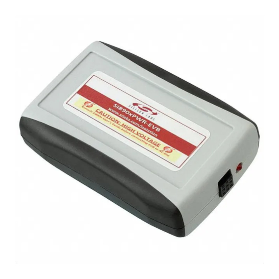
The Si890xPWR-EVB (Figure 1) demonstrates 50/60 Hz ac line voltage and current measurements. This EVB is
housed in a plastic case with recessed connectors to protect against user electrical shock. The Si890x accepts a
110 or 220 Vac input and supports load currents up to 10 A (max). The on-board line side circuit interface
measures ac voltage and current, which is then digitized by the Si890x on-chip 10-bit ADC. The resulting converted
data is then transmitted through the output side isolated serial port to the on-board master processor (C8051F007
MCU). The C8051F007 converts the serial data back to analog format where it is available to the user at the low-
voltage side of the evaluation module.
Key features for this EVB include the following:
EVB module measures ac line voltage (110 Vac or 220 Vac at 50/60 Hz) and ac line current (10 A max)
10-bit ADC with three input channels and selectable, isolated serial ports: UART (Si8900) or I
(Si8902)
High common mode transient immunity (CMTI): 35 kV/µs (min), 50 kV/µs (typ)
Industrial temperature operating range (–40 to +85
60-year isolation barrier life at rated working voltage
Safety certified (pending)
CSA component notice 5A approval
IEC 60950, 61010, 60601
VDE/IEC 60747-5-2
UL1577 recognized: (Up to 5 kVrms for 1 minute)
Danger! High Voltage: Read instructions carefully. Do not operate this evaluation board unless it is
housed in its plastic case and secured by the four screws.
Rev. 1.1 10/12
I
SOLATOR
A D C U
'
SER
S
2
C, UART, or SPI serial communication ports. Isolation ratings of 2.5 or
2
C serial port
Copyright © 2012 by Silicon Laboratories
S i 8 9 0 x - P W R - E V B
- B
, 1 0 - B
ASED
G
UIDE
°
C)
I
IT
SOLATED
2
C (Si8901) or SPI
Si890x-PWR-EVB
Advertisement

Related Manuals for Silicon Laboratories Si890x-PWR-EVB


Summary of Contents for Silicon Laboratories Si890x-PWR-EVB
- Page 1 UL1577 recognized: (Up to 5 kVrms for 1 minute) Danger! High Voltage: Read instructions carefully. Do not operate this evaluation board unless it is housed in its plastic case and secured by the four screws. Rev. 1.1 10/12 Copyright © 2012 by Silicon Laboratories Si890x-PWR-EVB...
- Page 2 Si890x-PWR-EVB Si890xPWR‐EVB (Topside) Si8902 AC HV Interface ac in Voltage Measurement Jumper C8051F007 Current Si8901 Selection Measurement ac out Options dc Bias Si8900 C8051F007 Debug Connector Figure 1. Si890xPWR-EVB Block Diagram Figure 2. Si890xPWR-EVB Circuit Board and Plastic Housing Figure 2 shows photographs of the EVB circuit board and plastic housing. Note the location of the Si8900, Si8901, and Si8902 ICs, which are centered between the two isolated ground planes.
-
Page 3: Required Equipment
Si890x-PWR-EVB 3. Required Equipment One dc regulated power supply capable of generating 2.7 V to 3.6 Vdc at 200 mA. Small hand tools: soldering iron, wire cutters, needle-nose pliers, wire stripper, screwdrivers. Minimum two-channel oscilloscope. 22-gauge stranded wire for low-voltage signal connector P1. - Page 4 Si890x-PWR-EVB 4. EVB Factory Jumper Configuration Si8902 Si8901 C8051F007 Debug Connector Si8900 Figure 3. EVB Default (Factory) Jumper Settings Table 1. Factor Jumper Settings Item Function Settings Comments Master MCU debug connector None User can optionally modify Master MCU firmware ADC channel 1 analog input Si8900 ADC channel AIN1 measures ac line voltage 3.3 V bias voltage...
- Page 5 Si890x-PWR-EVB Table 2. User Jumper Options Item Pins 1–2 Pins 3–4 Pins 5–6 Connects ac current signal to U3, Connects ac current signal to U5, Connects ac current signal to U4, AIN1 AIN1 AIN1 Connects 3.3 V bias to U5, VDDA Connects 3.3 V bias to U3, VDDA Connects 3.3 V bias to U4, VDDA...
- Page 6 Si890x-PWR-EVB 5. Hardware Setup and Demo Safety Warning: Remove power from the board before proceeding! Setting-up the Si890xPWR-EVB evaluation module requires configuring the jumper options, then connecting the input and output cables with the ac line disconnected and the external dc power supply off. EVB setup and configuration is as follows: 1.
- Page 7 Si890x-PWR-EVB c.The serial port pins for the selected Si890x device are routed to output connector P1 by configuring headers J7 and J8 as shown in Figure 5. 1. If using the Si8900, install shorting jumpers on pins 1 and 2 on both J7 and J8.
- Page 8 Si890x-PWR-EVB AC_OUT AC_H 3.3V AIN2 AC_H GNDA Neutral Output AC Line Load Hot Side Figure 6. AC Line and Load Connections to Barrier Strip TB1 (Top of Board View) 6. Connect the loose ends of the AC_OUT and AC_H wires from TB1 to the load (e.g. power resistor, lamp, etc.).
- Page 9 Si890x-PWR-EVB 12.Turn on the oscilloscope and plug the ac input lines into a source of 110/220 Vac, then turn on the external dc power supply. With the load engaged, the voltage (blue) and current (yellow) waveforms will appear on the oscilloscope as shown in Figure 8.
- Page 10 Si890x-PWR-EVB 6. Schematics 3.3 V L5VREF 3.3 V AC_OUT 10 K VDDB SI8900AD-AD0-GS 10 K 100 PF VDDA 0.1 PF 0.1 PF VDDB 33.2 K VREF 1.0 UF AC_H AIN0 AIN1 UART AIN2 CURRENT SENSING GNDA 1.0 UF GNDA VDDB...
- Page 11 Si890x-PWR-EVB VDDB VDDB 100 k VDDB 10 k DAC0 DAC1 100 k 100 k VDDB GNDB VDDB 4.75 k 4.75 k SHORTING JUMPER 1X2 VDDB P0.3 CP0+ SCLK P0.2 VREF P0.1 AIN0 DGND AIN1 GNDB C8051F007-GQ AIN2 P0.0 AIN3 0.1 µF 4.7 µF...
- Page 12 Si890x-PWR-EVB 7. Bill of Materials Table 3. Si890xPWR Bill of Materials* Item Quantity Reference Part Number Source Description C8051F007-GQ Silicon Labs MIXED SIGNAL 32 kB ISP FLASH, MCU, LQFP32-7X7, RoHS C6 C18 399-1282-1-ND CAP, 0.1 µF, X7R, CERAMIC, 0603, 25 V, ±5%, or...
- Page 13 Si890x-PWR-EVB Table 3. Si890xPWR Bill of Materials* Item Quantity Reference Part Number Source Description PLVA662A,215-ND DIODE ZENER 6.2 V 250 mW, SOT-23, RoHS. J6,11,12,24 S1011E-02-ND STAKE HEADER, 1X2, 0.1"CTR, GOLD, OR EQ, RoHS. J2-5 7-8 S2011E-03-ND STAKE HEADER, 2X3, 0.1"CTR, GOLD, OR EQ, RoHS.
- Page 14 Si890x-PWR-EVB Table 3. Si890xPWR Bill of Materials* Item Quantity Reference Part Number Source Description R6-7 311-4.02KCRCT-ND RES, 3.85 k, SMT, 0805, |1/8W, ±1%, or EQ, RoHS. R29,31-32 P4.75KCTR-ND RES, 4.75 k , SMT, 0805, |1/8W, ±1%, or EQ, RoHS. P4.99KCCT-ND RES, 4.99 k, SMT, 0805, 1/8W, ±1%, or EQ,...
-
Page 15: Ordering Guide
Si890x-PWR-EVB 8. Ordering Guide 1,2,3 Table 4. Product Ordering Information Part Number (OPN) Serial Port Package Isolation Rating Temp Range Si8900B-A01-GS UART WB SOIC 2.5 kV –40 to +85 °C Si8900D-A01-GS UART WB SOIC 5.0 kV –40 to +85 °C... -
Page 16: Document Change List
Si890x-PWR-EVB OCUMENT HANGE Revision 1.0 to Revision 1.1 Updated Figure 7 on page 8. Rev. 1.1... - Page 17 Si890x-PWR-EVB OTES Rev. 1.1...
- Page 18 The products must not be used within any Life Support System without the specific written consent of Silicon Laboratories. A "Life Support System" is any product or system intended to support or sustain life and/or health, which, if it fails, can be reasonably expected to result in significant personal injury or death.
Need help?
Do you have a question about the Si890x-PWR-EVB and is the answer not in the manual?
Questions and answers