Table of Contents
Advertisement
Quick Links
Advertisement
Table of Contents

Related Manuals for Eaton ESR5-NV3-300


Summary of Contents for Eaton ESR5-NV3-300
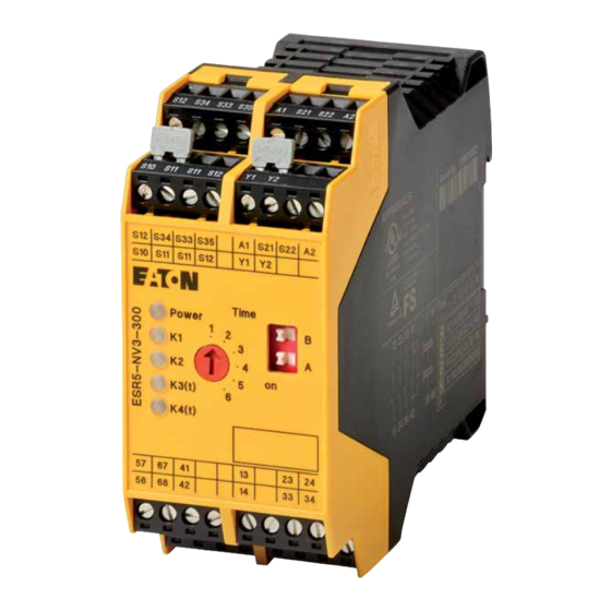
- Page 1 Manual 12/19 MN049006EN ESR5-NV3-300 Safety relay...
- Page 2 No part of this manual may be reproduced, stored in a retrieval system, or transmit- ted in any form or by any means, electronic, mechanical, photocopying, micro-film- ing, recording, or otherwise, without the prior written permission of Eaton Industries GmbH, Bonn, Germany.
- Page 3 Danger! Dangerous electrical voltage! Before commencing the installation • Disconnect the power supply of the device. • Wherever faults in the automation system may cause damage to persons or property, external measures must • Ensure that devices cannot be accidentally retriggered. be implemented to ensure a safe operating state in the •...
-
Page 5: Table Of Contents
Time diagram for automatic start, two-channel control ....12 Time diagram for manual start, single-channel control ....12 Mounting and removing............13 Wiring..................14 10.1 Signal generator connection versions .......... 14 10.2 Start and feedback circuit connection variants......15 ESR5-NV3-300 12/19 MN049006EN www.eaton.com... - Page 6 Application example - Two-channel safety door monitoring with dropout delayed contacts and manual reset (with cross-circuit detection)............ 21 Attachment - using devices at altitudes greater than 2000 m above sea level ............. 22 Technical data ................23 Glossary ..................26 ESR5-NV3-300 12/19 MN049006EN www.eaton.com...
-
Page 7: About This Manual
0 About This Manual 0 About This Manual This manual applies to the ESR5-NV3-300 safety relay. 0.1 List of revisions The following significant amendments have been introduced since previous issues: Publication Page Keyword modified deleted date 12/19 First edition –... -
Page 8: Abbreviations And Symbols
Warns of the possibility of hazardous situations that could result in serious injury or even death. DANGER Warns of hazardous situations that result in serious injury or death. 0.4.3 Tips → Indicates useful tips. 0.5 Ordering data ESR5-NV3-300 safety relay: Catalog No. 171858 ESR5-NV3-300 12/19 MN049006EN www.eaton.com... -
Page 9: Safety Notes
Risk of damage to equipment due to noise emissions When operating relay modules the operator must meet the requirements for noise emission for electrical and electronic equipment (EN 61000-6-4) on the contact side and, if required, take appropriate measures. ESR5-NV3-300 12/19 MN049006EN www.eaton.com... -
Page 10: Description
2 Description 2 Description Intended Use The ESR5-NV3-300 safety relay is used for emergency stop, safety door, and light grid monitoring. The safety relay interrupts circuits in a safety-related way. Possible signal generators • Emergency stop button • Door locking mechanisms •... -
Page 11: Operating And Indication Elements
Status indicator safety circuit; LED (green) K3(t) Status indicator safety circuit; LED (green) K4(t) Status indicator safety circuit; LED (green) 57/58, 67/68 Delayed enabling current paths 41/42 Signaling current path, undelayed 13/14, 23/24, 33/34 Undelayed enabling current paths ESR5-NV3-300 12/19 MN049006EN www.eaton.com... -
Page 12: Basic Circuit Diagram
Start and feedback circuit Y1/Y2 Feedback circuit S10, S12 Input sensor circuit Output 24 V Output 0 V Input sensor circuit 13/14, 23/24, 33/34 Undelayed enabling current paths 41/42 Signaling current path 57/58, 67/68 Delayed enabling current paths ESR5-NV3-300 12/19 MN049006EN www.eaton.com... -
Page 13: Derating
Perform the actual calculation and offset the derating curve for the device used according to the technical data and the “Derating” section. [°C] Figure 4: Example of a suspended derating curve (blue) 27 °C x 0,906 = 24 °C 55 °C x 0,906 = 49 °C ESR5-NV3-300 12/19 MN049006EN www.eaton.com... -
Page 14: Load Curve - Ohmic Load
6 Load curve - ohmic load 6 Load curve - ohmic load 1000 I [A] Figure 5: Relay load curve - ohmic load ESR5-NV3-300 12/19 MN049006EN www.eaton.com... -
Page 15: Function Description
The enabling current paths 57/58 and 67/68 drop out after the set delay time has elapsed (stop category 1). Use the rotary switch and DIP switch on the device to set the delay time in 24 increments from 0.2 s to 300 s. → See also → section 12, “Configuration”, page 17 ESR5-NV3-300 12/19 MN049006EN www.eaton.com... -
Page 16: Function And Time Diagrams
Explanation A1/A2 Power supply S34, S35 Start circuit S10 / S12 / S22 Input sensor circuit 13/14, 23/24, 33/34 Undelayed enabling current paths 57/58, 67/68 Delayed enabling current paths 41/42 Signaling current path, undelayed Delay time ESR5-NV3-300 12/19 MN049006EN www.eaton.com... -
Page 17: Mounting And Removing
9 Mounting and removing 9 Mounting and removing ▶ Mount the device on a 35 mm DIN rail according to EN 60715. ▶ To remove the device, use a screwdriver to release the snap-on foot. Figure 8: Mounting and removing ESR5-NV3-300 12/19 MN049006EN www.eaton.com... -
Page 18: Wiring
10.1 Signal generator connection versions ▶ Connect suitable signal generators to S10/S11/S12 and S21/S22. ① ② ③ Figure 10:Signal generator connection versions a Two-channel connection with cross-circuit monitoring b Two-channel connection without cross-circuit monitoring c Single-channel connection ESR5-NV3-300 12/19 MN049006EN www.eaton.com... -
Page 19: Start And Feedback Circuit Connection Variants
S34 or S33/S35 to monitor external contactors or extension devices with force-guided contacts. ① ② ③ ④ Figure 11:Start and feedback circuit connection variants a Automatic start b Automatic start with monitored contact extension c Manual, monitored start with monitored contact extension d Manual, monitored start ESR5-NV3-300 12/19 MN049006EN www.eaton.com... -
Page 20: Startup
Manual, monitored start ▶ Press the reset button. → The enabling current paths 13/14, 23/24, 33/34, 57/58, 67/68 close. → The s ignaling current path 41/42 opens. → The K1, K2, K3(t) and K4(t) LEDs light up. ESR5-NV3-300 12/19 MN049006EN www.eaton.com... -
Page 21: Configuration
Figure 12: Configuration of the delay time (in seconds) WARNING Danger due to incorrect setting! An incorrect configuration can result in dangerous machine or system states. Check the configuration before starting up for the first time. ESR5-NV3-300 12/19 MN049006EN www.eaton.com... -
Page 22: Protection Against Manipulation
Once the time has been set, the rotary switch and the DIP switch can be protected against manipulation by covering with the label provided. Operate the safety relay in a locked control cabinet to protect the configura- tion against manipulation. Figure 13: Applying the label ESR5-NV3-300 12/19 MN049006EN www.eaton.com... -
Page 23: Calculating The Power Dissipation
B ² L1 ² L2 ² Ln ² = U / (U ) + (I + I + … + I ) x 200 m Total Power dissipation in mW Applied operating voltage Nominal input voltage Input current Number of enabling current paths used Contact load current ESR5-NV3-300 12/19 MN049006EN www.eaton.com... -
Page 24: Diagnostics
To do this, request the safety function once via the basic device by pressing the emergency stop button, for example. Check whether the safety function is executed correctly by then switching the basic device and thereby also the contact exten- sion on again. ESR5-NV3-300 12/19 MN049006EN www.eaton.com... -
Page 25: Application Example - Two-Channel Safety Door Monitoring With Dropout Delayed Contacts And Manual Reset (With Cross-Circuit Detection)
Safety level drive 2 PL d (EN ISO 13849-1) and SIL 2 (EN 62061) (L1) Drive 1 Drive 2 Safety door open closed S10 S11 S21 S22 (GND) ESR5-NV3-300 S33 S34 S35 Reset Figure 14: Two-channel safety door monitoring with dropout delayed contacts and manual reset ESR5-NV3-300 12/19 MN049006EN www.eaton.com... -
Page 26: Attachment - Using Devices At Altitudes Greater Than 2000 M Above Sea Level
16 Attachment - using devices at altitudes greater than 2000 m above sea level → The following section describes the special conditions for using ESR5-NV3-300 devices at altitudes greater than 2000 m above sea level. Observe the relevant device-specific data (technical data, derating, etc.) according to the product documentation for the individual device. -
Page 27: Technical Data
Maximum inrush current 20 A (Δt ≦ 100 ms, undelayed contacts) 8 A (delayed contacts) Inrush current, minimum 10 mA Sq. Total current 55 A = (I + (I + … + (I (see derating curve, → Figure 5, page 9) ESR5-NV3-300 12/19 MN049006EN www.eaton.com... - Page 28 22.5 x 99 x 114.5 mm Connection data Conductor cross section, solid 0.2 mm - 2.5 mm Conductor cross section, stranded 0.2 mm - 2.5 mm Conductor cross section AWG/kcmil 24 - 12 Stripping length 7 mm Screw thread ESR5-NV3-300 12/19 MN049006EN www.eaton.com...
- Page 29 For applications in PL e, the required demand rate for the safety function is once per month. Calculation basis: 230000 (at 3 A AC-15) Cycles 8760 per year Safety parameters for EN 62061 SILCL 3 (for delayed contacts SILCL 2) ESR5-NV3-300 12/19 MN049006EN www.eaton.com...
-
Page 30: Glossary
Classification of the ability of safety functions to meet a safety demand Safety integrity level SILCL SIL claim limit SRCF Safety-related control function SRECS Safety-related electrical control system (Safety-related electrical, electronic, and programmable electronic control system) Safety-related part SRP/CS Safety-related parts of control system ESR5-NV3-300 12/19 MN049006EN www.eaton.com...
Need help?
Do you have a question about the ESR5-NV3-300 and is the answer not in the manual?
Questions and answers