Table of Contents
Advertisement
Quick Links
Advertisement
Table of Contents

Subscribe to Our Youtube Channel
Related Manuals for Nord Drivesystems SK CU4-DEV


Summary of Contents for Nord Drivesystems SK CU4-DEV
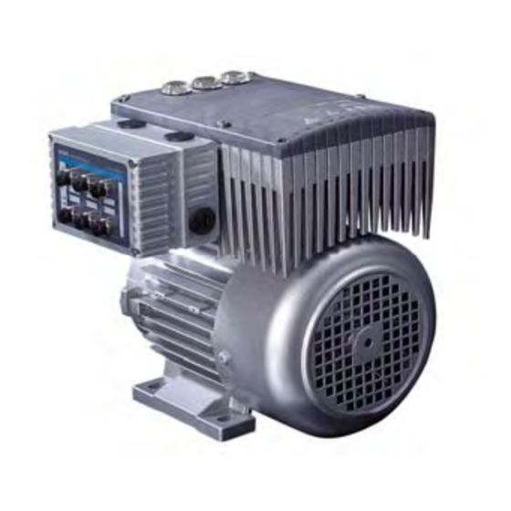
- Page 1 Intelligent Drivesystems, Worldwide Services SUPPLEMENTARY MANUAL BU 0280 GB DEVICENET FOR FREQUENCY INVERTER NORDAC SK 200E Illustration of devices with options BU 0280 GB Getriebebau NORD GmbH & Co. KG Rudolf-Diesel-Straße 1 D-22941 Bargteheide Tel.: +49 45 32 - 40 10 Fax: +49 45 32 - 40 12 53...
- Page 2 Supplementary Manual DeviceNet for NORDAC SK 200E BU 0280 GB...
- Page 3 Supplementary Manual DeviceNet for NORDAC SK 200E Safety information NORDAC frequency inverter Safety and operating instructions for drive power converters (as per: Low voltage guideline 73/23/EEC ) 1. General 4. Installation During operation, drive power converters may have, depending on The installation and cooling of the equipment must be their protection class, live, bare, moving or rotating parts or hot implemented...
- Page 4 About this document Documentation Designation: BU 0280 GB Part. No.: 607 28 01 Device series: DeviceNet for SK 200E Device types: SK CU4-DEV SK TU4-DEV(-C) with SK TI4-TU-BUS SK TU4-DEV-M12(-C) with SK TI4-TU-BUS Version list Designation of previous issues Software Comments...
- Page 5 Supplementary Manual DeviceNet for NORDAC SK 200E About this document Intended use of the frequency inverter Compliance with the operating instructions is the requirement for error-free operation and the fulfilment of any warranty claims. You must first read these operating instructions before working with the device! These operating instructions contain important information about service.
-
Page 6: Table Of Contents
2 ASSEMBLY AND INSTALLATION ..................13 2.1 Installation and assembly .................. 13 2.1.1 Features of DeviceNet modules ................15 2.1.2 Installation of the Customer Unit SK CU4-DEV ............16 2.1.3 Installing the SK TU4-DEV-… Technology Unit ............17 2.2 Electrical connection ..................19 2.2.1 Cable glands ...................... - Page 7 Table of Contents 5 PARAMETERISATION ......................47 5.1 Parameterising the SK 200E frequency inverter ..........47 5.1.1 Basic parameters (P100) ..................47 5.1.2 Control terminal parameters (P400) ................ 48 5.1.3 Supplementary parameter (P500) ................50 5.1.4 Information parameters (P700) ................54 5.2 Parameterisation of the bus module (SK CU4-…...
-
Page 8: General Information
Supplementary Manual DeviceNet for NORDAC SK 200E General information Various technology options are available for Getriebebau Nord frequency inverters. General information regarding these can be found in the relevant main manual of the frequency inverter series (e.g. Manual BU0200 for the SK 200E frequency inverter series). Further information concerning special technology options (e.g. -
Page 9: Overview
Interface (RS232/RS485) for parameter access by means of the SK CSX-3H or SK PAR-3H manual control unit or NordCon software via RJ12 connector (Except for SK CU4-DEV. Here parameter access via the SK 200E frequency inverter is possible) ... -
Page 10: Certifications
Supplementary Manual DeviceNet for NORDAC SK 200E Available accessories: SK TI4-TU-BUS(-C) (bus connection unit, required for SK TU4…) SK TIE4-WMK-TU, wall-mounting kit TU4 M12 round plug connector Matching RJ12 to SUB-D9 adapter cable to connection to a PC ParameterBox: SK CSX-3H, SimpleBox, 4 digit 7 segment LED display ParameterBox: SK PAR-3H, ParameterBox, plain text LCD display 1.4 Certifications 1.4.1... -
Page 11: Type Code / Optional Bus Modules
1 General information 1.5 Type code / Optional BUS modules BUS = Bus module or I/O extension SK TU4-DEV (-C-M12-WMK-TU) Wall mounting kit: for external technology units TU4 M12 system connectors: only TU4, alternative to terminals IP protection class: Standard = IP55, C = “coated”... -
Page 12: Version With Protection Class Ip55 / Ip66
Supplementary Manual DeviceNet for NORDAC SK 200E 1.6 Version with protection class IP55 / IP66 NORDAC SK 200E frequency inverters and the external additional modules are available in all sizes and powers in the protection classes IP55 (standard) or IP66 (optional). The protection class IP66 must always be included in the order when ordering! There are no restrictions or differences to the scope of functions in either protection class. -
Page 13: Assembly And Installation
2 Assembly and installation Assembly and installation 2.1 Installation and assembly Internal and external technology modules designed for NORDAC SK 200E series are available for DeviceNet. Except for the number of digital inputs and outputs, the functionalities of the various DeviceNet modules are identical. - Page 14 Supplementary Manual DeviceNet for NORDAC SK 200E The external technology modules (Technology Unit, SK TU4-...) – designated as the technology unit – are externally attached to the SK 200E connection unit and are therefore easy to access. Mounting of the SK TU4- ...
-
Page 15: Features Of Devicenet Modules
Data Baud rate: up to 500 kBaud Connection: DeviceNet module 16-terminal screw terminal bar SK CU4-DEV Part No. 275271002 (IP20) This option enables control of the NORDAC SK 2x digital inputs: 200E via DeviceNet. Low: 0-5V, High: 11-30V This option is integrated into the connection unit of the frequency inverter. -
Page 16: Installation Of The Customer Unit Sk Cu4-Dev
The pre-assembled cables for connection to the frequency inverter (SK 200E) are also included in the bag enclosed with the customer unit. Connections are made according to the following table: Internal customer unit SK CU4-DEV Bag enclosed with internal customer unit SK TI4-… with integrated customer unit SK CU4-DEV Function Terminal label Cable colour... -
Page 17: Installing The Sk Tu4-Dev
2 Assembly and installation 2.1.3 Installing the SK TU4-DEV-… Technology Unit WARNING Installation must be carried out by qualified personnel only, paying particular attention to safety and warning instructions. Modules must not be installed or removed unless the device is free of voltage. The slots may only be used for the applicable modules. - Page 18 Supplementary Manual DeviceNet for NORDAC SK 200E 2.1.3.3 Mounting the SK T14-TU-BUS on the SK 200E The screw fittings and seals required for installation are enclosed with the modules or are fitted to the intended locations. Mounting of the technology unit on the SK 200E must be carried out as follows: 1.
-
Page 19: Electrical Connection
2 Assembly and installation 2.2 Electrical connection WARNING THE DEVICES MUST BE EARTHED. Safe operation of the devices presupposes that qualified personnel install and commission it in compliance with the instructions provided in these operating instructions. In particular, the general and regional mounting and safety regulations for work on high voltage systems (e.g. -
Page 20: Control Connections
Supplementary Manual DeviceNet for NORDAC SK 200E 2.2.2 Control connections The DeviceNet modules must be provided with one or two 24V DC (±20%, total current consumption 100mA) control voltages. Wire end sleeves must be used for flexible cables. Designation Data 0.14 …... - Page 21 2 Assembly and installation 2.2.2.1 Control connections for SK CU4-DEV The terminal bar of the customer unit SK CU4-DEV is divided into two potential levels. Sys+ System bus connection Sys- from the SK 200E Potential level: Systembus Potential level: DeviceNet...
- Page 22 Supplementary Manual DeviceNet for NORDAC SK 200E Control connection details Terminal/ Function Data Description / wiring suggestion Parameter Designation [factory setting] External 24V supply 24VDC ±20% External supply voltage of the ≈ 50mA , reverse polarity technology unit and supply of the Reference potential digital inputs (DIN1 and DIN2) protected...
- Page 23 2 Assembly and installation 2.2.2.2 Control connections for SK TU4-DEV(-…) The double spring-loaded terminal bar of the technology unit is colour coded, and therefore indicates the three different potential levels. A separate voltage source can be used to supply the DOs. However, by bridging the 24V o and GND o to one of the terminals of the system bus level 24V and GND it is possible to implement the supply of the DOs.
- Page 24 Supplementary Manual DeviceNet for NORDAC SK 200E Control connection details Terminal/ Function Data Description / wiring suggestion Parameter [factory setting] Designation 24V Bus External 24V supply 24VDC -/+20% Voltage supply at DeviceNet bus ≤ 50 mA , reverse polarity potential protected DVN + DeviceNet Bus +...
- Page 25 2 Assembly and installation Terminal/ Function Data Description / wiring suggestion Parameter [factory setting] Designation DIN2 Digital input 2 Low 0V ... 5V High 15V ... 30V P174 [I/O DeviceNet DIN2] = 8.1k Each digital input has a reaction time of 1ms.
-
Page 26: Configuration
Supplementary Manual DeviceNet for NORDAC SK 200E 2.2.3 Configuration The configuration for all DeviceNet module versions is identical. All necessary settings are made using the hardware via a DIP switch element (3+8 part switching block). Customer UnitSK CU4-DEV Technology unitSK TU4-DEV BUS termination Baud rate and addressing DIP switch 3 + 8 part... - Page 27 2 Assembly and installation Configuration example A DeviceNet subscriber SK TU4-DEV is connected to an SK 200E series frequency inverter via a BUS connection unit SK TI4-TU-BUS. The field bus address (DeviceNet address) should be “14” and a baud rate of 250kBaud should be selected.
-
Page 28: Displays And Diagnosis
LEDs. PC-based communication or the connection of a parameterisation unit is possible via an RS232 interface (RJ12 diagnostic socket). RJ12 LEDs Potentiometers DeviceNet Module SK CU4-DEV DeviceNet Module unit SK TU4-DEV-M12 with Frequency inverter SK 200E viewing window (transparent screw-on cover) for RJ12 Status LEDs... - Page 29 3 Displays and diagnosis 3.1.1.2 Customer Unit SK CU4-DEV LEDs MS and NS The dual colour LEDs MS (Module Status) and NS (Network Status) indicate the status of the DeviceNet communication. LEDs DS and DE The dual colour LEDs DS (Device State) and DE (Device Error) indicate the status of the module and the status of the system bus.
-
Page 30: Signal Status Leds
Supplementary Manual DeviceNet for NORDAC SK 200E 3.1.2 Signal status LEDs This manual only describes the LED signal statuses of the DeviceNet modules. Information for the frequency inverter LEDs (SK 200E) can be found in the relevant manual (BU0200). 3.1.2.1 Module-specific displays The status of the technology unit or the system bus is indicated by the LEDs DS and DE . - Page 31 3 Displays and diagnosis 3.1.2.2 DeviceNet displays The status of the DeviceNet module is indicated by the LEDs MS and NS . LED (dual) Significance Slow flashing = 2Hz (0.5s cycle) M odule S tatus No voltage supply ON (green) Normal operation, cyclic exchange of data via DeviceNet Flashing 0.5s Module in standby mode, no connection to one or more FIs.
- Page 32 The status of additional digital inputs and outputs on the BUS module is indicated by corresponding LEDs (except for SK TU4-DEV(-C)). I/O Channel Status display Significance Customer Unit SK CU4-DEV LED (green) Digital input 1 High potential on terminal C1 Low potential on terminal C1...
-
Page 33: Rj12 Diagnostic Socket
Although the customer unit SK CU4-DEV does not have an RJ12 connection, it can be accessed from any other subscriber (frequency inverter) on the same system bus. - Page 34 Supplementary Manual DeviceNet for NORDAC SK 200E Alternatively, diagnosis can be performed via a Windows PC with the aid of NORD CON software (available free of charge from ). The necessary connection cable ( RJ12 - SUB D9 ) is available from www.nord.com Getriebebau Nord GmbH as part number 278910240 .
-
Page 35: Commissioning
4 Commissioning Commissioning The DeviceNet module is a slave with “Group 2 Only Server” properties. Devices of this type can set up the following pre-defined connections: Explicit Request/Response Message (Parameter Transfer) Several static I/O messages (fragmented) Polled I/O connection ... -
Page 36: Devicenet Process Data
Supplementary Manual DeviceNet for NORDAC SK 200E 4.2 DeviceNet process data 4.2.1 I/O messages The assembly object in the DeviceNet module is static. However, it is possible to set various data lengths and profiles in the assembly object via the parameters P160 to P165. The parameters are adopted by the bus modules when the I/O message connection is set up. -
Page 37: Interpretation Of Data In The Assembly Object
4 Commissioning 4.2.2 Interpretation of data in the Assembly Object In the EDS file it is assumed that there is only one FI, or that all FIs have the same setting. This must also be represented by the ODVA. The following official table results from this. Otherwise, all possible or meaningful combinations must be recorded. -
Page 38: Explanation Of The I/O Assembly Data For The Ac Drive Profile
Supplementary Manual DeviceNet for NORDAC SK 200E 4.2.3 Explanation of the I/O Assembly Data for the AC Drive Profile Instance Byte Bit7 Bit 6 Bit 5 Bit 4 Bit 3 Bit 2 Bit 1 Bit 0 Fault Reset Run Fwd Speed setpoint (Low byte) Speed setpoint (High byte) NetRef... -
Page 39: Explanation Of The I/O Assembly Data For The Nord-Ac Profile
4 Commissioning Ref From Net The setpoint for the FI comes via DeviceNet. Only the status of “Netref” is imaged in the control word. The parameters P509 & P510 are not queried. At Ref The FI has attained the setpoint speed 4.2.4 Explanation of the I/O Assembly Data for the NORD-AC Profile Instance... -
Page 40: Generation Of Variable Data Lengths In Instance 120/130
Supplementary Manual DeviceNet for NORDAC SK 200E 4.2.5 Generation of variable data lengths in Instance 120/130 If parameter P160 is set to 0, the structure of the Instance can be freely defined via parameters P161 to P165. The length of the output and input data does not need to be identical. Para Index [0] Index [1]... -
Page 41: Devicenet Objects
4 Commissioning 4.3 DeviceNet objects 4.3.1 Class 1 – Identity Object Inst. Attr. Access Name Type Description Vendor ID UINT Manufacturer identification number Device type UINT Product type Product code UINT Identification of device Revision STRUCT Software version USINT Number of main version USINT Number of ancillary version Status... -
Page 42: Class 4 - Assembly Object
Supplementary Manual DeviceNet for NORDAC SK 200E Baud Rate Switch BOOL TRUE = If there has been a change to the baud Changed rate switches since the last reset or power up. MAC ID Switch USINT Current ID setting on the DIP switch Value Baud Rate USINT... -
Page 43: Class 5 - Devicenet Connection Object
4 Commissioning 4.3.4 Class 5 – DeviceNet Connection Object The settings of the current connection can be read out via this object. The following instances are supported: Instance 1 = Explicit message Instance 2 = Polling Instance 3 = Bit Strobe Instance 4 = COS/Cyclic Attr. -
Page 44: Class 41 - Control Supervisor Object
Supplementary Manual DeviceNet for NORDAC SK 200E 4.3.6 Class 41 – Control Supervisor Object Attr. Access Name Type Description Starts / stops the motor clockwise direction Run Fwd BOOL Starts / stops the motor anticlockwise direction Run Rev BOOL NetCtrl BOOL... -
Page 45: Class 42 - Ac- Drive Object
4 Commissioning 4.3.7 Class 42 – AC- Drive Object Attr. Access Name Type Description AtReference BOOL Actual value corresponds to the setpoint Get/Set NetRef BOOL Setpoints sent via DeviceNet are enabled. DriveMode USINT This parameter is always 0 (specific to vendor). The drive mode can be obtained via FI parameter P509. -
Page 46: Class 100 To 181 - Access To Fi And Bus Module Parameters
Supplementary Manual DeviceNet for NORDAC SK 200E 4.3.9 Class 100 to 181 – Access to FI and bus module parameters All parameters of the bus module and the FIs connected to the bus module can be accessed via the DeviceNet. The FIs connected to bus module can be accessed via various Class ranges. See following table. DeviceNet Class Accessed device FI Offset... -
Page 47: Parameterisation
5 Parameterisation Parameterisation In order to enable communication via DeviceNet, the frequency inverter and the DeviceNet technology unit must be parameterised accordingly. With the DeviceNet protocol, the inverter parameters are mapped in the range 100 to 109: Class = 100 + parameter number / 100 Attribute = Parameter number % 100 Instance = SubIndex + 1 Parameter number = (Class -100) * 100 + Attribute... -
Page 48: Control Terminal Parameters (P400)
Supplementary Manual DeviceNet for NORDAC SK 200E 5.1.2 Control terminal parameters (P400) Parameter Parameter Setting value / Description / Note Device Supervisor {Factory setting} P420 … [-01] Digital inputs 1 to 4 … [-04] 0 ... 72 In the SK 200E, up to 4 freely programmable digital inputs are available. The only restriction is with the versions SK 215E and SK 235E. - Page 49 5 Parameterisation Parameter Parameter Setting value / Description / Note Device Supervisor {Factory setting} P481 ... [-01] Function Bus I/O Out bits ... [-10] 0 ... 39 The bus I/O Out bits are perceived as multi-function relay outputs. They can be set to the same functions (P434).
-
Page 50: Supplementary Parameter (P500)
Supplementary Manual DeviceNet for NORDAC SK 200E 5.1.3 Supplementary parameter (P500) Parameter Parameter Setting value / Description / Note Device Supervisor {Factory setting} P509 Control word source 0 ... 4 Selection of the interface via which the FI is controlled. 0 = Control terminals or keyboard control ** with the SimpleBox (if (P510)=0), the { 0 } ParameterBox or via BUS I/O Bits. - Page 51 5 Parameterisation Parameter Parameter Setting value / Description / Note Device Supervisor {Factory setting} P515 ... [-01] CAN address (system bus) … ... [-03] 0 ... 255 dec Setting of the system bus address. { all 32 dec} … [-01] = Receive address for system bus or { all 20 hex} …...
- Page 52 Supplementary Manual DeviceNet for NORDAC SK 200E Parameter Parameter Setting value / Description / Note Device Supervisor {Factory setting} P546 … [-01] Function Bus setpoint 1 ... 3 … [-03] 0 ... 24 In this parameter, a function is allocated to the output setpoint during bus actuation. { [-01] = 01 } NOTE: For further details, please refer to the description for P400.
- Page 53 5 Parameterisation Parameter Parameter Setting value / Description / Note Device Supervisor {Factory setting} P552 … [-01] System bus master cycle time … [-02] 0 / 0.1 … 100.0 ms In this parameter, the cycle time for the system bus master mode and the CAN open encoder is set (see P503/514/515): { 0 } …...
-
Page 54: Information Parameters (P700)
Supplementary Manual DeviceNet for NORDAC SK 200E 5.1.4 Information parameters (P700) Parameter Parameter Setting value / Description / Note Device Supervisor {Factory setting} P700 Current error 0.0 ... 21.4 Current error present. Further details are described in the frequency inverter manual (BU0200). SimpleBox: Descriptions of the individual error numbers can be found in the point Error messages. - Page 55 5 Parameterisation Parameter Parameter Setting value / Description / Note Device Supervisor {Factory setting} P741 ... [-01] Process data bus Out ... [-10] 0000 ... FFFF (hex) This parameter provides information about the actual status word and the actual values that are transferred via the bus systems.
-
Page 56: Parameterisation Of The Bus Module (Sk Cu4
Supplementary Manual DeviceNet for NORDAC SK 200E 5.2 Parameterisation of the bus module (SK CU4-… or SK TU4-…) The following parameters relate to the bus modules. 5.2.1 BUS module standard parameters (P150) Parameter Parameter Setting value / Description / Note Device Supervisor {Factory setting}... - Page 57 5 Parameterisation Parameter Parameter Setting value / Description / Note Device Supervisor {Factory setting} P161 ... [-01] Config. process data for the bus module ... [-02] 0 ... 1 [-01] = Inputs [-02] = Outputs { 0 } Possible values which can be set: 0 = Module does not transmit 1 = Data length 1 Byte P162...
- Page 58 Supplementary Manual DeviceNet for NORDAC SK 200E Parameter Parameter Setting value / Description / Note Device Supervisor {Factory setting} P164 [-01] Configuration of FI 3 process data [-02] ... [-03] 0 ... 8 [-01] = Status values [-02] = Control values { 0 } Possible values which can be set: 0 = FI does not exist...
-
Page 59: Bus Module Information Parameters, General (P170)
5 Parameterisation 5.2.3 BUS module information parameters, general (P170) Parameter Parameter Setting value / Description / Note Device Supervisor {Factory setting} P170 Current error ... [-01] ... [-02] 0 ... 9999 Current errror. Further details in Section 0 “Error Messages”. …... - Page 60 Supplementary Manual DeviceNet for NORDAC SK 200E Parameter Parameter Setting value / Description / Note Device Supervisor {Factory setting} P173 Module status 0 ... FFFF (hex) Possible values: Bit 0 = Bus status “Online / Not connected” { 0000 } Bit 1 = Bus status “Online / Connected”...
- Page 61 5 Parameterisation Parameter Parameter Setting value / Description / Note Device Supervisor {Factory setting} P176 ... [-01] Process data bus In ... [-17] -32768 ... 32767 Bus data received from DeviceNet master { 0 } … [-01] = Bus module outputs …...
-
Page 62: Module Information Parameters Specific To The Bus (P180)
Supplementary Manual DeviceNet for NORDAC SK 200E 5.2.4 Module information parameters specific to the bus (P180) Parameter Parameter Setting value / Description / Note Device Supervisor {Factory setting} P180 DeviceNet address: 0 ... 63 Each module transmitting on the bus must be allocated a unique address. After the new setting of addresses, all the devices on this bus must be restarted by switching the power supply off { 0 } and on again. -
Page 63: Error Monitoring And Error Messages
6 Error monitoring and error messages Error monitoring and error messages 6.1 Error monitoring The majority of bus module and frequency inverter functions and operating data are continuously monitored and simultaneously compared with limiting values. If a deviation is detected, the bus module or inverter reacts with a warning or an error message. -
Page 64: Error Messages
Supplementary Manual DeviceNet for NORDAC SK 200E 6.2 Error messages 6.2.1 Table of possible error messages (caused by the bus) in the frequency inverter The following error messages concern bus-related messages which are indicated on the frequency inverter. A complete list of error messages for the frequency inverter (SK 200E) can be found in the relevant manual (BU0200). -
Page 65: Table Of Possible Error Messages In The Bus Module
6 Error monitoring and error messages 6.2.2 Table of possible error messages in the bus module The following error messages concern bus-related messages, which are indicated on the DeviceNet module (SK CU4DEV or SK TU4DEV(- … )). Display Fault Cause in the SimpleBox Text in the ParameterBox Remedy... -
Page 66: Devicenet Data Transmission
Supplementary Manual DeviceNet for NORDAC SK 200E DeviceNet data transmission 7.1 Structure of reference data This section describes the cyclic data traffic between the bus master and the frequency inverter. The reference data is divided into two sections: PKW section (Parameter Code Value (parameterisation level)) ... -
Page 67: Nordac Profile
7 DeviceNet data transmission 7.2 NORDAC profile 7.2.1 Control word (STW) The control word (STW) is the first word transferred to the frequency inverter in the process data section in an order telegram. PZD1 PZD2 PZD3 PZD4 SW2/3 SW2/3 Meaning of the individual bits: Value Significance Comments... -
Page 68: Status Word (Zsw)
Supplementary Manual DeviceNet for NORDAC SK 200E 7.2.2 Status word (ZSW) The status word (ZSW) is the first word transferred to the frequency inverter in the process data section of a response telegram. PZD1 PZD2 PZD3 PZD4 IW2/3 IW2/3 Meaning of the individual bits: Value Significance Comments... -
Page 69: Setpoint And Actual Values
7 DeviceNet data transmission 7.2.3 Setpoint and actual values 7.2.3.1 Setpoint 1 (SW1) The function of the first setpoint is set in the parameter "Function bus setpoint 1" (SK 200E: (P546[01]) or SK 500E: (P546)) (see relevant frequency inverter manual). In the order telegram, setpoint 1 follows immediately after the control word. - Page 70 Supplementary Manual DeviceNet for NORDAC SK 200E The definition in the frequency inverter can then, for example, be made via the parameters: PZD3: “Bus function setpoint 2" (SK 200E: (P546[02]) or SK 500E (P547)) and PZD4: “Bus function setpoint 3" (SK 200E: (P546[03]) or SK 500E (P548)) Example If a position setpoint is to be transferred (Prerequisite: posicon inverter functionality) this can be performed either as a 16 bit or 32 bit value.
-
Page 71: The Status Machine
7 DeviceNet data transmission PZD3: “Bus function Actual value 2" (SK 200E: (P543[02]) or SK 500E (P544)) and PZD4: “Bus function Actual value 3" (SK 200E: (P543[03]) or SK 500E (P545)) 7.2.4 The status machine The frequency inverter passes through a status machine“. The changes between various states are triggered by the respective control commands in the process data control word. - Page 72 Supplementary Manual DeviceNet for NORDAC SK 200E Internal status machine Sw itching on the inverter Bit2 = 0: Emergency stop Not on standby Emergency stop active Bit1 = 0: Disable voltage Loading relay applied f = 0 reached v Bit2 = 0: Emergency stop (emergency stop complete) Sw itch-on...
-
Page 73: Additional Information
8 Additional information Additional information 8.1 System bus With NORDAC inverter technology, units or modules communicate via a dedicated system bus. With the launch of the SK 200E frequency inverter series and the associated components SK CU4-... and SK TU4-... functions and interfaces were implemented in this system bus, which enable the user to make appropriate adaptations. -
Page 74: Index
Supplementary Manual DeviceNet for NORDAC SK 200E Index Abbreviations used: Bus error (fault) Module Bus ready BUS state (status) Customer Unit (customer interface - internal technology unit) D, DI, DIN Digital IN DEVICE error (fault) DO, DOUT Digital OUT Decentralised peripheral DEVICE state (status) DeviceNet Electronic data sheet (eds file) -
Page 75: Keyword Index
IP protection class .... 9, 11, 12 Connection ......... 19 TimeOut ........35 Control connections for Type code ........11 SK CU4-DEV ......21 LED ........28, 30 Control terminal parameters ..48 Load factory setting ....56 Control word ....... 67 USS Time Out ...... -
Page 76: Representatives / Branches
Fax: +55-11-6402 88 30 info@nord-ca.com info@nord-br.com India Mexico Indonesia NORD Drivesystems Pvt. Ltd. NORD DRIVE SYSTEMS SA DE CV PT NORD Indonesia Mexico Regional Office 282/ 2, 283/2, Plot No. 15 Jln. Raya Serpong KM7, Av. Lázaro Cárdenas 1007 Pte. - Page 77 Fax: +47-64-905 585 info@nord-it.com info@nord-nl.com info@nord-no.com Portugal Poland Russian Federation NORD Drivesystems PTP, Lda. OOO NORD PRIVODY NORD Napedy Sp. z.o.o. Zona Industial de Oiã, Lote n° 8 Ul. A. Nevsky 9 Ul. Grottgera 30 PT - 3770-059 Oiã Aveiro RU - 191167 St.Petersburg...
- Page 78 NORD offices in Germany Getriebebau NORD GmbH & Co. KG Rudolf- Diesel- Str. 1 22941 Bargteheide Tel.: 04532 / 401 - 0 Fax: 04532 / 401 - 253 info@nord-de.com www.nord.com North branch South branch Getriebebau NORD GmbH & Co. KG Getriebebau NORD GmbH &...
Need help?
Do you have a question about the SK CU4-DEV and is the answer not in the manual?
Questions and answers