Table of Contents
Advertisement
Quick Links
Advertisement
Table of Contents

Subscribe to Our Youtube Channel
Related Manuals for Nord Drivesystems SK 750E-751-323-A


Summary of Contents for Nord Drivesystems SK 750E-751-323-A
- Page 1 Для заказов : +7(499)707-11-20 Email: i@sp-t.ru 8-800-511-65-88 (Бесплатно по РФ) MANUAL NORDAC SK 750E Frequency Inverter SK 750E-551-323-A (-W) ... SK 750E-112-323-A (-W) (5.5kW … 11kW, 3~ 230V) SK 750E-551-340-A (-W) ... SK 750E-222-340-A (-W) (5.5kW … 22kW, 3~ 400V) BU 0750 GB...
- Page 2 NORDAC SK 750E Handbuch Safety instructions NORDAC SK 750E Frequency Inverter Instructions for the safety and use of variable frequency inverters (as provided in the 73/23/EEC low-voltage directive) 1. General 4. Installation Depending on their type of enclosure, variable frequency invert- The devices must be installed and cooled as directed in the rele- ers may have live, bare, in some cases even moving or rotating vant documentation.
- Page 3 NORDAC SK 750E Manual Regarding the present document Documentation Designation/Name/Title: BU 0750 GB Part no.: 607 75 02 Device series: SK 750E List of versions/updates Titles of previous editions Last up- Remarks date s.w. BU 0750 GB, December 2004 V 3.1 R1 First edition, based on BU 0700 GB BU 0750 GB, December 2005 V 3.1 R2...
-
Page 4: Table Of Contents
NORDAC SK 750E Handbuch 1 GENERAL .............................6 1.1 Essentials ......................... 6 1.2 Delivery ........................6 1.3 Scope of delivery ...................... 7 1.4 Safety and installation instructions ................8 1.5 Licenses and approvals .................... 9 1.5.1 UL and cUL approvals ..................9 1.5.2 European EMC directive................... - Page 5 Table of contentsl 3.4 Overview of special extensions ................46 3.4.1 How to install the special extension units ............47 3.4.2 How to remove the special extension module..........48 3.4.3 Encoder I/O special extension................ 49 3.4.4 PosiCon I/O special extension ............... 50 3.5 Control terminals of customer I/Os .................
-
Page 6: General
NORDAC SK 750E manual General Based on the proven SK 700E type series, the NORDAC SK 750E design was specifically adapted to demand- ing industrial environments (up to 60°C, IP54 min.). The devices of this type series are characterized by a high degree of modularity while ensuring optimal control performance. -
Page 7: Scope Of Delivery
1 General 1.3 Scope of delivery Standard package: IP54 type of protection (air cooling) / (IP65 water cooling as a special feature) → kindly specify your choice when ordering! Integrated braking chopper Integrated EMC line filter for limit curve A as per EN55011 Blind cover for the 1 and 2 equipment box (TU) plug-in section... -
Page 8: Safety And Installation Instructions
NORDAC SK 750E manual 1.4 Safety and installation instructions NORDAC SK 750E are operational equipment for use in industrial power plant. That is why touching them may cause, due to the voltages at which they are operated, serious injuries or even death. Only skilled personnel qualified in electrotechnical professions are allowed to perform installation or any other work on the devices provided that these have been previously disconnected from supply. -
Page 9: Licenses And Approvals
1 General Ensure that neither children nor the general public will have access to the device or a chance to CAUTION manipulate it! The device must not be used for any purpose other than the one intended by the manufacture. Unauthorized modifications and the use of replacement parts and attachments which are not sold or recommended by the manufacturer may cause fire, electric shock, and injuries. -
Page 10: Nomenclature / Type Code
NORDAC SK 750E manual 1.6 Nomenclature / Type code The structure of the nomenclature applicable to the NORDAC SK 750E frequency inverter is identical to the one applicable to the other NORDAC frequency inverters. Accordingly the information contained should be read and used in a comparable fashion. -
Page 11: Types Of Protection Ip54/Ip65
1 General 1.7 Types of protection IP54/IP65 The NORDAC SK 750E frequency inverter is available either with an IP54 type of protection (air cooling) or with type of protection IP65 (water cooling) irrespective of the frame size or - accordingly - the level of per- formance. -
Page 12: Mounting And Installation
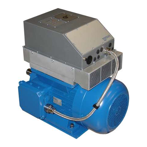
NORDAC SK 750E manual Mounting and installation 2.1 On the motor and close to the motor SK 750E frequency inverters designed for integration are fitted directly to the motor by means of an attachment frame and "mounting feet" so as to represent a functional drive unit. Design for integration: Shown: SK 750E, IP54 design (air-cooled) Optional Technology Unit... -
Page 13: Mounting
2 Mounting and installation 2.2 Mounting NORDAC SK 750E frequency inverters come in different frame sizes according to their power ratings. The place where the device is mounted should be planned with care so that its performance will not be impaired. To protect the devices from overheating, sufficient ventilation must be ensured. -
Page 14: Sk 750E Dimensions
NORDAC SK 750E manual 2.3 SK 750E dimensions Wall mounting kit (optional, Section 2.5) Inverter type L length W width D depth Weight SK 750E-551-323-A … SK 750E-751-323-A 237.5 457.5 220.5 18.0 372 * 165 * 401* 415.5* SK 750E-551-340-A …... -
Page 15: Accessories For Attachment Of The Sk 750E
1. Where frame size 2 is concerned, the wall-mounting kits for the two varieties are different however (see table below). Type For device with designation Part number SK 750E-551-323-A (-W) ... SK 750E-751-323-A (-W) SK WMK-750E-BG1 275219000 SK 750E-551-340-A (-W) ... SK 750E-152-340-A (-W) SK 750E-921-323-A ... SK 750E-112-323-A... -
Page 16: Dimensions Of The Sk 750E With Wall Mounting Kit
NORDAC SK 750E manual 2.5.1 Dimensions of the SK 750E with wall mounting kit Note For the dimensions please read the table in Section 2.2. Fig.: SK 750E with SK WMK-750E-BG1 Technical design subject to change BU 0750 GB... -
Page 17: Mounting The Sk 750E Directly On The Motor
(integrated drive). Three different attachment frames are available al- lowing for mounting the device to differently sized motors (132, 160, 180MX/LX). Attachment frame for device Piece number SK 750E-551-323-A ... SK 750E-751-323-A Attachm. frame-750E-BG1-IEC132 275218000 SK 750E-551-340-A ... SK 750E-751-340-A Attachm. frame-750E-BG1-IEC160 SK 750E-112-340-A ... -
Page 18: Wiring Instructions
NORDAC SK 750E manual 2.7 Wiring instructions The inverters were designed to be operated in an industrial environment where a high level of industrial inter- ference is to be expected. In general, if installation has been carried out in a workmanlike manner, safe and trouble-free operation is ensured. -
Page 19: Electrical Connection
2 Mounting and installation 2.8 Electrical connection THESE DEVICES MUST BE EARTHED. For the device to work safely and reliably, it must have been installed and put into operation by qualified personnel in a workmanlike manner, with all of the instructions mentioned in the present WARNING Operating Manual being followed as specified. - Page 20 NORDAC SK 750E manual Before the device is connected the following should be ensured: 1. Make sure that the voltage source is supplying the right voltage and is rated for the required current (cf. Section 9, Technical data). Besides see to it that a suitable power switch covering the specified nominal current range is connected between voltage source and frequency inverter.
-
Page 21: Mains Connection (Pe, L1, L2, L3)
2 Mounting and installation 2.9.1 Mains connection (PE, L1, L2, L3) There is no need for special protection on the inverter mains input, but standard line protection (cf. Section 9, Technical data) and a master switch/master contac- tor are recommended anyhow. Note: For this frequency inverter type to be connected to an IT-net only slight modification will be required. -
Page 22: Temperature Sensor (T1, T2)
(SK CU1-...). This subject is dealt with in greater detail in Section 3.3, Overview of the custom interfaces. 2.9.6 Power supply terminals Frame size 1: SK 750E-551-323-A ... SK 750E-751-323-A (5.5 / 7.5kW, 230V) SK 750E-551-340-A ... SK 750E-152-340-A (5.5 … 15kW, 400V) braking... -
Page 23: Control Terminals (Optional)
2 Mounting and installation 2.9.7 Control terminals (optional) The way the control lines are connected essentially depends on the optional modules involved (custom inter- faces / special extensions). The various means and methods are described in Sections 3.3. / 3.4. On this page you will find general specifications and information relating to any custom interface or special ex- tension that may be used. -
Page 24: Cable Clamp Screws
NORDAC SK 750E manual 2.9.8 Cable clamp screws Some of the cable clamp screws used with SK 750E frequency inverters are different for frame sizes 1 and 2. The cable entries for the mains input and for the frequency inverter output where the motor is connected are different (see table below). -
Page 25: Optional Equipment
3 Optional equiment Optional equipment 3.1 Modular subassemblies The NORDAC SK 750E can be upgraded in various convenient ways to adapt it to all kinds of control proc- esses. Features that can be added include modules for display, for control, and for parameterization. Besides, modules for the processing of analogue and digital signals and all commonly used bus systems are available, too. -
Page 26: Overview Of The Technology Units
NORDAC SK 750E manual 3.2 Overview of the Technology Units Technology units are optional subassemblies which are plugged on the inverter. They are used to control or to parameterize the inverter or to read out current operating values. Technology boxes include the Potentiome- terBox and the ControlBox which were designed to increase the convenience of operation of the frequency in- verter, and various bus subassemblies with which frequency inverters can be interfaced with a master control unit. - Page 27 3 Optional equiment Technology Unit T. of prot. Description Data SK TU2-... Profibus module (ext. 24V) Profibus interface SK TU2-PBR-24V IP55 Baud rate: 12 Mbps With this option the NORDAC SK Part no. 275130110 Two 5-pole M12 system connec- 750E can be controlled via the tors Profibus module (ext.
-
Page 28: Assembly Of The Technology Units
NORDAC SK 750E manual 3.2.1 Assembly of the Technology Units The technology units are assembled as follows: 1. Switch off the mains voltage, wait for the period specified. 2. To remove the blind cover, loosen the 6 screws with which it is attached and detach the PE conduc- tor. -
Page 29: Controlbox
3 Optional equiment 3.2.2 ControlBox (SK TU2-CTR, part no.: 275130130) (SK TU2-CTR-C, part no.: 275170130) This optional module was designed as a tool for convenient parameterization and control of the SK 750E frequency inverter and for reading out current op- erating information. - Page 30 NORDAC SK 750E manual Functions of the ControlBox: Operate this button to switch the inverter on. If a start-off frequency has been set (P113), the inverter is now enabled at this frequency. If no start-off frequency setting has been made, the inverter will supply the set minimum frequency (P104) anyway.
- Page 31 3 Optional equiment How to control the frequency inverter with the ControlBox If you want to control the frequency inverter with the ControlBox, do not previously enable the inverter via the control terminals or via a serial interface (P509 = 0). When the "START"...
- Page 32 NORDAC SK 750E manual Parameterisation with the ControlBox The frequency inverter can be parameterised in any of the operating modes. All of the parameters can be modified at any time while control by the frequency inverter keeps going on. Depending on the operating status and the source of enable, switching to the parameterisation mode is achieved in different ways.
- Page 33 3 Optional equiment Menu structure when the ControlBox is used Oper. value display (or P 7 - - P 6 - - ready for operation _ _ _ _ resp.) after power ON P 5 - - P 4 - - P 0 - - P 1 - - P 2 - -...
-
Page 34: Potentiometerbox
NORDAC SK 750E manual 3.2.3 PotentiometerBox (SK TU2-POT, Part no.: 275130060) (SK TU2-POT-C, Part no.: 275170060) The PotentiometerBox can be used to control a variety of functions. Se- lection can be done in parameter P549. An infinitely variable potentiome- ter and a three-stage switch to select clockwise or counterclockwise rota- tion or Stop respectively are integrated in the module as operating ele- ments. -
Page 35: Profibus Module
3 Optional equiment 3.2.5 Profibus module (SK TU2-PBR, part no.: 275130070) (SK TU2-PBR-C, part no.: 275170070) (SK TU2-PBR-24V, part no.: 275130110) (SK TU2-PBR-24V-C, part no.: 275170110) (SK TU2-PBR-KL, part no.: 275130065) (SK TU2-PBR-KL-C, part no.: 275170065) ith the Profibus system, data can be exchanged among a major number of automation devices whatever their description. -
Page 36: Interbus Module
NORDAC SK 750E manual 3.2.7 InterBus module (SK TU2-IBS, part no.: 275130080) (SK TU2-IBS-C, part no.: 275170080) With the InterBus system data can be exchanged among a major number of automation devices whatever their description. In fact stored-program controllers, PC's, operating and monitoring units can all be connected to a single bus up to a total number of 256 and com- municate with one another in serial bit mode. -
Page 37: Upgrading Kit, Sk Tu2 Cover
3 Optional equiment 3.2.9 Upgrading kit, SK TU2 cover (SK TU2 cover for SK 300E BG1/BG2, part no.: 275113050) The NORDAC trio SK 300E upgrading kit is bolted on to the assembly sur- face of SK 300E technology units from above. This kit includes a blind cover whose dimensions are identical with those of the technology unit, an appropriate seal and 6 screws for fixing. -
Page 38: Overview Of The Customer Interfaces
NORDAC SK 750E Manual 3.3 Overview of the customer interfaces Customer interfaces are optional slide-in modules. The expansion slot provided for them is located inside the frequency inverter housing on the left guide rail. After the customer units have been inserted the frequency in- verter will identify them automatically. -
Page 39: How To Assemble The Custom Interfaces
3.3 Overview of the customer interfaces regarding the 5V / 15V power supply units NOTE Some of the customer interfaces and special extension modules have got more voltage sources than one (5V / 15V) which can be used by external devices. The maximum allowable external load current is 300mA. -
Page 40: How To Detach The Custom Interfaces
NORDAC SK 750E Manual 3.3.2 How to detach the custom interfaces 1. Switch off the mains voltage and wait a few minutes as specified. 2. Loosen the 8 screws with which the in- verter cover is attached and remove it. Take care not to disturb the PE connection (see the figure showing the PE connection on the preceding page). -
Page 41: Basic I/O Custom Interface
3.3 Overview of the customer interfaces 3.3.3 Basic I/O custom interface (SK CU1-BSC, part no.: 278200000) The Basic I/O custom interface (Customer Unit) affords a sufficient number of control terminals to handle control jobs of a straightfor- ward kind. With this design it is a favourably priced option suitable for a lot of applications. -
Page 42: Standard I/O Custom Interface
NORDAC SK 750E Manual 3.3.4 Standard I/O custom interface (SK CU1-STD, part no.: 278200020) The Standard I/O custom interface (Customer Unit) affords a num- ber of control terminals sufficient for the majority of applications plus a RS485 interface. One analogue differential input and 4 digital inputs are provided to control the frequency inverter. -
Page 43: Multi I/O Custom Interface
3.3 Overview of the customer interfaces 3.3.5 Multi I/O custom interface (SK CU1-MLT, part no.: 278200010) Maximum enhancement of the SK 750E in terms of digital and analogue signal processing is enabled if the Multi I/O custom inter- face (Customer Unit) is used. It will add 2 analogue and 6 digital inputs to the basic equipment of the inverter. -
Page 44: Multi I/O 20Ma Custom Interface
NORDAC SK 750E Manual 3.3.6 Multi I/O 20mA custom interface (SK CU1-MLT-20mA, part no.: 278200015) Maximum enhancement of the SK 750E in terms of digital and analogue signal processing is enabled if the Multi I/O 20mA cus- tom interface (Customer Unit) is used. It will add 2 analogue and 6 digital inputs to the basic equipment of the inverter. -
Page 45: Bus-Type Customer Interfaces, Sk Cu1-Can-Rj, Sk Cu1-Pbr
3.3 Overview of the customer interfaces 3.3.7 Bus-type customer interfaces, SK CU1-CAN-RJ, SK CU1-PBR (SK CU1-CAN-RJ, part no.: 278200052) (SK CU1-PBR, part no..: 278200030) All bus-type customer interfaces are equipped not only with data ports, but also with conventional digital inputs and out- puts. -
Page 46: Overview Of Special Extensions
NORDAC SK 750E Manual 3.4 Overview of special extensions With any of the special extensions (EX- tension Units) the standard frequency in- verter is turned into a high-precision con- trol device which allows for any of the re- quirements of an application to be taken into account. -
Page 47: How To Install The Special Extension Units
3.5 Terminal assignment 3.4.1 How to install the special extension units 1. Switch off the mains voltage and wait a few minutes as recommended. 2. Loosen the 8 screws with which the device cover is attached and remove it. Take care not to disturb the PE connection. -
Page 48: How To Remove The Special Extension Module
NORDAC SK 750E Manual 3.4.2 How to remove the special extension module 1. Switch off the mains voltage and wait a few min- utes as recommended. 2. Loosen the 8 screws with which the device cover is attached and remove the cover. Keep your eye on the PE connection while you are working. -
Page 49: Encoder I/O Special Extension
3.5 Terminal assignment 3.4.3 Encoder I/O special extension (SK XU1-ENC, part no.: 278200120) The Encoder I/O special EXtension Unit enables connection of an in- cremental encoder with a TTL signal level. In this instance the in- cremental encoder must be fitted directly to the motor shaft. Extending the inverter in this way allows for high-precision speed control from zero speed to twice the nominal speed of the motor. -
Page 50: Posicon I/O Special Extension
NORDAC SK 750E Manual 3.4.4 PosiCon I/O special extension (SK XU1-POS, part no.: 278200130) The Posicon I/O special extension (EXtension Unit) provides a posi- tioning control system designed for integration into the inverter. Based on distance and speed calculations, the loads are moved pre- cisely and dynamically to pre-programmed positions. -
Page 51: Control Terminals Of Customer I/Os
3.5 Terminal assignment 3.5 Control terminals of customer I/Os Name/ Customer intreface / special extension units Function Data assign- Terminal ment MLT 20mA CAN-RJ REL 1.1 X3.1.01 X1.1.01 X2.1.01 X2.1.01 X7.1.01 X6.1.01 REL 1.2 X3.1.02 X1.1.02 X2.1.02 X2.1.02 X7.1.02 X6.1.02 N/O contact REL 2.1 X1.1.03 X2.1.03... - Page 52 NORDAC SK 750E Manual Customer interface / Special extension unit Name/ as- Function Data signment Terminal MLT 20mA CAN-RJ RS485 + X1.4.73 Electrically isolated in- RS485 - X1.4.74 CAN1 H X7.3 USS transmission rate up to 38400 Baud CAN1 L X7.3 CAN transmission rate Serial interface...
-
Page 53: Incremental Encoder Cable Colours And Connection Pin Assignment
3.5 Terminal assignment 3.6 Incremental encoder cable colours and connection pin assignment Incremental encoder cable Assignment with encoder option Assignment with PosiCon option Function SK XU1-ENC SK XU1-POS colours 15 volt supply brown / green X11.1.42 VO +15V X10.2.42 VO +15V 0 volt gnd white / green X11.1.40 GND /0V... -
Page 54: Operation And Display
NORDAC SK 750E Manual Operation and display To operate the SK 750E various solutions are available of which the optimal one can be adopted for any appli- cation situation. For instance if a control unit is to be used on the spot very close to the inverter, the handheld version of the ParameterBox can be connected directly with a M12 connecting plug. -
Page 55: Operating Elements Of Connection Varieties
4 Operation and display 4.1 Operating elements of connection varieties BU 0750 GB Technical design subject to change... -
Page 56: Parameterbox Handheld Type, Sk Par-2H
NORDAC SK 750E Manual 4.2 ParameterBox handheld type, SK PAR-2H (SK PAR-2H, part no.: 278910100) The SK PAR-2H ParameterBox is a compact operating device designed to be con- nected directly to the SK 750E frequency inverter. An appropriate connection cable with a M12 male contact comes with the device. -
Page 57: Parameterbox Panel-Mounting Type, Sk Par-2E
4.3 ParameterBox panel-mounting type, SK PAR-2E 4.3 ParameterBox panel-mounting type, SK PAR-2E (SK PAR-2E, part no.: 278910110) SK PAR-2E ParameterBox is a compact operating unit designed to be mounted on a switchboard panel. The terminals provided inside the box allow for establishing a connection with up to 5 frequency inverters. -
Page 58: Electrical Connection
NORDAC SK 750E Manual 4.3.1 Electrical connection The SK PAR-2E ParameterBox is connected using the screw-type terminal. Number Description Terminals + 4.5V ... 30V with +15V / 60mA 0.14 ... 1.5 mm² P+ (A) RS485 + P- (B) RS485 - Supply voltage The +15V supply voltage for the ParameterBox can normally be drawn from the connected frequency inverter. -
Page 59: Functions Of The Parameterbox
4.4 Functions of the ParameterBox 4.4 Functions of the ParameterBox Selecting the language For the ParameterBox to be adjusted to the language of the respective user some concise instructions are given below on how to achieve conversion. The first time the device is switched on it will request the user to select a language in either German or English. - Page 60 NORDAC SK 750E Manual Display When the ParameterBox has been connected and the mains power switched on on the frequency inverter, an automatic "bus scan" is run enabling the ParameterBox to identify the frequency inverter it is connected to. Accordingly, it will then read out the type of the frequency inverter and its current operating status. 750E 11,0kW/3 POS STD...
- Page 61 4.4 Functions of the ParameterBox How to use the ParameterBox LCD graphics display with background illumination capable of reading out the operating values and parameter display settings of the connected inverters and the parameter settings of the ParameterBox itself. With the SELECTION keys you can page forward and backward among the menu levels and the vari- ous menu items.
- Page 62 NORDAC SK 750E Manual How to control the frequency inverter with the ParameterBox Complete control of the frequency inverter with the ParameterBox (involving speed and phase sequence of the motor) presupposes that the (P509) >Interface< parameter has been set to the function >Control terminals or keyboard<...
- Page 63 4.4 Functions of the ParameterBox Menu structure of the ParameterBox The menus are arranged on different levels each of which has an annular configuration. To go from one level to the next, users will have to press the ENTER key ( ).
- Page 64 NORDAC SK 750E Manual How to set parameters with the ParameterBox To access the mode for parameterisation, the <Parameterisation< menu group is selected on level 1 of the Pa- rameterBox. Operation of the ENTER key ( ) will provide access to the parameter configuration screen of the connected inverter.
- Page 65 4.4 Functions of the ParameterBox Layout of the screen during parameterisation When a parameter setting is changed, the new value will flash until the input is confirmed with the ENTER key ). To make the default setting of the parameter being edited appear in the display, the two VALUE keys ) must be operated at the same time.
-
Page 66: Parameters Of The Parameterbox
NORDAC SK 750E Manual 4.5 Parameters of the ParameterBox To each menu group certain main functions are assigned as shown in the table below: Menu group Main function Display (P10xx): Selecting the operating values and the layout of the display Parameterisation (P11xx): Programming the connected inverter and each of the storage units... - Page 67 4.4 Functions of the ParameterBox < Parameterisation > menu group (P11xx) Parameter Setting value / Description / Note P1101 Selection of the object to be parameterized Any parameter setting performed after a selection has been made will apply to the selected unit. Unit selection From the list displayed only the devices and storage units which have been recognized in the course of bus scanning will be available.
- Page 68 NORDAC SK 750E Manual < Options > menu group (P13xx) Parameter Setting value / Description / Notes Selection of the language in which the ParameterBox is to be operated P1301 Language options: German English French Language Spanish Swedish Dutch P1302 Selection of the ParameterBox operating mode Off-line: Operation mode...
-
Page 69: Table Of Parameterbox Error Messages
4.4 Functions of the ParameterBox 4.6 Table of ParameterBox error messages Cause Display Type of fault Remedy Communication errors Illegal parameter number Parameter value cannot be These error messages are generated as a result of electromagnetic in- changed terference or because the software versions of the network users are not identical. - Page 70 NORDAC SK 750E Manual Cause Display Type of fault Remedy An unknown module has been plugged into the inverter (custom inter- face). Unidentified extension Please check the components inserted into the inverter. stage If in doubt check the software version of both the Pa- rameterBox and the inverter.
- Page 71 4.4 Functions of the ParameterBox Cause Display Type of fault Remedy Warnings Overwrite data? YES Delete data? These warnings draw the operator's attention to modifications which may YES have far-reaching consequences and require additional acknowledge- Shift SW version? ment.
-
Page 72: Data Exchange Via Nord Con
NORDAC SK 750E Manual 4.7 Data exchange via NORD CON The storage elements S1 to S5 of the NORDAC ParameterBox can be managed and filed via the NORD CON control and parameterisation software. For data transmission to be possible, the PC's serial interface (RS232) must be connected with the Parame- terBox via an interface converter (SK IC1-232/485, part no. -
Page 73: Nord Con Software
5 NORD CON Software NORD CON software 5.1 General NORD CON is a PC program designed to control and parameter- ise NORDAC frequency inverters produced by the NORD com- pany. This software can be installed on any computer with a Windows 95, 98, NT, 2000, ME or XP operating system. - Page 74 NORDAC SK 750E Manual Oscilloscope function The function desired for recording can be selected from various optional channel settings. Four chan- nels are available in all with their range of values and time base being scalable. For long-term storage the curves can be saved to memory along with the respective settings and re- trieved again at a later date.
-
Page 75: System Start-Up
6 System start-up System start-up General When power is fed to the inverter it will be ready for operation within moments. In this condition the inverter can be adjusted to the requirements of the application, in other words the parameters of the control process can be defined. -
Page 76: Basic Operation - Condensed Instructions
NORDAC SK 750E Manual 6.2 Basic operation – Condensed instructions ... involving the ControlBox subassembly (option: SK TU2-CTR) In the paragraphs below we are showing you the easiest way to set up the inverter for operation. In this basic operation mode the start-off frequency is used (P113). The default settings need not even be changed with the exception of a single parameter. -
Page 77: Minimum Configuration Of The Control Terminals
6 System start-up 6.3 Minimum configuration of the control terminals ... involving the Basic I/O module and the ControlBox (options: SK CU1-BSC + SK TU2-CTR) The factory configuration of the frequency inverter enables it to be controlled via the digital and analogue in- puts right away. -
Page 78: Parameterisation
NORDAC SK 750E Manual Parameterisation Four parameter sets are provided which can be switched while operation continues. All parametres can be displayed at any time allowing for on-line adjustment. Note: As some of the parameters are interdependent, varying one or another may lead to conflicting com- mands with illegal internal data and hence to temporary operating trouble. -
Page 79: Display Of Array Parameters
7 Parameterisation Example: parameter availability / parameter description Parameter Parameter Setting value / Description / Note Available with option …-01 P000 Operational status …-02 … 0.01 … 9999 Only with ControlBox option as selected in P001 [ 0 ] The operating parameter selected in parameter P001 is shown here. Text of parameter Array values Parameter number... -
Page 80: Indication Of Operational Values
NORDAC SK 750E Manual 7.2 Indication of operational values In the paragraphs below the abbreviation FI is used to refer to frequency inverter. Parameter Parameter Setting value / Descrition / Note Available with option P000 Operational status Always available Only with ControlBox option, as selected in P001. The operating parameter selected in P001 is shown here. -
Page 81: Basic Parameters
7.3 Basic parameters 7.3 Basic parameters Parameter Parameter Setting value / Description / Note Available with option P100 Parameter set immer sichtbar 0 ... 3 Selection of the parameter set you want to work with. Four parameter sets are available. Each pa- rameter the setting of which does not extend to the other parameters is marked P. - Page 82 NORDAC SK 750E Manual Parameter Parameter Setting value / Description / Note Available with option P104 Minimum frequency Always available 0.0 ... 400.0 Hz The minimum frequency is the frequency the FI will supply the moment it is enabled provided that no other setpoint has been activated.
- Page 83 7.3 Basic parameters Parameter Parameter Setting value / Description / Note Available with option P107 Brake reaction time Always available 0 ... 2.50 s For physical reasons electromagnetic brakes take a certain amount of time before responding. As a result load sagging may occur in lifting gear applications because there is a delay before brake ac- [ 0.00 ] tion applies to the load as well.
- Page 84 NORDAC SK 750E Manual Parameter Parameter Setting value / Description / Note Available with option P108 Disconnection mode Always available 0 ... 12 This parameter determines the way the output frequency will be reduced after a "disable" command (controller enable low). [ 1 ] 0 = Voltage disable: The output signal is switched off undelayed.
- Page 85 7.3 Basic parameters Parameter Parameter Setting value / Description / Note Available with option P111 P-factor Torquelimit Always available 25 ... 400 % Will directly affect the behaviour of the drive near the torque limit. The 100% basic setting is suffi- cient for the majority of driving jobs.
-
Page 86: Motor Data And Characteristic Curves
NORDAC SK 750E Manual 7.4 Motor data and characteristic curves Parameter Parameter Setting value / Description / Notes Available with option P200 Motor list Always available 0 ... 32 With this parameter the default setting of the motor data can be changed. Factory settings (P201...P209) presume a 4-pole, three-phase standard motor and rated output of the frequency [ 0 ] inverter. - Page 87 7.4 Motor data and characteristic curves Parameter Parameter Setting value / Description / Notes Available with option P206 Always available 0.50...0.90 The motor cosine fundamentally affects vectorial current control. P207 Star Delta con. Always available 0 ... 1 star delta Measurement of the stator resistance and hence vectorial current control are essentially depend- ent on the way the motor is connected.
- Page 88 NORDAC SK 750E Manual Parameter Parameter Setting value / Description / Notes Available with option P214 Torque precontrol Always available -200 ... 200 % With this function it is possible to impress a value for the expected torque requirement on the con- troller.
-
Page 89: Control Parameters
7.5 Control parameters 7.5 Control parameters This parameter group is only available with the extension unit (option) SK XU1-ENC or SK XU1-POS. Parameter Parameter Setting value / Description / Note Available with option P300 Servo mode 0...1 With this setting speed control and speed measurement via incremental shaft encoder are activated. This type of control ensures extremely uniform speed behaviour all through the speed range, right [ 0 ] down to complete stopping of the motor. - Page 90 NORDAC SK 750E Manual Parameter Parameter Setting value / Description / Note Available with option P312 Torque curr. ctrl. P 0...800 % Current controller for the torque current. The higher the current controller parameters are set, the greater the precision with which the current setpoint is ensured. On the other hand, if the values set [ 200 ] in P312 are too high, oscillations with excessively high frequencies may occur when the speed is low.
- Page 91 7.5 Control parameters Parameter Parameter Setting value / Description / Note Available with option P320 Weak Border 0...110 % The field weakening limit defines the speed / voltage upwards of which the controller will start to weaken the field. If the value is set to 100%, the controller will start to weaken the field approxi- [ 100 ] mately at the synchronous speed.
- Page 92 NORDAC SK 750E Manual Parameter Parameter Setting value / Description / Note Available with option P330 Digital input 13 0 … 3 OFF: No function assigned, input is de-energized. [ 0 ] Servo ctrl ON / OFF: The servo mode is activated and deactivated by an external signal (high level = active).
-
Page 93: Control Terminals
7.6 Control terminals 7.6 Control terminals Parameter Parameter Setting value / Description / Note Available with option P400 Analog 1 inp. func. 0...18 The analogue input of the FI can be used for a variety of functions. Please keep in mind however that only one of the functions listed below can be set and implemented at a time. - Page 94 NORDAC SK 750E Manual Parameter Parameter Setting value / Description / Note Available with option Cur.val process ctrl *, will activate the process controller, the analogue input 1 is 14 = connected to the actual value transmitter (dancer roll, pressure capsule, flow me- ter, ...).
- Page 95 7.6 Control terminals Parameter Parameter Setting value / Description / Note Available with option 3 = - 10V to +10V: When a setpoint less than the 0% aligned value (P402) is applied, a reversal of the phase sequence will result. This effect can be used to conveniently ensure a reversal of the phase sequence by means of a simple voltage source and a potentiometer.
- Page 96 NORDAC SK 750E Manual Parameter Parameter Setting value / Description / Note Available with option P404 Filter an. in 1 10 ... 400 ms Adjustable digital low-pass filter for the analogue signal [ 100 ] Pulse spikes are filtered out, reaction time is prolonged. P405 Analog 2 inp.
- Page 97 7.6 Control terminals Parameter Parameter Setting value / Description / Note Available with option P412 Nom.val process ctrl Always available 0.0 ... 10.0 V To feed a setpoint to the process controller which is to be valid for a prolonged period and will hardly ever be changed.
- Page 98 NORDAC SK 750E Manual Parameter Parameter Setting value / Description / Note Available with option P418 Analog 1 outp. func. 0 ... 52 Analogue functions: [ 0 ] An analogue voltage (0 ... +10 volt) can be picked off at the control terminals (5mA max.). A number of functions are available.
- Page 99 7.6 Control terminals Parameter Parameter Setting value / Description / Note Available with option Digital functions: All of the relay functions described in parameter P434 >Function relay 1< can be transmitted via the analogue output as well. Whenever a condition is true, a voltage of 10.0V will be applied to the out- put terminals.
- Page 100 NORDAC SK 750E Manual Parameter Parameter Setting value / Description / Note Available with option P420 Digital input 1 0 ... 48 Either no function is assigned at all in the factory or the enable right function (positive phase se- quence).
- Page 101 7.6 Control terminals List of the functions that can be assigned to the digital inputs P420 ... P425 Value Function Description Signal No function Input is de-energized. Enable right FI supplies output signal, phase sequence is positive (if setpoint is high positive).
- Page 102 NORDAC SK 750E Manual Value Function Description Signal 2 3 5 Torque current limit Adjustable load limit; when this limit isreached, the output fre- ana- logue quency will be reduced P112 2 3 4 5 PID current freq. Actual value feedback option for PID controllers ana- logue 2 3 4 5...
- Page 103 7.6 Control terminals Parameter Setting value / Description / Notes Parameter set Available with option P426 Quick stop time Always available 0 ...10.00 s Setting the deceleration time for the quick stop function which can be triggered via a digital input, bus control, the keyboard, or automatically when an incident has occurred.
- Page 104 NORDAC SK 750E Manual Parameter Setting value / Description / Notes Parameter set Available with option P429 Fixed frequency 1 -400 ... 400 Hz When the FI has been enabled (for either a positive or a negative phase sequence), the fixed fre- quency is activated via a digital input and subsequently used as the setpoint.
- Page 105 7.6 Control terminals Parameter Setting value / Description / Notes Parameter set Available with option P434 Relay 1 function Control terminals 1/2: The settings 3 to 5 and 11 imply a hysteresis of 10%, in other words the relay 0 ... 38 contact will close (open, if function 11 is activated) when the limit value is reached and open (close, if [ 1 ] function 11 is activated) when the value has dropped below a level which is lower by 10%.
- Page 106 NORDAC SK 750E Manual Parameter Setting value / Description / Notes Parameter set Available with option 14 = ... 29 not assigned for the time being 30 = Bus IO In Bit 0 / Bus In Bit 0 * closes closes 31 = Bus IO In Bit 1 / Bus In Bit 1 * 32 = Bus IO In Bit 2 / Bus In Bit 2 *...
- Page 107 7.6 Control terminals Parameter Setting value / Description / Notes Parameter set Available with option P458 mode analogue out 0 ... 1 The mode of the analogue output of the Multi- I/O modules (SK CU1-MLT, SK CU1-MLT 20mA, optional) is adjustable. [ 0 ] 0...20mA / 0...10V 4...20mA / 2...10V...
-
Page 108: Additional Parameters
NORDAC SK 750E Manual 7.7 Additional parameters Parameter Parameter Setting value / Description / Note Available with option P503 Leading func. output Always available 0 ... 8 Before setting this parameter select the source of inverter control in P509. A mode 1 setting implies that only the master frequency (setpoint 1 and control word) will be transmitted, whereas with mode [ 0 ] 2 control will ensure transmission of the various actual values selected parameters P543, P544 and... - Page 109 7.7 Additional parameters Parameter Parameter Setting value / Description / Note Available with option P505 Absolute mini. freq. Always available 0.0 ... 10.0 Hz The actual value below which the inverter frequency will never drop is defined here. If a setpoint less than the absolute minimum frequency is applied, the FI will effect a disconnection or switches to a [ 2.0 ] 0.0Hz value respectively.
- Page 110 NORDAC SK 750E Manual Parameter Parameter Setting value / Description / Note Available with option P509 Interface Always available 0 ... 21 Selection of the interface used to control the inverter (take the P503 pilot function output into ac- count, if applicable) [ 0 ] 0 = Control terminals or keyboard control **/*** using either the ControlBox (option), the Potentiometer Box (option) or via bus I/O bits (option).
- Page 111 7.7 Additional parameters Parameter Parameter Setting value / Description / Note Available with option P510 Interf. bus-setpoint Always available 0 ... 8 Selection of the interface through which the setpoint will be transmitted to the inverter. [ 0 ] 0 = Auto: The setting of parameter P509 >Inter- 4 = Profibus face<...
- Page 112 NORDAC SK 750E Manual Parameter Parameter Setting value / Description / Note Available with option P518 Skip frequency 2 Always available 0.0 ... 400.0 Hz The output frequency will be skipped in the range above and below (P519) the frequency value set in this parameter.
- Page 113 7.7 Additional parameters Parameter Parameter Setting value / Description / Note Available with option P536 Current limit Always available 0.1...2.0 / 2.1 The FI output current is limited to the value set (a function previously ensured by "ramp response"). When this limit value is reached the inverter will reduce the output frequency supplied at the time. times the nom.
- Page 114 NORDAC SK 750E Manual Parameter Parameter Setting value / Description / Note Available with option P540 Mode phase sequence Always available 0 ... 7 To ensure optimal safety, any unintentional reversal of the phase sequence can be prevented with this parameter. [ 0 ] 0 = No limitation regarding the phase sequence 1 = Disable phaseseq.key, the phase sequence button on the ControlBox (SK TU2-CTR) is de-...
- Page 115 7.7 Additional parameters Parameter Parameter Setting value / Description / Note Available with option P542 Set analog out 0.0 ... 10.0 V With this function the analogue outputs of the inverter, or in other words the options with which they have been associated, can be controlled independently of its current operating status.
- Page 116 NORDAC SK 750E Manual Parameter Parameter Setting value / Description / Note Available with option P546 Func. bus-setpoint 1 immer sichtbar 0 ... 7 When the inverter is bus-controlled, this parameter allows for allocating a function to the transmitted setpoint 1. [ 1 ] Note: For more details see the applicable bus operating instructions.
- Page 117 7.7 Additional parameters Parameter Parameter Setting value / Description / Note Available with option P549 Pot Box Function Always available 0 ... 13 When the inverter is controlled via the Potentiometer option, this parameter allows for the transmit- ted potentiometer value to be allocated to a function (explanatory information is included in the de- [ 1 ] scription of parameter P400).
-
Page 118: Posicon
NORDAC SK 750E Manual Parameter Parameter Setting value / Description / Note Available with option P554 Chopper min. Always available 65 … 100 % With this parameter the option of limiting the maximum resistor efficiency by hand can be pro- grammed. -
Page 119: Information
7.9 Information 7.9 Information Parameter Parameter Setting value / Description / Note Available with option Always available P700 Current fault 0.0 ... 20.9 A fault currently being reported. Fore more details see Section 6, Error signals. ControlBox: A description of the meaning of the various error numbers will be found in the "Error messages"... - Page 120 NORDAC SK 750E Manual Parameter Parameter Setting value / Description / Note Available with option P706 .. - 01 P set last error 1...5 Always available .. - 05 0 ... 3 This parameter stores the label of the parameter set active the moment the incident occurred. The data of the past 5 errors are stored.
- Page 121 7.9 Information Parameter Parameter Setting value / Description / Note Available with option P714 Operating time Always available 0.0 ... 9999 h Time for which voltage has been applied to the inverter making it ready for operation. P715 Running time Always available 0.0 ...
- Page 122 NORDAC SK 750E Manual Parameter Parameter Setting value / Description / Note Available with option P728 Input Voltage Always available 0 ... 1000 V Displays the mains voltage being fed to the inverter the moment the inquiry is made. P729 Torque Always available -400 ...
- Page 123 7.9 Information Parameter Parameter Setting value / Description / Note Available with option P741 ... - 01 PZD bus out 1...6 Always available ... - 06 0 ... FFFF hex ... - 01 = status word ... - 02 = actual value 1 (P543) This parameter provides information on the status ...
- Page 124 NORDAC SK 750E Manual Parameter Parameter Setting value / Description / Note Available with option P752 Stat. mains failure Always available 0 ... 9999 Number of mains failures in the course of an operating period P753 Stat. overtemperatur Always available 0 ...
-
Page 125: Parameter List, User Settings
7.10 Parameter list, user setting 7.10 Parameter list, user settings Any setting made in a parameter marked (P) will be effective in the edited parameter set exclusively. In other words such parameters can be set differently in any of the 4 sets of parameters available. Results of inverter configuration by the user Parameter Factory... - Page 126 NORDAC SK 750E Manual Results of inverter configuration by the user Parameter Factory Designation settings CONTROL PARAMETERS (7.5) encoder option P300 (P) Servo mode [OFF / ON] P301 Incremental encoder P310 (P) Speed Ctrl P [%] P311 (P) Speed Ctrl I [%/ms] P312 (P) Torque curr.
- Page 127 7.10 Parameter list, user setting Results of inverter configuration by the user Parameter Factory Designation settings P426 (P) Quick stop time [s] 0.1 or 1 resp. P427 Quick stop on Error P428 (P) Automatic starting [OFF / ON] P429 (P) Fixed frequency 1 [Hz] P430 (P) Fixed frequency 2 [Hz] P431...
- Page 128 NORDAC SK 750E Manual Results of inverter configuration by the user Parameter Factory Designation settings ADDITIONAL PARAMETERS (7.7) P503 Leading func. output P504 Pulse frequency [kHz] P505 (P) Absolute mini. freq. [Hz] P506 Automatic acknowled. P507 PPO-Type P508 Profibus address P509 Interface P510...
- Page 129 7.10 Parameter list, user setting Results of inverter configuration by the user Parameter Factory Designation settings POSITIONING PARAMETERS (7.8) PosiCon option (Details in BU 0710) P600 (P) Position Control [ON / OFF] P601 actual position [rev] P602 Act. Ref. Pos. [rev] P603 Curr.
- Page 130 NORDAC SK 750E Manual Parameter Designation Current state or values displayed respectively INFORMATIVE PARAM. (7.9), only readable P700 (P) Current fault P701 Last fault 1...5 P702 Freq. Last error 1...5 [Hz] P703 Current. last erro 1...5 [A] P704 Volt. last error 1...5 [V] P705 Dc.Ink volt.last e 1...5 [V] P706...
- Page 131 7.10 Parameter list, user setting Parameter Designation Current state or values displayed respectively INFORMATIVE PARAM. (7.9), only readable P750 Stat. overcurrent P751 Stat. overvoltage P752 Stat. mains failure P753 Stat. overtemperature P754 Stat. parameter lost P755 Stat. system error P756 Stat.
-
Page 132: Error Signals
NORDAC SK 750E Manual Error signals To prevent any damage to the frequency inverter, the system ensures that the device will be disconnected when faults of a critical nature occur. To reset (acknowledge) a fault, any of the measures listed below can be adopted: switch the power off and then on again, use a digital input programmed for the purpose (P420 ... - Page 133 8 Error signals Display Type of failure Cause Group Details see What to do about it P700 / P701 FI trips because the I t limit was reached, e.g. fol- E003 Overcurrent from power module lowing > 1,5 x I for 60s (see also P504) ...
- Page 134 NORDAC SK 750E Manual Display Type of failure Cause Group Details see What to do about it P700 / P701 Error affecting the EEPROM data E008 EEPROM parameter lost Software version of the stored data record does not match the software version of the frequency inverter.
- Page 135 8 Error signals Display Type of failure Cause Group Details see What to do about it P700 / P701 Telegrams are not transmitted correctly. Check E010 Telegram time-out 10.0 P513 setting. (P513) Check external bus connection. Check bus protocol program flow. ...
- Page 136 NORDAC SK 750E Manual Display Type of failure Cause Group Details see What to do about it P700 / P701 Shaft encoder error (only when the PosiCon en- E013 Shaft encoder error 13.0 coder special extension is used) The 5-volt signal is not provided to the en- coder input as required.
- Page 137 8 Error signals Display Type of failure Cause Group Details see What to do about it P700 / P701 A new customer interface has been installed, or E017 Change of custom interface 17.0 none at all. Switch the mains voltage OFF and then ON again.
- Page 138 NORDAC SK 750E Manual Technical design subject to change BU 0750 GB...
-
Page 139: Technical Data
9 Technical data Technical data 9.1 General technical data Function Specification Output frequency 0.0 ... 400.0 Hz Pulse frequency 3.0 ... 16.0kHz (default = 6kHz) Typical overload capacity 150% for 60s, 200% for 3.5 s max. Protection ensured against inverter overtemperature short-circuit and ground fault over- and undervoltage overload, no-load... -
Page 140: Electrical Data 230V
NORDAC SK 750E Manual 9.2 Electrical data 230V Frame size: Inverter type: SK 750E ..-551-323-A -751-323-A -921-323-A -112-323-A 200V [kW] 11.0 Motor rating (4-pole standard motor) 240V [hp] 7½ 12.5 Mains voltage 3 AC 200 - 240V, 10%, 47...63 Hz Output voltage 3 AC 0 mains voltage Nominal output current... -
Page 141: Electrical Data For Ul/Cul Approval
9 Technical data 9.4 Electrical data for UL/cUL approval For the requirements the UL/cUL approvals imply to be met, users should make sure that the inverters agree with the data specified in the tables below. Frame size: 230V mains Inverter type: SK 750E .. -
Page 142: Additional Information
NORDAC SK 750E Manual Additional information 10.1 Setpoint processing in the SK 750E frequency inverter main setpoint PosiCo main frequency setpoint dig. input function: phase sequence P429-P433 fixed frequency 1-5 start-off frequency P113 (also w ith Controlbox) scaling scaling P105 analogue input 1 P400-P404 scaling... - Page 143 10 Additional information PosiCon Extension Unit (option) setpoint generation NORDAC SK 750E position controller limiting frequency m in. / m ax. current function skip ram p lim its lim iting secondary setpoint frequencies P600 P105 P112 frequency ±1 setpoint controller P102,P103 P111 P516-...
-
Page 144: Pid Controller In The Sk 750E
NORDAC SK 750E Manual 10.2 PID controller in the SK 750E main setpoint fixed frequency 1-5 start-off frequency max. frequency P105 scaling analogue input 1 P400-P404 setpoint ramp scaling analogue input 2 P416 P405-P409 ControlBox bus setpoint 1,2,3 min. frequency P104 secondary max. - Page 145 10 Additional information max. frequency P105 (monitored, limited) max. frequency P105 (not limited) frequency ramp PID controller P102, P103 P413 (P-component) P414 ( I-component) P415 (D-component) min. frequency P104 (monitored, limited) - max. frequency P105 (not limited) BU 0750 GB Subject to technical changes...
-
Page 146: Process Controller
NORDAC SK 750E Manual 10.3 Process controller The process controller is a PI-type controller which allows for limiting the controller output. In addition the out- put is scaled to a master setpoint on a percentage basis. As a result, if there is a slave drive involved, it can be controlled using the master setpoint and be subjected to follow-up control by the PI controller. -
Page 147: Parameter Settings Affecting The Process Controller
10 Additional information 10.3.2 Parameter settings affecting the process controller (Example: setpoint frequency: 50 Hz, control limits: +/- 25%) Setfrq Setfrq P105 (max. frequency) [Hz] : example 62.5 Hz P400 (fct. analogue input) : "4" (frequency addition) P411 (setpoint frequ.) [Hz] : setpoint frequency with 10 volts applied to analogue input 1 : example 50 Hz P412 (setp, process contr.) -
Page 148: Electromagnetic Compatibility (Emc)
NORDAC SK 750E Manual 10.4 Electromagnetic compatibility (EMC) Since January 1996 all electrical self-contained devices which can be used on their own and are marked as in- dividual units intended to be operated by final users, are required to satisfy the EEC/89/336 directive. Manufac- turers may adopt any of the three methods described below to prove conformity with the said directive: 1. - Page 149 10 Additional information Inverter type No additional line filter required Motor cable, shielded Class A SK 750E-551-323-A … SK 750E-112-323-A Class A SK 750E-551-340-A … SK 750E-222-340-A Table of the EN 50081; 50082 standards which are met as stipulated by the EN 61800-3product standard for frequency inverters Standard Class of limit values...
-
Page 150: Recommendations For Service And Maintenance
NORDAC SK 750E Manual 10.6 Recommendations for service and maintenance NORDAC SK 750E frequency inverters do not need any maintenance when operated according to instructions. To keep the device in perfect condition, the information provided in Section 9.1 'General data' should be taken into account as well. - Page 151 10 Additional information BU 0750 GB...
-
Page 152: Index
NORDAC SK 750E Manual Index 73/23/EEC ........2 Default settings ......112 t limit ........133 DeviceNet-Modul ......34 IEC 61800-3 ......... 9 Dimensions ......... 14 Information ....... 119 Accessories ......... 7 Display of array parameters ..79 Input monitoring ......113 Adapter USB/5V ......72 Installation altitude .... - Page 153 11 Index OFF .......... 133 Safety instructions ......2 Start button ......... 61 Operating and display....54 Selection keys ....61, 63, 65 Stop button ......... 61 Operating elements ....55 Service and maintenance ..150 Stopping distance ....... 84 Overcurrent ......
Need help?
Do you have a question about the SK 750E-751-323-A and is the answer not in the manual?
Questions and answers