Advertisement
INSTRUCTIONS-PARTS LIST
Parts
INSTRUCTIONS
8.5:1 RATIO STAINLESS STEEL
Dyna-Mitet 190 Pump
6.0 MPa, 60 bar (850 psi) Maximum Fluid Working Pressure
0.7 MPa, 7 bar (100 psi) Maximum Air Inlet Pressure
Part No. 235870, Series C
Does not include Pump and Ram
Part No. 235871, Series C
Includes Pump and Ram
Part No. 965680, Series A
Includes Pump, Ram, and Cartridge Manifold
Wiper Plates (order separately)
Model 224908, Series A
3 kilogram (1 gallon) size
Model 224923, Series B
1 kilogram (1 quart) size
This manual contains important
warnings and information.
READ AND KEEP FOR REFERENCE.
GRACO INC. P.O. BOX 1441
ECOPYRIGHT 1993, GRACO INC.
Graco Inc. is registered to I.S. EN ISO 9001
First choice when
quality counts.t
MINNEAPOLIS, MN 55440–1441
308302
Rev. G
02091B
Advertisement
Table of Contents

Related Manuals for Graco 965680


Summary of Contents for Graco 965680
- Page 1 Model 224908, Series A 3 kilogram (1 gallon) size Model 224923, Series B 1 kilogram (1 quart) size 02091B GRACO INC. P.O. BOX 1441 MINNEAPOLIS, MN 55440–1441 ECOPYRIGHT 1993, GRACO INC. Graco Inc. is registered to I.S. EN ISO 9001...
- Page 2 D This equipment is for professional use only. D Read all instruction manuals, tags, and labels before operating the equipment. D Use the equipment only for its intended purpose. If you are uncertain about usage, call your Graco distributor. D Do not alter or modify this equipment. Use only genuine Graco parts and accessories.
- Page 3 WARNING PRESSURIZED EQUIPMENT HAZARD Spray from the gun/valve, hose leaks, or ruptured components can splash fluid in the eyes or on the skin can also cause serious injury. D Do not point the gun/valve at anyone or at any part of the body. D Do not stop or deflect leaks with your hand, body, glove or rag.
- Page 4 WARNING FIRE AND EXPLOSION HAZARD Improper grounding, poor ventilation, open flames or sparks can cause a hazardous condition and result in a fire or explosion and serious injury. D Ground the equipment and the object being sprayed. Refer to Grounding on page 5. D If there is any static sparking or you feel an electric shock while using this equipment, stop dis- pensing immediately.
-
Page 5: Installation
Installation Grounding 3. Dispensing valve: obtain grounding through con- nection to a properly grounded fluid hose and pump. WARNING 4. Fluid supply container: obtain grounding by secur- FIRE AND EXPLOSION HAZARD ing the container to the ram base with the clamps. Before operating the pump, ground the system as explained below. - Page 6 (37) at the air assist valve (18) to the connector (310) at the wiper plate (P). Refer to Contact your Graco distributor for assistance in de- Connecting and Disconnecting T ubes. signing a system to suit your particular needs.
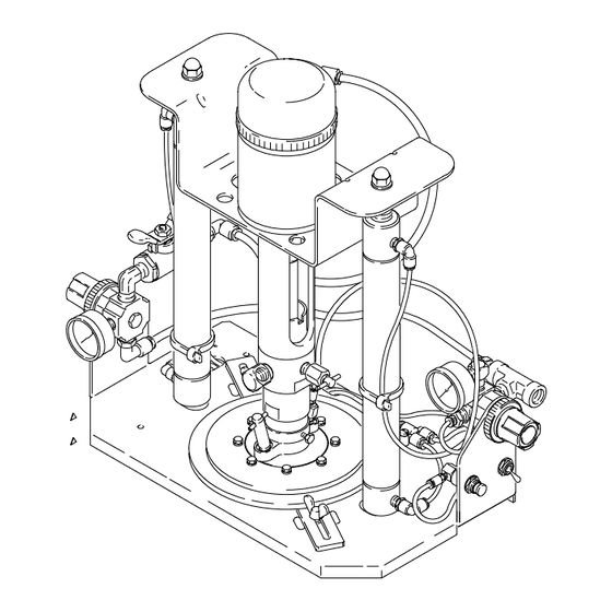
- Page 7 Installation Wiper Plate Assembly Ram Air Regulator Pump Fluid Outlet Fitting Bleed-Type Master Air Valve Air Assist Valve Connector Pump Fluid Intake Housing Air Inlet Air Assist Valve (Pushbutton) Air Line to Wiper Plate Pump Bleeder Valve Capscrews Pump Air Regulator Wiper Plate Connector Order Wiper Plate (P) separately.
- Page 8 Notes 308302...
- Page 9 Installation System Accessories (See Fig. 2) D The pump air regulator (27a) controls pump speed and outlet pressure by adjusting the air pressure to the pump. The regulator is located WARNING upstream from the bleed-type master air valve. Two required safety devices are supplied with your D The ram air regulator (27b) controls ram speed by pump: a bleed-type master air valve (8) and a adjusting the air pressure to the ram, and also...
-
Page 10: Operation
Operation Pressure Relief Procedure WARNING WARNING Keep hands and fingers away from the priming piston and pump intake during operation and PRESSURIZED EQUIPMENT HAZARD whenever the pump is charged with air. During The system pressure must be manually relieved to operation, the priming piston extends beyond the prevent the system from starting or spraying acci- intake housing to pull material into the pump, and... - Page 11 Operation Starting and Adjusting the Ram NOTE: If the wiper plate does not enter the can easily, increase the ram pressure; once it enters the can, 1. Refer to Fig. 3. Be sure all air regulators and immediately reduce the pressure. bleed-type air valves are closed.
- Page 12 Operation Wiper Plate Assembly Fluid Outlet Fitting Pump Ram Director Valve Bleed-Type Master Air Valve Air Tube Air Assist Valve (Pushbutton) Clamp Wing Screws Clamps Wiper Plate Screws Pump Bleeder Valve Wiper Bleed Valve Pump Air Regulator Wiper Plate Ring Ram Air Regulator Order Wiper Plate (P) separately.
- Page 13 Operation Changing Fluid Cans 4. Loosen the clamps (24) and remove the empty can. Set the full can on the ram base and position it under the wiper plate. If the can has a welded 1. Stop the pump. Close the bleed-type master air seam, position it with the seam facing the rear of valve (8), but leave air pressure on to the ram.
-
Page 14: Troubleshooting
Troubleshooting Before servicing this equipment always make sure to WARNING Relieve the Pressure. To reduce the risk of serious injury whenever you are instructed to relieve pressure, always follow the Check all possible problems and solutions before Pressure Relief Procedure on page 10. disassembling the pump. - Page 15 Notes 308302...
- Page 16 Service Disassembly (See Fig. 4) 4. Remove the three remaining screws (138) and washers (141) holding the air motor coupling (105) to the cylinder (102). Pull the cylinder straight up WARNING off the coupling until the air valve housing (103a) clears the air motor piston (104).
- Page 17 Service Torque to 8–10 N.m (72–88 in–lb) Torque to 1.7–2.3 N.m (14–20 in–lb) Apply thread lubricant. Torque to 35–37 N.m (298–314 in–lb) Lips must face down. Apply thread adhesive. Torque to 2–4 N.m (17–33 in–lb) Lubricate. 162{ 163{ 161{ *103c 114{ 103e* *103a...
- Page 18 Service Reassembly (See Fig. 5) 7. Install the large o-ring (103e*) on the outer diame- ter of the air motor coupling (105), and the small o-ring (103c*) in the groove on the inner diameter NOTE: Lubricate all packings and o-rings with a com- of the coupling.
- Page 19 Service Torque to 8–10 N.m (72–88 in–lb) Torque to 1.7–2.3 N.m (14–20 in–lb) Apply thread lubricant. Torque to 35–37 N.m (298–314 in–lb) Lips must face down. Apply thread adhesive. Torque to 2–4 N.m (17–33 in–lb) Lubricate. 162{ 163{ 161{ *103c 114{ 103e* *103a...
- Page 20 Parts Detail A 02095A 34 (REF) 37 59 Detail B 02094B See Detail A above. See Detail B at left. Part of item 1. Part of item 36. Part of item 18. 02095B 308302...
- Page 21 111593 SCREW, ground 1/4–18 npt(m) 110889 NUT, crown; 3/8–24 unf-2b Y Replacement Warning labels, tags, and cards are avail- able at no cost. Part No. 965680 Cartridge Pump (not shown) Part No. Description Qty. 235871 PUMP, Dynamite, includes items 1–99 above.
- Page 22 Parts Order Wiper Plate separately. See page 23. 83 (REF) 02093A Part No. Description Qty. Part No. Description Qty. 186532 TUBE, air; nylon; 6.3 mm (0.250”) OD; 188965 TUBE, air; nylon; 4 mm (0.156”) OD; 4/6 mm (0.180”) ID; 2.7 mm (0.106”) ID; 570 mm (22.44”) long 150 mm (5.91”) long 186533...
- Page 23 Parts NOTE: The Wiper Plate is not supplied with the pump, and must be ordered separately. {309 02096 Model 224908 3 kg (1 Gallon) Size Model 224923 1 kg (1 Quart) Size Includes items 301–312 Includes items 301–312 Part No. Description Qty.
- Page 24 Parts 162† 163† *103c 161† *103e 114† *103a *103b *103d TI0262 308302...
- Page 25 Parts Part No. Description Qty. Part No. Description Qty. 110873 SCREW, cap, hex hd; M5 x 0.8; 186273 CAP, cylinder, aluminum 20 mm (0.79”) long 196082 CYLINDER, air motor 110874 WASHER, flat; no. 5 223895 AIR MOTOR REPAIR KIT 112120 PIN, spring Includes items 103a–103e, 166 111639...
-
Page 26: Technical Data
Technical Data Category Data Maximum fluid output pressure 6.0 MPa, 60 bar (850 psi) Air input pressure range 243–700 kPa, 2.4–7.0 bar (35–100 psi) Maximum fluid viscosity 600,000 cps volume per stroke (dispenses on down- 5.0 cc (0.17 oz.) stroke only) Recommended pump speed for continu- 40 cpm ous operation... - Page 27 Technical Data KEY: Fluid Outlet Pressure – Black Curves NOTE: Recommended pump speed for continuous operation: 40 cpm Air Consumption – Gray Curves Maximum recommended pump speed (to shaded area): 60 cpm cycles/min 1000 0.7 MPa, 7 bar (100 psi) air pressure scfm 0.168...
- Page 28 Dimensions LOWERED: 444.5 mm (17.5 in.) RAISED: 673.1 mm (26.5 in.) 1/4 npt(f) FLUID OUTLET 1/4 npt(f) AIR INLET WIDTH OF BASE ONLY: 355.6 mm (14.0 in.) WIDTH INCLUDING AIR REGULATORS 209.6 mm (8.25 in.) 431.8 mm (17.0 in.) 02091A 308302...
-
Page 29: Manual Change Summary
Manual Change Summary Models 235870 and 235871 use a new air valve and advance to series C. Part No. 965680 Cartridge Pump is added to the manual. 308302... -
Page 30: Graco Standard Warranty
Graco’s written recommendations. This warranty does not cover, and Graco shall not be liable for general wear and tear, or any malfunction, damage or wear caused by faulty installation, misapplication, abrasion, corrosion, inadequate or improper maintenance, negligence, accident, tampering, or sub- stitution of non–Graco component parts.
Need help?
Do you have a question about the 965680 and is the answer not in the manual?
Questions and answers