
Subscribe to Our Youtube Channel
Related Manuals for B.A. International Optima OS600L


Summary of Contents for B.A. International Optima OS600L
- Page 1 Optima OS600L Instructions for Use Implant and Surgical Unit BA160510 / 9795068 / ISE-270M language EN 2-15p / ES 16~30p / FR 31~45p / IT 46~60p / NL 61~75p / DE 76~90p...
- Page 2 Instructions for use Implant and Surgical Unit BA160510 / 9795068 Symbols Contents Catalog number Chapter 1. Introduction Serial number Chapter 2. Safety Information (Precautions and Warning) Manufacturer Chapter 3. Description Authorized representative in the European Community Chapter 4. Installation Manufacturing Date BF type applied part Chapter 5.
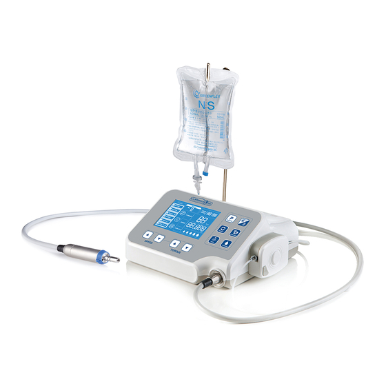
- Page 3 Chapter 1. Overview 1.1 Operating Principle This device is an unit that consists of a main body, BLDC (brushless DC) motor, and foot pedal switch for driving and operating a handpiece for dental implant procedures, to be used in dentistry in the field of implant surgery. The main body of this device is powered by an external power supply that converts alternating current to direct current, which turns the BLDC motor;...
- Page 4 2.3 Caution 1) Never attempt to disassemble or modify the device. Once the device is disassembled,you will no longer be entitled to after sales service from the manufacturer. 2) Never add oil to the inside of the BLDC motor. This can cause the bearings to malfunction and get hot. 3) Do not use thinner, benzene or any other solvents to clean.
- Page 5 3.1.1 Main Controller (BA160510) 1) Front 2) Rear Power cable terminal Connection for irrgation hanger Display Rotation button Program button Memory button Gear ratio button Coolant button Water injection Groove on pipe fixture irrigation hanger Motor connection Speed Up/Down button Torque Up/Down button Optic LED button Fuse box Power switch...
- Page 6 3.2 Product Performance 1) Main controller (BA160510) Power Supply voltage 220V Frequency 60HZ Power Consumption 150VA Max. Coolant flow rate 130 ml/min Fuse 2 × 250 × T2.0AH Dimension 300×230×135 ㎜ [Width×Length×Height] 2) Motor (BA160530) Max. Speed 40,000 rpm Max. Torque 7 Ncm Max.
- Page 7 Chapter 4. Installation 4.1 Installation of hanger and Foot switch hanger 4.1.1 Installation of hanger 4.1.2 Installation of Foot switch hanger ① Insert foot switch hanger into hanger hole. ① Insert irrigation hanger into hanger hole. ② Fix by connecting hanger bolt. ②...
- Page 8 4.4 Installation of irrigation tube External spray nozzle Irrigation tube Irrigation tube ③ Open Irrigation cover by pressing Push button. ① Attach the irrigation tube to the straight Push button or contra-angle handpiece. Irrigation tube Tube clip ④ Put Irrigation tube in the groove. Connect irrigation cover ⑤...
- Page 9 Chapter 5. Operation 5.1 General use 1) Turn on the Power switch of implant engine controller ① Connect the engine to the power cable. ② Turn the engine on at the power switch. 2) Programs are selected in turn by pressing Foot switch or P button of implant engine controller. 3) Check the displayed torque, rotation speed, irrigation flow rate, gear ratio and direction of rotation.
- Page 10 5.2 Program Mode 5.2.1 Selecting a program A user selects a program necessary for surgery with this button. Program cycles through numbers 1 to 6 when pressing the program button each time. It changes in order of Drilling→Tapping→Remove Tap→Implant→Remove→Rock screw. Program A white border highlights the selected program.
- Page 11 5.3 Memory function 5.3.1 Memory button Press the memory button to access memory address where detailed figures (Gear ratio, Torque, Speed, For/Rev, Coolant) of each function in program are saved. Memory address cycles through numbers 1 to 9 upon pressing Memory button each time. Memory 1 Memory 9 Memory...
- Page 12 5.4 Setting direction of motor rotation The initial setting is Forward direction and Reverse is selected upon pressing the button The letters "REV" and arrow are turned on upon selecting Reverse, and a beep will sound. ① The letters "FOR" and arrow are turned on upon selecting Forward. FOR.
- Page 13 5.8 Change in torque value Torque section on the display flashes upon pressing torque button. Torque is controlled using the button for adjusting set value. Torque setting mode is exited by pressing Torque button again or another button for another function or when the motor is operated. Gear ratio Torque(Ncm) Gear ratio...
- Page 14 Chapter 6. Maintenance 6.1 Manual cleaning 1) Separate the motor and Foot Switch connected in the Control Unit. 2) Prepare a cloth (preferably cotton) or soft brush moistened with isopropyl alcohol. 3) Clean foreign substance on the entire surface and in the gaps with cloth or brush soaked in isopropyl alcohol for at least 3 minutes. 4) Repeat the cleaning process if foreign substance is found.
- Page 15 Chapter 7. Troubleshooting 7.1 Description of Error Message 7.1.1 Error display screen Upon occurrence of error, a warning sound is made and then the number subject to the error flickers on error display part of the screen. Error code Status Cause of error Remedy Defective motor hall sensor,...
- Page 16 (BA160545) (BA160546) (BA160547) (BA160548) 8.2 Information on After-Sale Service ▶ Distributor: B.A. International Ltd. ▶ Address: Unit 9, Kingsthorpe Business Centre, Studland Road, Northampton, NN2 6NE, UK. ▶ Contact: +44 (0)1604 777700 info@bainternational.com www.bainternational.com ▶ Made in : Republic of Korea 8.3 Warranty...
- Page 17 Annex A 10.1 Electromagnetic Compatibility The product is suitable for use in an specific electromagnetic environment. The customer and/or the user of the product should assure that it is used in an electromagnetic environment as described below. Emission Test Compliance Electromagnetic Environment Guidance The product use RF energy only for its internal function.
- Page 18 Emission Test IEC 60601- Level Compliance Level Electromagnetic Environment Guidance Portable and mobile RF communications equipment should be used no closer to any part of the product, including cables, than the recommended separation distance calculated 3 Vrms Conducted RF from the equiation applicable to the frequency of the transmitter. 3 Vrms 150 kHz IEC 61000-4-6...
- Page 20 The EU directive 93/42/EEC was applied in the design and production of this medical device Distributor: B.A. International Ltd. Address: Unit 9, Kingsthorpe Business Centre, Studland Road, Northampton, NN2 6NE, UK. Contact: +44 (0)1604 777700 info@bainternational.com www.bainternational.com MicroNX co., branch office Address: Karl-Marx-Str.
Need help?
Do you have a question about the Optima OS600L and is the answer not in the manual?
Questions and answers