
Subscribe to Our Youtube Channel
Related Manuals for Campbell MS-80SH


Summary of Contents for Campbell MS-80SH
- Page 1 PRODUCT MANUAL MS-80SH Class A Digital Pyranometer with SDI-12 and Modbus Output 06/2024 Copyright © 2024 Campbell Scientific, Inc.
- Page 2 U.S. standard external power supply details where some information (for example the AC transformer input voltage) will not be applicable for British/European use. Please note, however, that when a power supply adapter is ordered from Campbell Scientific it will be suitable for use in your country.
-
Page 3: Table Of Contents
5.4 Mounting procedure 6. Operation 6.1 SDI-12 commands 6.2 SDI-12 extended commands 6.3 RS-485 default configuration 6.4 MS-80SH register map 7. Maintenance and troubleshooting Appendix A. SDI-12 sensor support A.1 SDI-12 command basics A.1.1 Acknowledge active command (a!) A.1.2 Send identification command (al!) A.1.3 Address query command (?!) - Page 4 A.2 SDI-12 transparent mode A.2.1 Changing an SDI-12 address Table of Contents -...
-
Page 5: Introduction
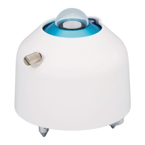
Modbus RTU 485 or SDI-12 output; and a five-year warranty and recalibration interval. The MS-80SH has a dome heater, internal temperature and humidity sensors, and a tilt sensor. These internal sensors monitor the stability of the irradiance sensors and ensures proper installation and maintenance. -
Page 6: Specifications
8 to 30 VDC Irradiance range: 0 to 4000 W/m Dimensions Diameter (including sun screen): 9.6 cm (3.8 in) Body height: 7.3 cm (2.9 in) Dome height: 1.2 cm (0.5 in) MS-80SH Class A Pyranometer with SDI-12 or RS-485 Modbus Communication... -
Page 7: Installation
Not used U and C terminals are automatically configured by the measurement instruction. If multiple SDI-12 sensors are connected to a data logger, Campbell Scientific recommends using separate terminals when possible. However, multiple SDI-12 sensors can connect to the same... -
Page 8: Programming
For the CR6 and CR1000X data loggers, triggering conflicts may occur when a companion terminal is used for a triggering instruction such as TimerInput(), PulseCount(), or WaitDigTrig(). For example, if the MS-80SH is connected to C3 on a CR1000X, then C4 cannot be used in the TimerInput(), PulseCount(), or WaitDigTrig() instructions. -
Page 9: Modbus Crbasic Programming
The RS-485 output can be directly read by a MeteoPV, CR6-series, CR1000X, or Modbus RTU RS-485 network. Other Campbell Scientific data loggers can use an MD485 multidrop interface to read the RS-485 output (refer to the MD485 manual). Refer to www.campbellsci.com/videos/meteopv... -
Page 10: Mounting Procedure
For pyranometers mounted horizontally, ensure the mounting bracket is horizontal in two dimensions. For pyranometers mounted at an angle, set the mounting bracket angle to the desired angle prior to tightening the mounting hardware. MS-80SH Class A Pyranometer with SDI-12 or RS-485 Modbus Communication... -
Page 11: Operation
A C! command follows the same pattern as an M! command with the exception that it does not require the data logger to pause its operation until the values are ready. Rather, the data logger MS-80SH Class A Pyranometer with SDI-12 or RS-485 Modbus Communication... - Page 12 As measurement data is transferred between the MS-80SH and data logger digitally, no offset errors are incurred with increasing cable length as seen with analog sensors. However, an increase in cable length does reach a point when digital communications break down, resulting in either no response or excessive SDI-12 retries and incorrect data due to noise problems.
-
Page 13: Sdi-12 Extended Commands
Enter the following SDI-12 extended commands using the transparent mode while the computer is communicating with the data logger through a terminal emulator program. It is accessed through Campbell Scientific Device Configuration Utility software or other terminal emulator programs. Data logger keyboards and displays cannot be used. Refer to... -
Page 14: Rs-485 Default Configuration
Y-axis tilt angle Intensity of solar radiation before Float W/m² correction Float Sensor output voltage Float Sensor voltage output with three decimals Float °C Internal temperature Float % RH Internal humidity MS-80SH Class A Pyranometer with SDI-12 or RS-485 Modbus Communication... -
Page 15: Maintenance And Troubleshooting
7. Maintenance and troubleshooting The MS-80SH has no service items that require scheduled replacement. There is no accessible desiccant cartridge to maintain. Use pure alcohol or distilled water and a lint-free cloth to clean the dome, removing smears and deposits. Local conditions and application dictate a cleaning interval. -
Page 16: Appendix A. Sdi-12 Sensor Support
Serial Data Interface at 1200 baud (SDI-12 ) is a protocol developed to simplify sensor and data logger compatibility. Only three wires are necessary—serial data, ground, and 12 V. With unique addresses, multiple SDI-12 sensors can connect to a single SDI-12 terminal on a Campbell Scientific data logger. -
Page 17: Acknowledge Active Command (A!)
Serial number or other sensor specific information may also be included. Command: aI! Response: allccccccccmmmmmmvvv<CR><LF> Where a = sensor address ll = SDI-12 version number (indicates compatibility) MS-80SH Class A Pyranometer with SDI-12 or RS-485 Modbus Communication... -
Page 18: Address Query Command (?!)
To avoid this, ensure that the scan interval is greater than the longest measurement time (ttt). MS-80SH Class A Pyranometer with SDI-12 or RS-485 Modbus Communication... -
Page 19: Start Concurrent Measurement Commands (Ac!)
The data logger makes a request to sensor X to start a concurrent measurement. Sensor X immediately indicates that it will have 5 X03005<CR><LF> (05) values ready for collection within the next 30 (030) seconds. MS-80SH Class A Pyranometer with SDI-12 or RS-485 Modbus Communication... -
Page 20: Start Concurrent Measurement Commands (Ac!)
This is most commonly implemented when long cable lengths or electronic noise may impact measurement transmission to the data logger. When these commands are used, the data returned in response to D!or R! commands must have a cyclic redundancy check (CRC) code MS-80SH Class A Pyranometer with SDI-12 or RS-485 Modbus Communication... -
Page 21: Continuous Measurement Command (Ar0
<values> = values returned with a polarity sign (+ or –) <CR><LF> = terminates the response <CRC> = 16-bit CRC code appended if data was requested with aMC! or aCC!. MS-80SH Class A Pyranometer with SDI-12 or RS-485 Modbus Communication... -
Page 22: Extended Commands
Transparent mode is entered while the computer is communicating with the data logger through a terminal emulator program. It is accessed through Campbell Scientific data logger support software or other terminal emulator programs. Data logger keyboards and displays cannot be used. - Page 23 CR1000X directly connected to the computer USB port. 4. Select the correct Communication Port and click Connect. 5. Click the Terminal tab. 6. Select All Caps Mode. MS-80SH Class A Pyranometer with SDI-12 or RS-485 Modbus Communication...
- Page 24 12. To exit SDI-12 transparent mode, click Close Terminal. NOTE: The transparent mode for the Granite-series, CR6, CR3000, CR800-series, CR300-series data loggers is similar to that shown for the CR1000X. MS-80SH Class A Pyranometer with SDI-12 or RS-485 Modbus Communication...
- Page 25 2. The defect cannot be the result of misuse. 3. The defect must have occurred within a specified period of time; and 4. The determination must be made by a qualified technician at a Campbell Scientific Service Center/ repair facility.
- Page 26 Campbell Scientific’s Terms, the provisions of Campbell Scientific’s Terms shall prevail. Furthermore, Campbell Scientific’s Terms are hereby incorporated by reference into this Warranty. To view Terms and conditions that apply to Campbell Scientific, Logan, UT, USA, see Terms and Conditions ...
- Page 27 Please state the faults as clearly as possible. Quotations for repairs can be given on request. It is the policy of Campbell Scientific to protect the health of its employees and provide a safe working environment. In support of this policy, when equipment is returned to Campbell Scientific, Logan, UT, USA, it is mandatory that a “Declaration of Hazardous Material and...
- Page 28 Comply with all electrical codes. Electrical equipment and related grounding devices should be installed by a licensed and qualified electrician. Only use power sources approved for use in the country of installation to power Campbell Scientific devices. Elevated Work and Weather Exercise extreme caution when performing elevated work.
- Page 29 Periodically (at least yearly) check electrical ground connections. WHILE EVERY ATTEMPT IS MADE TO EMBODY THE HIGHEST DEGREE OF SAFETY IN ALL CAMPBELL SCIENTIFIC PRODUCTS, THE CUSTOMER ASSUMES ALL RISK FROM ANY INJURY RESULTING FROM IMPROPER INSTALLATION, USE, OR MAINTENANCE OF TRIPODS,...
- Page 30 Campbell Scientific Regional Offices Australia France Spain Location: Garbutt, QLD Australia Location: Montrouge, France Location: Barcelona, Spain Phone: 61.7.4401.7700 Phone: 0033.0.1.56.45.15.20 Phone: 34.93.2323938 Email: info@campbellsci.com.au Email: info@campbellsci.fr Email: info@campbellsci.es Website: www.campbellsci.com.au Website: www.campbellsci.fr Website: www.campbellsci.es Brazil Germany Thailand Location: São Paulo, SP Brazil...
Need help?
Do you have a question about the MS-80SH and is the answer not in the manual?
Questions and answers