
Subscribe to Our Youtube Channel
Related Manuals for Campbell TDR100


Summary of Contents for Campbell TDR100
- Page 1 TDR100 Revision: 2/10 C o p y r i g h t © 2 0 0 0 - 2 0 1 0 C a m p b e l l S c i e n t i f i c ,...
- Page 2 Warranty and Assistance The TDR100 is warranted by CAMPBELL SCIENTIFIC, INC. to be free from defects in materials and workmanship under normal use and service for twelve (12) months from date of shipment unless specified otherwise. Batteries have no warranty. CAMPBELL SCIENTIFIC, INC.'s obligation under this warranty is limited to repairing or replacing (at CAMPBELL SCIENTIFIC, INC.'s option) defective products.
-
Page 3: Table Of Contents
2.2.1 TDR100 ..................2 2.2.2 SDMX50..................2 2.3 TDR100 Performance Specifications ............2 2.4. Electromagnetic Compatibility ..............3 3. Getting Started with TDR100 using PCTDR ....3 3.1 Discussion of Distances and Propagation Velocity (Vp) when using TDR100....................4 3.2 PCTDR Help.....................6 4. PCTDR Software ............6 4.1 General......................7... - Page 4 5.8.1 Determining Probe Constant, Kp, using PCTDR......18 6. Datalogger Instructions for TDR Measurements ..18 6.1 CR800, CR850, CR1000, or CR3000 Datalogger Instruction “TDR100”18 6.2 CR10X and CR23X Datalogger Instruction 119 ........20 6.3 Discussion of TDR Instruction Parameters (Instruction 119)....21 6.3.1 Parameter 1: SDM Address............
- Page 5 10, 18, 26, 30 and 37%. Solution electrical conductivity is 10.2 dS m ..............30 9-1. Typical TDR100 waveform showing key features with numbers 1, 2 and 3....................31 9-2. PCTDR terminal emulator screen showing TDR100 algorithm parameter variables ................32 9-3.
- Page 6 TDR100 Table of Contents...
-
Page 7: Introduction
The TDR100 and SDMX50 multiplexers can be configured for automatic control using the dataloggers. A single TDR probe can be connected directly to the TDR100 or multiple probes connected via coaxial multiplexer units (SDMX50). Warning The TDR100 is sensitive to electrostatic discharge damage. -
Page 8: System Specifications
• When the TDR100 is controlled by a datalogger, a 35 second timer puts the device in sleep mode requiring about 20 milliamps. After 35 seconds in sleep mode, a timer puts the TDR100 in standby mode requiring about 2 milliamps. -
Page 9: Electromagnetic Compatibility
3. Getting Started with TDR100 using PCTDR This section lists steps for a simple connection between a computer and the TDR100 to monitor a single TDR probe using PCTDR software. A single probe is connected directly to the TDR100, and no multiplexers are used. -
Page 10: Tdr100
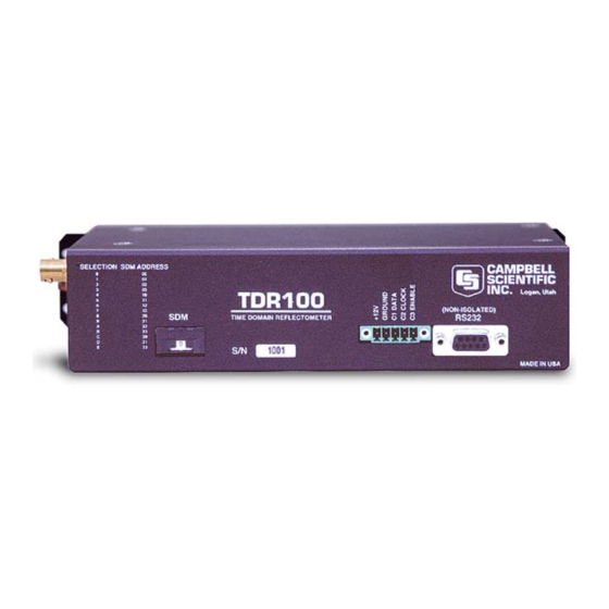
Settings/Communications. The baud rate is factory set to 57600. 3. Connect 12 volt power to TDR100 12 volt power to the TDR100 is connected using terminals +12V and GROUND on the panel 5-terminal connector. An external power supply or the 12V terminals of a datalogger can be used for power. The C1, C2 and C3 terminals are for SDM (synchronous device for measurement communication protocol) communications. -
Page 11: Waveform Of A Cs610 In Water
TDR100 FIGURE 3-1. Waveform of a CS610 in water. Changing the Waveform Start value to 5.7 m and the Waveform Length to 5 m gives the waveform displayed in Figure 3-2. -
Page 12: Pctdr Help
4. PCTDR Software A display for viewing waveforms is generally needed only for system setup and troubleshooting, and the TDR100 does not have a built-in display. Windows software PCTDR is used with a personal computer to configure the TDR100 and multiplexers and display waveforms. -
Page 13: General
4.1 General PCTDR requires a connection from a COM port of the computer to the RS-232 port of the TDR100. Choice of COM port and baud rate is made in PCTDR menu Settings/Communications. The baud rate is set during TDR100 production to 57600. -
Page 14: Menu Selections
It is only necessary to know the V value if the TDR100 is used as a cable tester for finding cable lengths or faults. See Section 3.1 for a discussion of propagation velocity. -
Page 15: Waveform
Average - sets the number of measurements averaged at a given distance from the TDR100. A value of 4 is recommended. Higher values can be used when noise is present. Averaging is useful when noise from power sources or when noise of random nature is superimposed on the reflection waveform. -
Page 16: Pctdr Waveform For Cs610 In Water
TDR100 FIGURE 4-1. PCTDR waveform for CS610 in water. The algorithm will use the length of the waveform set by the Waveform Length. After finding the probe beginning, the algorithm searches over the remaining waveform for the end of the probe. The length must be large enough to display a short distance past the end of the probe under the wettest expected conditions. -
Page 17: System Components: Datalogger Control
5.2 Datalogger Campbell Scientific CR800, CR850, CR1000, and CR3000 dataloggers use Instruction “TDR100” to control the TDR100 measurement sequence and store the resulting data. PC400 or LoggerNet (version 3.0 or higher) are used to create and send the CRBasic Program to the datalogger. -
Page 18: Tdr100
TDR100 5.3 TDR100 The TDR100 contains the pulse generator for the signal applied to a TDR probe. The TDR100 also digitizes the reflection and applies numerical algorithms for measuring volumetric water content or electrical conductivity. The TDR100 communicates with the datalogger using SDM protocol or with a computer using PCTDR and serial communications. -
Page 19: Power Supply
FIGURE 5-3. Terminal Strip Adapters for Connections to Battery Campbell Scientific recommends using datalogger switched 12 volts to power the TDR100. This will provide power savings and will automatically reset the TDR100 and provide automatic recovery from system malfunctions. This practice can reduce loss of measurement data when a problem exists. -
Page 20: Sdm Communication
Table 5-1 lists Edlog addresses (base 4) and jumper positions associated with them. It is recommended to use a TDR100 address of 0, level 1 SDMX50 address of 01, level 2 SDMX50 address of 02, and level 3 SDMX50 address of 03. -
Page 21: Location Of Address Jumpers On Sdmx50
TDR100 FIGURE 5-4. Location of Address Jumpers on SDMX50 TABLE 5-1. SDM Addressing for Early SN SDMX50s and Edlog Dataloggers Level 1 Level 2 SDMX50 Level 3 SDMX50 TDR100 SDMX50 Mux Muxs Muxs Base 10 Instruction 119 Thumbwheel (TDR100+1) (TDR100+2) -
Page 22: Sdm Cable And Cable Length Considerations
A 5-conductor cable with shield and drain is used for interconnection of SDM devices. The 5 conductors are used for 12 volt power, ground and the 3 SDM lines. A cable assembly (pn13776) is provided with the TDR100 and the ENCTDR100. This assembly is for SDM connection between the TDR100 and a datalogger and between the TDR100 and a SDMX50 multiplexer. -
Page 23: Soil Probes
PS12 power supply, CR10X PS12 BATTERY EXTERNAL BATTERY - DO NOT USE WITH INTERNAL RECHARGEABLE BATTERY CHARGE VOLTAGE PRESENT datalogger, TDR100, and INPUT FROM CHARGER OR SOLAR PANEL 16-26 VDC OR AC RMS: POSITIVE TO EITHER TERMINAL, NEGATIVE TO OTHER SDMX50SP coaxial... -
Page 24: Determining Probe Constant, Kp, Using Pctdr
6. Datalogger Instructions for TDR Measurements 6.1 CR800, CR850, CR1000, or CR3000 Datalogger Instruction “TDR100” The TDR100 instruction is used to measure one or more time domain reflectivity (TDR) probes attached to a TDR100 device. Syntax TDR100 ( Dest, SDMAddress, Option, Mux/ProbeSelect, WaveAvg, Vp,... - Page 25 TDR100 SDMAddress: The SDMAddress parameter defines the address of the TDR100 with which to communicate. Valid SDM addresses are 0 through 14. Address 15 is reserved for the SDMTrigger instruction. If the Reps parameter is greater than 1, the datalogger will increment the SDM address for each subsequent TDR100 that it communicates with.
-
Page 26: Cr10X And Cr23X Datalogger Instruction 119
This value is supplied by Campbell Scientific for the probes we manufacture. The value of this parameter only has an affect when Option 0, La/L, is used for the measurement. -
Page 27: Discussion Of Tdr Instruction Parameters (Instruction 119)
The SDM address of the TDR100 is set by selecting hexadecimal values with the thumbwheel switch on the TDR100 front panel. Instruction 119 requires a 2 digit integer that is the base 4 value of the TDR100 address. See Table 5-1 6.3.2 Parameter 2: Output Option 6.3.2.1 Enter 0: Measure La/L... -
Page 28: Enter 1: Collect Waveform
TDR100 6.3.2.2 Enter 1: Collect Waveform The digitized reflection waveform can be collected from the TDR100 by the datalogger in ASCII format. Datalogger input storage must be manually allocated for the waveform data points using “block allocation” in Edlog datalogger software. The waveform is collected as an array. The first 9 cells of the array is a header and contain values entered in Instruction 119. -
Page 29: Parameter 4: Waveform Averaging
6.3.4 Parameter 4: Waveform Averaging Sets the number of measurements averaged at a given distance from the TDR100. A value of 4 is recommended. Higher values can be used when noise is present. Averaging is useful when noise from power sources or when noise of random nature is superimposed on the reflection waveform. -
Page 30: Parameter 8: Window Length (Meters)
Most TDR probes have a block of epoxy or other material which holds the rods rigidly spaced and houses an impedance matching transformer (balun) if used. The algorithm in the TDR100 uses changes in the reflection coefficient to identify end points of the probe. The transition from the coaxial cable to the... -
Page 31: Parameter 12: Multiplier
TDR100 TABLE 6-1. Reflection waveform array header elements. Description of Array Header Elements averaging propagation velocity number of data points cable length window length probe rod length probe offset multiplier offset 6.3.12 Parameter 12: Multiplier Multiplication factor applied to the value stored in the input location specified in parameter 11. -
Page 32: Tdr Principles
Laboratory calibrations were performed to determine a K value for the CS600, CS605 and CS610 probes with the following results. TABLE 6-2. Probe Constant Values for Campbell Scientific Probes Probe model probe constant (K CS600 3.16... - Page 33 − 01138 01758 The TDR100 generates a very fast rise time pulse that is sent to the connecting cable and probe. Reflections over a specified length of transmission line are sampled and digitized. Discontinuities in cable impedance will cause changes in the amplitude of the reflected signal.
-
Page 34: Cable Length And Soil Electrical Conductivity Effect On Water Content Determination
TDR probe. The pulse generated by the TDR100 and its reflections are subject to distortion during travel between the TDR100 and the TDR probe. The cable connecting the probe to the reflectometer has a characteristic impedance resulting in both resistive and reactive losses. -
Page 35: Soil Electrical Conductivity Effect On Water Content Measurement
RG8. Careful probe design ensures correct probe impedance giving robust reflections. All TDR probes offered by Campbell Scientific are designed to optimize accuracy when longer cable lengths are used. -
Page 36: Algorithm Description And Parameter Adjustment
TDR measurements are taken. 9. Algorithm Description and Parameter Adjustment 9.1 Introduction This section presents a general description of the algorithms in the TDR100 for electrical conductivity and water content measurement. 9.2 Algorithm for Calculation of TDR Probe Rod Apparent Length 9.2.1 Algorithm Description... -
Page 37: Waveform Evaluation
FIGURE 9-1. Typical TDR100 waveform showing key features with numbers 1, 2 and 3. The algorithm to calculate apparent length uses both the waveform values and the first derivative of the waveform to identify the beginning and end of the probe. -
Page 38: Algorithm Parameter Adjustment For Special Conditions
The standard settings for the apparent length algorithm work well for nearly all applications. For special cases of very long cables or some probes that are not manufactured by Campbell Scientific an algorithm parameter change can improve results. The parameter discussed here affects how the algorithm finds the beginning of the TDR probe. -
Page 39: Algorithm For Calculation Of Bulk Electrical Conductivity
TDR100 to calculate bulk electrical conductivity. The electrical conductivity calculation uses waveform values for the region immediately before the TDR probe and values from about 200 meters from the TDR100. The value at the location before the probe is used to calculate the applied signal and the 200 meter values are used for the reflected signal. -
Page 40: Waveform And Derivative Values Near Tdr Probe And Locations Of
TDR100 To view the current parameter values type GECP at the > prompt. The values of the 4 parameters are returned. The default values for the threshold equation are: a = 0 b = 1 c = 2 Therefore the default threshold is the mean plus twice the standard deviation of the values in the 10-point window before the probe. -
Page 41: Programming Examples
TDR100 10. Programming Examples 10.1 CR1000 Program Example Example 1, Measure and Record; Analog Measurements, Volumetric Water Content, and Capture TDR Probe Waveforms Equipment Wiring CR1000 TDR100 SDMX50 SW12 +12 V 12 V Sensor Wiring TDR100 SDMX50 Probe* Coax Common... - Page 42 'Define Data Tables ---------------------------------------------- DataTable (Dat15min,1,-1) '15-minute Data Table (i.e. Analog Measurements) DataInterval (0,15,Min,10) Minimum (1,batt_volt,IEEE4,0,False) Average (1,Panel_temp,IEEE4,0) EndTable DataTable (Data_TDR,1,-1) '2-Hour Data Table (i.e. TDR100 VWC Measurements) DataInterval (0,120,Min,10) Minimum (1,batt_volt,IEEE4,0,False) Average (1,Panel_temp,IEEE4,0) Sample (8,LaL(),IEEE4) sample (8,LedieuVWC(),FP2) sample (8,ToppVWC(),FP2) EndTable DataTable (TDR_Wave,1,240) 'Data Table (i.e.
- Page 43 '************************************* SW12 (1) 'Turn on 12V Power to TDR100 & SDMX50 'Note: Wire TDR100 & SDMX50 12V power leads to CR1000 SW12 Terminal Delay (1,2,Sec) 'pause 2 sec to allow power supply voltage to settle 'Measure La/L on SDMX50 channel #1 thru channel#8 & convert to VWC using Topp Eq.
-
Page 44: Cr10X/Cr23X Program Examples
10.2 CR10X/CR23X Program Examples Example 1, Measure and Record; Analog Measurements and Volumetric Water Content A CS605 or CS610 probe is connected directly to the TDR100. A cable length of 6.25 meters was determined using PCTDR. The L /L value is converted to volumetric water content using the Ledieu , etal linear calibration function. - Page 45 ;Measure the internal temperature of the datalogger: 2: Internal Temperature (P17) 1: 2 Loc [ DL_Temp ] ;Set port 5 high to switch ON "Switched 12V" power from the datalogger to power the TDR100. 3: Do (P86) 1: 45 Set Port 5 High ;Measure the CS610 probe connected directly to the TDR100 and convert to water content:...
- Page 46 TDR100 ;Output a time stamp; year, day, and hour/minute: 7: Real Time (P77) 1: 1220 Year,Day,Hour/Minute (midnight = 2400) ;Output the minimum Battery Voltage: 8: Minimum (P74) 1: 1 Reps 2: 0 Value Only 3: 1 Loc [ Bat_Volt ] ;Output the average Datalogger temperature and water content...
- Page 47 ;Measure the internal temperature of the datalogger: 3: Internal Temperature (P17) 1: 2 Loc [ DL_Temp ] ;Set port 5 high to switch ON "Switched 12V" power from the datalogger to power the TDR100. 4: Do (P86) 1: 45 Set Port 5 High ;Measure the CS610 probe connected to Channel 3 of the level 1 SDMX50 and return La/L.
- Page 48 5: .292 6: -0.055 7: 0.0043 8: 0.0 9: 0.0 ;Measure Electrical Conductivity on the same CS610 TDR probe connected to Channel 3. 9: TDR100 Measurement (P119) 1: 0 SDM Address 2: 3 Electrical Conductivity 3: 3001 MMMP Mux & Probe Selection...
- Page 49 TDR100 ;Turn off the switched 12V to power off the TDR100: 11: Do (P86) 1: 55 Set Port 5 Low ;Set the Output Flag to output data each time measurements are made: 12: Do (P86) 1: 10 Set Output Flag High (Flag 0) ;Output a time stamp;...
- Page 50 ;Program Name: T100EX#3 *Table 1 Program 01: 120 Execution Interval (seconds) ;Set port 5 high to switch ON "Switched 12V" power from the datalogger to power the TDR100. 1: Do (P86) 1: 45 Set Port 5 High ;Measure the 8 CS610 probes connected to the level 1 SDMX50, return La/L: ;When creating the program with Edlog, the user must manually allocate the 8 input...
- Page 51 TDR100 4: Beginning of Loop (P87) 1: 0 Delay 2: 8 Loop Count ;Square La/L to convert to dielectric constant: ;Note: The user must manually allocate 8 input locations "WC_1" through WC_8". 5: Z=X*Y (P36) 1: 1 -- X Loc [ LaL_1...
- Page 52 Example 4, Measure and Record; Analog Measurements and Volumetric Water Content In this example analog measurements are made every 5 minutes and TDR100 measurements are made every 60 minutes. Twenty-nine CS605 or CS610 probes are connected to 4 SDMX50 multiplexers (Figure 10-1). The cable length values were determined using PCTDR.
- Page 53 2: 60 Interval (same units as above) 3: 30 Then Do ;Set port 5 high to switch ON "Switched 12V" power from the datalogger to power the TDR100. 4: Do (P86) 1: 45 Set Port 5 High ;Measure the 6 CS610 probes connected to the Level 1 SDMX50 ;(Channels 3 to 8) and convert to water content:...
- Page 54 TDR100 6: TDR100 Measurement (P119) 1: 00 SDM Address 2: 0 La/L 3: 1108 MMMP Mux & Probe Selection 4: 4 Waveform Averaging 5: 1 6: 250 Points 7: 9.5 Cable Length (meters) 8: 5 Window Length (meters) 9: .3 Probe Length (meters) 10: .085...
- Page 55 TDR100 ;Turn off the switched 12V to power off the TDR100: 9: Do (P86) 1: 55 Set Port 5 Low ;Now, after making the measurements, set the output flag. ;Remember this is only done once an hour 10: Do (P86)
-
Page 56: Twenty-Nine Cs605 Or Cs610 Probes Connected To 4Ea Sdmx50
TDR100 FIGURE 10-1. Twenty-nine CS605 or CS610 probes connected to 4ea SDMX50 multiplexers. Example 5, Trouble Shooting Program for SDMX50 Multiplexer, Datalogger Control Ports, and Analog Measurements The following program can be used to test the operation of the SDMX50 Multiplexer and the datalogger control ports. - Page 57 TDR100 ;NOTE: While Flag 1 is high Instruction 109 will take control of the ;SDM ports 1-3. It may not be possible to follow the ports ;going High and low with a voltmeter while this is happening. 2: If Flag/Port (P91)
- Page 58 TDR100...
- Page 60 Campbell Scientific Companies Campbell Scientific, Inc. (CSI) 815 West 1800 North Logan, Utah 84321 UNITED STATES www.campbellsci.com • info@campbellsci.com Campbell Scientific Africa Pty. Ltd. (CSAf) PO Box 2450 Somerset West 7129 SOUTH AFRICA www.csafrica.co.za • cleroux@csafrica.co.za Campbell Scientific Australia Pty. Ltd. (CSA)
Need help?
Do you have a question about the TDR100 and is the answer not in the manual?
Questions and answers