Sign In
Upload
Manuals
Brands
Campbell Manuals
Measuring Instruments
SkyVUE Pro
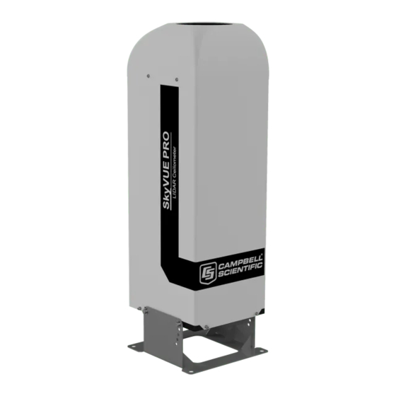
Campbell SkyVUE Pro LIDAR Ceilometer Manuals
Manuals and User Guides for Campbell SkyVUE Pro LIDAR Ceilometer. We have
3
Campbell SkyVUE Pro LIDAR Ceilometer manuals available for free PDF download: Product Manual, Manual
Campbell SkyVUE Pro Product Manual (137 pages)
LIDAR Ceilometer
Brand:
Campbell
| Category:
Accessories
| Size: 2 MB
Table of Contents
Table of Contents
2
General Information
6
Packing List
6
General Safety
6
Sensor Unit Safety
7
Laser Safety
7
Electrical Safety
8
Product Overview
9
Introduction
10
Cloud Height Detection
11
Sky Condition
11
Backscatter Profile Reporting
12
Mixing Layer Height
12
Optical Measurement
13
Optical Arrangement
13
Internal Monitoring
13
FIGURE 2-1. Principle of Operation
13
Specifications
14
Measurement Specifications
14
Mechanical Specifications
14
Electrical Specifications
15
FIGURE 2-2. Skyvue PRO Dimensions
15
FIGURE 2-3. PSU Types
16
Optical Specifications
17
Environmental Specifications
17
Communications Specifications
17
Initial Preparation and Checks
18
Installation
19
Location and Orientation
19
Grounding
20
Mounting the Skyvue PRO
20
Tilt Angle
21
FIGURE 4-1. Mounting Base Footprint
21
Connectors and Wiring
22
FIGURE 4-2. Setting the Tilt Angle
22
Base Connectors
23
FIGURE 4-3. Connector Layout
23
Table 4-1: Function of the Connector Pins for the Mains Connector
23
Wiring Using Supplied Campbell Scientific Cables
24
Table 4-2: Function of the Connector Pins for the Blower/Heater Connector
24
Table 4-3: Function of the Connector Pins for the Communications Connector
24
Power Connections
25
Communications Connections
26
FIGURE 4-4. Cable Connections
26
USB Connection
27
Connection
27
Connecting the Back-Up Battery
27
FIGURE 4-5. USB Port
27
Removing the Cover
28
Removing the Enclosure Lid
28
Bird Spike Kit
29
Storage Information
31
Operation
32
Terminal Mode
32
Entering/Exiting the Skyvue PRO Terminal Mode
32
Terminal Mode Commands General
33
Terminal Mode Command Examples
34
Table 5-1: Summary of the Terminal Mode Commands Available
35
Application Command Message Types
49
Table 5-2: Summary of Applications and Applied Settings for Skyvue PRO
50
MCFG Command Message Types
51
Table 5-3: Summary of Message ID and Descriptions
51
Measurement and Message Intervals
52
Status Command
54
Message Polling
63
Loading a New Operating System (OS)
64
Stratocumulus Backscatter Calibration
67
Codes on Terminal Commands
69
Service Command
70
Locked Features
71
Restoring Factory Defaults
71
LED Indicator
72
Messages
73
Data Messages General
73
Checksums Used in Skyvue PRO Messages
73
CS Messages
74
MESSAGE 001 (no Profile, no Sky Condition)
74
Table 6-1: most Significant Alarm Word for CS Messages
75
Table 6-2: Middle Alarm Word for CS Messages
76
Table 6-3: Least Significant Alarm Word for CS Messages
77
MESSAGE 002 (Profile, no Sky Condition)
78
MESSAGE 003 (no Profile, Sky Condition)
81
MESSAGE 004 (Profile, Sky Condition) - Default Message
83
MESSAGE 005 (no Profile, Sky Condition, Mixing Layer Heights)
87
MESSAGE 006 (Profile, Sky Condition, Mixing Layer Heights)
90
CL31 Messages
94
Messages 101 - 106, (Cl31 Message 1)
94
MESSAGE 005 (no Profile, Sky Condition, Mixing Layer Heights)
95
Table 6-4: most Significant Alarm Word for CS31 Messages
96
Table 6-5: Middle Alarm Word for CS31 Messages
97
Table 6-6: Least Significant Alarm Word for CS31 Messages
97
MESSAGES 107 - 112, CL31 Message
99
CT25K Messages
103
MESSAGE 113, CT25K Data Message no
103
Table 6-7: most Significant Alarm Word for CT25K Messages
104
Table 6-8: Second Alarm Word for CT25K Messages
105
MESSAGE 114, CT25K Data Message no
106
Maintenance
108
General
108
Cleaning
108
Removing the Cover
109
Removing the Enclosure Lid
110
Diagnostic LED Indicators Within the Enclosure
110
Electrical Safety Testing
112
Appendix A. Measurement of the Attenuated Backscatter Profile
113
Initial Measurement
113
Backscatter Onset Height Detection
113
Produce Attenuated Backscatter Output Message
114
Appendix B. Cloud Height Calculation
115
Appendix C. Sky Condition Algorithm Description
116
Appendix D. Replacing the Skyvue PRO PSU
118
Appendix E. Skyvue PRO Laser/Apd Module Replacement
120
Appendix F. Skyvue PRO TOP Board Replacement
123
Appendix G. Self-Diagnostic Information
129
Advertisement
Campbell SkyVUE Pro Product Manual (116 pages)
LIDAR Ceilometer
Brand:
Campbell
| Category:
Measuring Instruments
| Size: 2 MB
Table of Contents
Table of Contents
9
1 General Information
13
Packing List
13
General Safety
13
Sensor Unit Safety
14
Laser Safety
14
Electrical Safety
16
FIGURE 1-1. Location of Laser Warning Label
16
2 Product Overview
17
Introduction
18
Cloud Height Detection
18
Sky Condition
19
Backscatter Profile Reporting
19
Optical Measurement
20
Optical Arrangement
20
Internal Monitoring
20
FIGURE 2-1. Principle of Operation
20
Mounting the Skyvue
20
Specifications
21
Measurement Specifications
21
Mechanical Specifications
21
Electrical Specifications
22
FIGURE 2-2. Skyvue 8 Dimensions
22
FIGURE 2-3. PSU Types
23
Optical Specifications
24
Environmental Specifications
24
Communications Specifications
24
Compliance and Testing
25
3 Initial Preparation and Checks
26
4 Installation
27
Location and Orientation
27
Grounding
27
Mounting the Skyvue
28
FIGURE 4-1. Mounting Base Footprint
28
Tilt Angle
29
FIGURE 4-2. Setting the Tilt Angle
29
Connectors and Wiring
30
Base Connectors
30
FIGURE 4-3. Connector Layout
30
Table 4-1: Function of the Connector Pins for the Mains Connector
30
Wiring Using Supplied Campbell Scientific Cables
31
Table 4-2: Function of the Connector Pins for the Blower/Heater Connector
31
Table 4-3: Function of the Connector Pins for the Communications Connector
31
Power Connections
32
Communications Connections
33
USB Connection
33
FIGURE 4-4. Cable Connections
33
I/O Connection
34
Connecting the Back-Up Battery
34
FIGURE 4-5. USB Port
34
FIGURE 4-6. Connecting Battery
34
Bird Spike Kit
35
FIGURE 4-7. Ceilometer Bird Spike Kit Installed
35
FIGURE 4-8. Preparing the Skyvue 8 for Installing the Bird Spikes
35
Storage Information
36
FIGURE 4-9. Attaching Bird Spikes to the Skyvue 8 Cowl
36
5 Operation
37
Terminal Mode
37
Entering/Exiting the Skyvue 8 Terminal Mode
38
Terminal Mode Commands General
38
Terminal Mode Command Examples
39
Table 5-1: Summary of the Terminal Mode Commands Available
40
Application Command Message Types
53
Table 5-2: Summary of Applications and Applied Settings for Skyvue 8
53
MCFG Command Message Types
54
Measurement and Message Intervals
55
Table 5-3: Summary of Message ID and Descriptions
55
Status Command
58
Message Polling
66
Loading a New Operating System (OS)
67
Stratocumulus Backscatter Calibration
68
Codes on Terminal Commands
70
Service Command
70
Locked Features
72
Restoring Factory Defaults
72
LED Indicator
73
FIGURE 5-1. Restoring Factory Defaults
73
FIGURE 5-2. LED Indicator
73
6 Messages
74
Data Messages General
74
Checksums Used in Skyvue 8 Messages
74
CS Messages
75
MESSAGE 001 (no Profile, no Sky Condition)
75
Table 6-1: most Significant Alarm Word for CS Messages
76
Table 6-2: Middle Alarm Word for CS Messages
77
Table 6-3: Least Significant Alarm Word for CS Messages
78
MESSAGE 002 (Profile, no Sky Condition)
79
MESSAGE 003 (no Profile, Sky Condition)
82
MESSAGE 004 (Profile, Sky Condition) - Default Message
84
CL31 Messages
88
Messages 101 - 106, (Cl31 Message 1)
88
MESSAGE 005 (no Profile, Sky Condition, Mixing Layer Heights)
89
Table 6-4: most Significant Alarm Word for CS31 Messages
90
Table 6-5: Middle Alarm Word for CS31 Messages
91
Table 6-6: Least Significant Alarm Word for CS31 Messages
91
MESSAGES 107 - 112, CL31 Message
93
CT25K Messages
97
MESSAGE 113, CT25K Data Message no
97
Table 6-7: most Significant Alarm Word for CT25K Messages
98
Table 6-8: Second Alarm Word for CT25K Messages
99
MESSAGE 114, CT25K Data Message no
100
7 Maintenance
102
General
102
Cleaning
102
Diagnostic LED Indicators Within the Enclosure
103
Electrical Safety Testing
104
FIGURE 7-1. Diagnostic LED Indicators
104
Appendix A. Measurement of the Attenuated Backscatter Profile
105
Initial Measurement
105
Backscatter Onset Height Detection
105
Produce Attenuated Backscatter Output Message
106
Appendix B. Cloud Height Calculation
107
Appendix C. Sky Condition Algorithm Description
109
Appendix D. Replacing the Skyvue 8 PSU
111
Appendix E. Skyvue 8 Laser/Apd Module Replacement
112
Campbell SkyVUE Pro Manual (3 pages)
Ethernet Option
Brand:
Campbell
| Category:
Measuring Instruments
| Size: 0 MB
Table of Contents
Summary
1
Hardware
1
Ethernet Module Installation
2
Conversion to Standard Serial Connection
2
Settings for Skyvue Pro and Ethernet Converter
3
Advertisement
Advertisement
Related Products
Campbell SkyVUE 8M
Campbell SP-LITE
Campbell SDM1502
Campbell SDMX50
Campbell SR11
Campbell SR05
Campbell SR20-T2
Campbell SI-111
Campbell SI-111SS
Campbell SR50A-EE
Campbell Categories
Measuring Instruments
Accessories
Modem
Weather Station
Recording Equipment
More Campbell Manuals
Login
Sign In
OR
Sign in with Facebook
Sign in with Google
Upload manual
Upload from disk
Upload from URL