Table of Contents
Advertisement
Quick Links
CTD-ES
CTD-ER
&
High Accuracy Real Time Conductivity, Temperature,
and Depth Profiler
Technical Manual
95F-6001-00 (February 2017)
© 2017 Teledyne RD Instruments, Inc. All rights reserved.
Information included herein is controlled by the Export Administration Regulations (EAR) and may require an export license, license
exception or other approval from the appropriate U.S. Government agency before being exported from the United States or provided to
any foreign person. Diversion contrary to U.S. law is prohibited.
Advertisement
Table of Contents

Related Manuals for Teledyne Citadel CTD-ES


Summary of Contents for Teledyne Citadel CTD-ES
- Page 1 Technical Manual 95F-6001-00 (February 2017) © 2017 Teledyne RD Instruments, Inc. All rights reserved. Information included herein is controlled by the Export Administration Regulations (EAR) and may require an export license, license exception or other approval from the appropriate U.S. Government agency before being exported from the United States or provided to...
- Page 2 EAR-Controlled Technology Subject to Restrictions Contained on the Cover Page.
-
Page 3: Table Of Contents
Table of Contents Introduction ................................1 Maximum Operating Depth ................................ 1 System Configuration Requirements ............................2 Pull-Down Menus ..................................2 Customer Service ..................................3 Main External Components ................................ 4 CTD-E Options..................................... 5 Specifications ....................................6 Outline Installation Drawings ..............................8 Unpacking and Setting up the CTD-E ........................ - Page 4 Bulkhead Connector Wiring..............................51 Test Cable Wiring..................................52 APPENDIX D: Warranty, Liability and RMA Return Procedure ................53 Teledyne RD Instruments Limited Warranty ..........................53 Liability ..................................... 53 Returning CTDs to TRDI for Service ........................54 Domestic Shipments ................................. 54 European Shipments ................................
- Page 5 List of Tables Table 1: Optional Items Available from TRDI ................... 11 Table 2. Recommended Maintenance ..................... 42 Table 2: Bulkhead Connector Components ....................50 Table 3: Computer Connections ......................51 Table 4: Power Supply Connections ......................51 Table 5: Test Cable Wiring ........................
- Page 6 NOTES EAR-Controlled Technology Subject to Restrictions Contained on the Cover Page.
-
Page 7: Introduction
CTD-ES and CTD-ER Technical Manual Introduction The Teledyne RD Instruments CTD-E (includes CTD-ES and CTD-ER models) is designed to collect and output, in real time, high precision salinity data. The instrument can also interface with optional sensors, such as light, pH, and Oxygen sensors, and output data from these sen- sors along with the CTD data. -
Page 8: System Configuration Requirements
CTD-ES and CTD-ER Technical Manual System Configuration Requirements TRDI software requires a Windows® compatible computer with the following specifications: • Windows XP® or Windows 7® • Pentium III 600 MHz class PC (higher recommended) • 1GB of RAM (2GB or more RAM recommended) •... -
Page 9: Customer Service
Teledyne RDI documentation. Log into your account and then click the Software/Firmware link or Documentation link. The information, descriptions and illustrations in this manual are the property of Teledyne RD Instruments (TRDI), and may be disclosed only to those persons or organizations specifically authorized by TRDI. -
Page 10: Main External Components
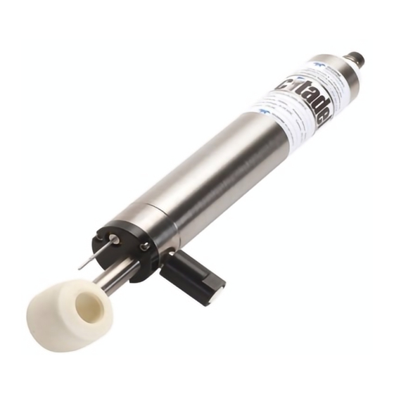
CTD-ES and CTD-ER Technical Manual Main External Components The main external components of the CTD-ES are shown in Figure 1. A single bulkhead con- nector on the lower end cap provides either RS-232 or RS-485 communications and inputs ex- ternal power. The conductivity, temperature, and pressure sensors are located on the top end cap. -
Page 11: Ctd-E Options
CTD-ES and CTD-ER Technical Manual CTD-E Options Depth Rating – CTD-E units are available with the following depth rating: 500 meter (Delrin housing) or 7000 meter (Titanium housing). Pressure Sensor – The pressure sensor is available in the following ranges (in meters): 20, 100, 200, 350, 500, 667, 1000, 2000, 3000 or 7000. -
Page 12: Specifications
CTD-ES and CTD-ER Technical Manual Specifications Below are the general specifications for the CTD-E along with the specifications for the conduc- tivity, temperature, and pressure sensors. NOTE. These specifications are subject to change without notice. General Power requirements: 6–14 VDC @ 120 mA Depth rating: 500 m standard, Delrin housing 7000 m optional, 64-AVL titanium housing... - Page 13 CTD-ES and CTD-ER Technical Manual Temperature Sensor type: Platinum thermometer Range: -2–32°C Accuracy: ±0.002°C Stability: ±0.0005°C/month Resolution: 0.0001°C Response: 150 msec Pressure Sensor type: Precision micro-machined silicon transducer Range: Customer specified Accuracy: ±0.02% of full scale, higher accuracies available Stability: ±0.01% of full scale/month Resolution: 0.001% of full scale...
-
Page 14: Outline Installation Drawings
CTD-ES and CTD-ER Technical Manual Outline Installation Drawings page 8 EAR-Controlled Technology Subject to Restrictions Contained on the Cover Page. - Page 15 CTD-ES and CTD-ER Technical Manual 95F-6001-00 (February 2017) page 9 EAR-Controlled Technology Subject to Restrictions Contained on the Cover Page.
-
Page 16: Unpacking And Setting Up The Ctd-E
CTD-ES and CTD-ER Technical Manual Unpacking and Setting up the CTD-E Before deploying a CTD-E, it must be connected to an available serial port of a computer and configured using CTDAcq. The default serial port for CTDAcq is COM1, and the default baud rate is 9600 bits/sec;... -
Page 17: Installing And Starting Ctdacq
CTD-ES and CTD-ER Technical Manual Most of these items are available from TRDI and are listed with their part numbers in Table 1 below. (See Customer Service for information on how to contact TRDI to order any of these items). Table 1: Optional Items Available from TRDI ITEM... -
Page 18: Communication Interfaces
CTD-ES and CTD-ER Technical Manual Communication Interfaces The CTD-E includes an RS-232 serial interface for configuring and downloading data from the instrument. The instrument was prewired from the factory for RS-232 or RS485 depending on what was specified at the time of order. The serial tag on the instrument identifies which inter- face is installed. -
Page 19: Connecting To The Rs-232 Interface
CTD-ES and CTD-ER Technical Manual Connecting to the RS-232 Interface A CTD-E with an RS-232 interface is shown set up with a laptop computer in Figure 2. To connect a CTD-E with an RS-232 interface to your computer: 1. Disconnect the dummy connector from the bulkhead connector on the instrument and con- nect the test cable. -
Page 20: Connecting To The Rs-485 Interface
CTD-ES and CTD-ER Technical Manual Connecting to the RS-485 Interface A CTD-E with an RS-485 interface is shown set up with a laptop computer in Figure 3. To connect a CTD-E with an RS-485 interface to your computer: 1. Disconnect the dummy connector from the bulkhead connector on the instrument and con- nect the test cable. -
Page 21: Changing The Serial Port
CTD-ES and CTD-ER Technical Manual Changing the Serial Port The default serial port for CTDAcq is COM1. However, any one of four serial ports from COM1 to COM4 can be selected. To change the serial port: 1. Choose Start ➤ Programs ➤ RD Instruments ➤ CTDAcq. CTDAcq starts and the CTDAcq Main window opens. -
Page 22: Checking And Configuring The Ctd-E
CTD-ES and CTD-ER Technical Manual Checking and Configuring the CTD-E After you have connected a CTD-E to your computer’s serial port and have applied power as de- scribed in Connecting the CTD-E to Your Computer, you are ready to check and configure the instrument. -
Page 23: Configuring The Ctd-E
CTD-ES and CTD-ER Technical Manual Figure 5. The Main Window after Checking the CTD-ES Configuring the CTD-E If you are configuring a CTD-E for the first time, it is recommended that you first become famil- iar with the instrument’s operating modes. (See Acquiring, Displaying and Saving Data in Real Time for information on the CTD-E operating modes.) -
Page 24: Figure 6. The Configure Ctd-E Dialog Box
CTD-ES and CTD-ER Technical Manual Once the instrument is configured, the configuration settings can be saved to a file and printed. In addition, the instrument can be configured from a saved file. The CTD-E is configured from the Configure CTD-E dialog box shown in Figure 6. Figure 6. -
Page 25: Selecting The Parameters To Be Output
CTD-ES and CTD-ER Technical Manual Selecting the Parameters to be Output Selecting the parameters to be output by a CTD-E is performed by selecting the corresponding data channels in the Configure CTD-E dialog box. There are two sets of data channels: the Pri- mary Channels and the DC Channels. -
Page 26: Selecting The Ctd-E Sampling Rate
CTD-ES and CTD-ER Technical Manual Figure 7. The DC Channel Setup Dialog Box Selecting the CTD-E Sampling Rate The CTD-E sampling rate is selected in the Sampling Rate area of the Configure CTD-E dialog box. The sampling rate determines the frequency at which the CTD-E measures and outputs the selected parameters. -
Page 27: Setting The Local Time And Date
CTD-ES and CTD-ER Technical Manual Setting the Local Time and Date To set the local time and date: 1. Click Set Time in the Configure CTD-E dialog box. The Enter Local Time and Date dialog box opens: CAUTION. The displayed time and date in the Enter Local Time and Date dialog box is that which was read by CTDAcq from the computer on which CTDAcq is running. -
Page 28: Configuring The Ctd-E From A Saved File
CTD-ES and CTD-ER Technical Manual Figure 8. The Save As Dialog Box for Configuration Files 2. Click the arrow in the Save in drop-down list box and select the folder in which to save the configuration file. 3. In the File name text box enter the name of the file in which to save the configuration set- tings. -
Page 29: Figure 9. The Open Dialog Box For Configuration Files
CTD-ES and CTD-ER Technical Manual Figure 9. The Open Dialog Box for Configuration Files If the file you want to open is not visible, it may be in a different folder than the one shown. In this case, click the arrow in the Look in drop-down list box and select the folder in which the file is located. -
Page 30: Printing The Configuration File
CTD-ES and CTD-ER Technical Manual Printing the Configuration File To print a CTD-E configuration file, choose File ➤ Print Configuration, select the printer to use, and then click OK. An example of a printed CTD-E configuration file is shown in Figure 10. Figure 10. -
Page 31: Acquiring, Displaying And Saving Data In Real Time
CTD-ES and CTD-ER Technical Manual Acquiring, Displaying and Saving Data in Real Time Once you have checked and configured a CTD-E, you can acquire, display, and save the selected parameter data in real time by running the instrument directly from the test cable. See Check- ing and Configuring the CTD-E for instructions on how to check and configure the instrument. -
Page 32: Figure 11. The Ctdacq Acquisition Window
CTD-ES and CTD-ER Technical Manual CTDAcq displays which items are being checked, and the model number, serial number, firmware version, and calibration date of the instrument are displayed in the Instrument Identification Window. 4. If required, configure the instrument as described in Configuring the CTD-E. -
Page 33: Figure 12. The Save As Dialog Box For Data Files
CTD-ES and CTD-ER Technical Manual 6. Choose File ➤ Start Down Cast, or Start Up Cast. The Save As dialog box for data files shown in Figure 12 opens. This dialog box is used to create the file in which to save the parameter data. Figure 12. -
Page 34: Acquiring Real-Time Data In Towed Acquisition Mode
CTD-ES and CTD-ER Technical Manual Figure 13. The Cast Information Window 11. If desired, enter additional cast information in the available text boxes. The cast information can be saved to the header file. 12. Click OK to save the entries and close the Cast Information window, or click Cancel to close the window without saving the entries. -
Page 35: Figure 14. The Ctdacq Acquisition Window-Towed Acquisition
CTD-ES and CTD-ER Technical Manual 1. Connect the CTD-E to your computer and power supply. Choose Start ➤ Programs ➤ RD Instruments ➤ CTDAcq. CTDAcq starts and the CTDAcq Main window opens. 3. Choose Configure ➤ Check Instrument. CTDAcq displays which items are being checked, and the model number, serial number, displayed in the Instrument firmware version, and calibration date of the instrument are... -
Page 36: Acquiring Real-Time Data In Run Continuous Mode
CTD-ES and CTD-ER Technical Manual 9. When you are ready to begin the cast, click Save to create the file in which to save the data and close the dialog box. The instrument begins collecting data. The parameter data are displayed graphically and numerically in the TRDI Acquisition window in real time and saved to the file. -
Page 37: Resetting And Firing A Water Sampler
CTD-ES and CTD-ER Technical Manual 7. Click the arrow in the Save in drop-down list box and select the folder in which to save the parameter data file. 8. In the File name text box enter the name of the file in which to save the data. The extension .dat is added automatically 9. -
Page 38: Setting Up The Graph In The Cast Graphics Display
CTD-ES and CTD-ER Technical Manual time parameter data as a plot when acquiring data in Profile mode. See Acquiring Real-Time Data in Profile Mode. Similarly, the Towed Acquisition display, which includes up to four pres- sure graphs, allows viewing of real-time data as a plot in Towed Acquisition mode. See Acquir- ing Real-Time Data in Towed Acquisition Mode. -
Page 39: Figure 16. The Graph Setup Dialog Box For Data Acquisition
CTD-ES and CTD-ER Technical Manual Figure 16. The Graph Setup Dialog Box for Data Acquisition 5. If you selected the Enable check box, enter the number of scans that are displayed between Auto-Zoom updates in the Update Rate text box. 6. - Page 40 CTD-ES and CTD-ER Technical Manual NOTE. The parameter names shown with an asterisk (*) are calculated parameters based on measured conductivity, temperature and pressure. The calculations are made by CTDAcq. The other parameters shown are the Primary Channel and DC Channel parameters that were selected in the Configure CTD-E dialog box when the instrument was configured.
-
Page 41: Zooming In And Out Of The Cast Graph
CTD-ES and CTD-ER Technical Manual Figure 17. The Cast Graphics Display with Real-Time Plots of Parameter Data Zooming in and Out of the Cast Graph To zoom in on the cast graph, click and hold the left mouse button while drawing a box around the area you want to zoom in on, and then release the mouse button. -
Page 42: Opening The Coordinates Window In The Cast Graphics Display
CTD-ES and CTD-ER Technical Manual Opening the Coordinates Window in the Cast Graphics Display The Coordinates window, which is shown in Figure 18, displays the cast graph coordinates at which the mouse pointer is pointing. As the mouse pointer is moved around the cast graph, the displayed coordinates change accordingly. -
Page 43: Figure 19. The Pressure Graph 1 Setup Dialog Box For Towed Acquisition
CTD-ES and CTD-ER Technical Manual Figure 19. The Pressure Graph 1 Setup Dialog Box for Towed Acquisition 3. Select the Show Graph check box to show the graph. Clear the check box to hide the graph. 4. Select the Use Grid check box if you want to display a grid overlay on the graph. Clear the check box if you do not. -
Page 44: Displaying The Cast Graph In The Towed Acquisition Graphics Display
CTD-ES and CTD-ER Technical Manual 10. Click OK to save the new graph setup and close the Pressure Graph 1 Setup dialog box, or click Cancel to close the dialog box without saving any changes. 11. Except for Step 1, repeat all the steps above for the Pressure Graph 2, Pressure Graph 3 and Pressure Graph 4 graphs, or for only those graphs you want to display. -
Page 45: Opening The Coordinates Window In The Towed Acquisition Graphics Display
CTD-ES and CTD-ER Technical Manual Figure 20. The Towed Acquisition Display with Four Real-Time Pressure Plots of Parameter Data Opening the Coordinates Window in the Towed Acquisi- tion Graphics Display The Coordinates window, which is shown in Figure 18, displays the cast graph coordinates at which the mouse pointer is pointing. -
Page 46: Previewing And Printing Graphs
CTD-ES and CTD-ER Technical Manual To scroll to through the scans, do one of the following: • Click the left arrow to go back one scan; click the right arrow to advance one scan. • Click in the scroll bar to the left of the scroll box to go back 100 scans; click to the right to advance 100 scans. - Page 47 CTD-ES and CTD-ER Technical Manual 2. Select the pressure graph to print, and then click Print. 3. Follow the instructions for your printer to print the graph. To preview and print a pressure graph: 1. Choose File ➤ Print Preview Pressure Graphs. The Print Pressure Graph Setup dialog box opens.
-
Page 48: Ctd-E Maintenance
CTD-ES and CTD-ER Technical Manual CTD-E Maintenance To ensure your CTD-E continues to provide you with accurate data, you should inspect and clean the instrument after each use. This section provides some inspection and cleaning recom- mendations and instructions on how to fill the pressure sensor with oil. Recommended Maintenance Table 2. -
Page 49: Cleaning The Ctd-E
CTD-ES and CTD-ER Technical Manual *The measurement error band of the CTD will widen over time due to component aging. This effect happens regardless of whether or not the instrument is being operated. Due to the stringent accuracy specifications, the effects of drift rapidly become a significant por- tion of the overall instrument error budget. -
Page 50: Oil Fill Procedure And Capillary Tube Installation
Included with your instrument is a capillary tube installation kit. The following procedure will provide guidance to allow you to install the capillary onto the instrument. Should you require further assistance please do not hesitate to contact Teledyne RD Instru- ments and ask to speak to a customer service representative. - Page 51 CTD-ES and CTD-ER Technical Manual Step #1: Place the instrument on a flat surface with the pressure port cavity pointed up. Step #2: Assemble the syringe and insert a small amount of oil from the Nalgene bottle into the syringe. Fill the pressure port cavity to the top with the oil.
- Page 52 CTD-ES and CTD-ER Technical Manual Step #4: Continue threading the assembly until the threads are no longer exposed and the O-ring is seated onto the end cap. Have an absorbent paper towel on hand to clean up any overflow that you may have.
-
Page 53: Appendix A: Measured And Calculated Parameters
CTD-ES and CTD-ER Technical Manual APPENDIX A: Measured and Calculated Parameters Conductivity, temperature, and pressure are measured directly by the CTD-E. In addition, the instrument calculates salinity and sound velocity. Any number of the parameters can be se- lected to output. The time and date on which the parameters are output can also be included with each sample. -
Page 54: Parameters Calculated By Ctdacq
CTD-ES and CTD-ER Technical Manual Parameters Calculated by CTDAcq The parameters calculated by CTDAcq are the following: A single sample of all the selected parameters. Scan (SCAN): The water adiabatic temperature gradient in °C/dbar. Adiabatic Temperature Gradient (*ATG): The water temperature without the effects of pres- Pot (*POT): sure in °C. -
Page 55: Appendix B: Changing The Baud Rate
CTD-ES and CTD-ER Technical Manual APPENDIX B: Changing the Baud Rate The default baud rate for the CTD-E is 9600 bits/sec with one stop bit, eight data bits and no parity. To change the baud rate the CTD-E must be powered and connected to an available se- rial port of the computer. -
Page 56: Appendix C: Connector And Test Cable Wiring
CTD-ES and CTD-ER Technical Manual 6. Click Close to close the Communications Window. 7. Choose Communications ➤ Setup. The Configuration COM Setup dialog box shown in Figure 22 opens. Figure 22. The Configuration COM Setup Dialog Box 8. Select the new baud rate—300, 1200, 9600, or 19200—in the Baudrate area of the Configu- ration COM Setup dialog box. -
Page 57: Bulkhead Connector Wiring
CTD-ES and CTD-ER Technical Manual Bulkhead Connector Wiring Refer to Table 4 for the required connections from the bulkhead connector to the computer, and to Table 5 for the connections from the connector to the power supply. Figure 23 shows the bulkhead connector pin orientation as viewed from the face. -
Page 58: Test Cable Wiring
CTD-ES and CTD-ER Technical Manual Test Cable Wiring If a test cable is not available, you can fabricate your own cable using a pigtail that mates with the CTD-E bulkhead connector. (See Table 3 for the pigtail part number.) Figure 24 shows the pin orientation of the pigtail connector. -
Page 59: Appendix D: Warranty, Liability And Rma Return Procedure
Return Procedure Teledyne RD Instruments Limited Warranty Teledyne RD Instruments (TRDI) guarantees its products to be free from defects in materials and workmanship for a period of one year from the date of shipment. In the event a product malfunctions during this period, TRDI’s obligation is limited to the repair or replacement, at TRDI’s option, of any product returned to the TRDI factory. -
Page 60: Returning Ctds To Trdi For Service
• Open the RMA using the web link: http://adcp.com/support/sendADCP.aspx • Contact Customer Service Administration at rdicsadmin@teledyne.com • Call +1 (858) 842-2700 When requesting a RMA number, please give us the following information: • What is being shipped (include the serial number) •... -
Page 61: European Shipments
In addition, some truck lines may offer equivalent delivery service at a lower cost, depending on the distance to San Diego. Mark the Package(s) Teledyne RD Instruments, Inc. (RMA Number) 14020 Stowe Drive Poway, California 92064 Airport of Destination = San Diego... - Page 62 Non-urgent shipments may be shipped as part of a consolidated cargo shipment to save money. Mark the package(s) as follows: Teledyne RD Instruments, Inc. (RMA Number) 2A Les Nertieres 5 Avenue Hector Pintus...
Need help?
Do you have a question about the Citadel CTD-ES and is the answer not in the manual?
Questions and answers