
Subscribe to Our Youtube Channel
Related Manuals for Teledyne 2150


Summary of Contents for Teledyne 2150
- Page 1 2150 Area Velocity Flow Module and Sensor Installation and Operation Guide Part #60-2003-092 of Assembly #60-2004-038 Copyright © 1999. All rights reserved, Teledyne Isco Revision CE, November 2018...
- Page 3 Règlement sur le materiel brouilleur du Canada. Caution Changes or modifications not expressly approved by the party responsible for compliance (Teledyne Isco) could void your authority to operate the equipment. This equipment should be installed and operated using Isco’s cables, such as the Flowlink Communication Cable or the optional Mod- ule-to-module Cable.
- Page 5 Teledyne ISCO recommends that you read this manual completely before placing the equipment in service. Although Teledyne ISCO designs reliability into all equipment, there is always the possibility of a malfunction. This manual may help in diagnosing and repairing the malfunction.
- Page 7 2150 Area Velocity Module Safety 2150 Area Velocity Module Safety General Warnings Before installing, operating, or maintaining this equipment, it is imperative that all hazards and preventive measures are fully understood. While specific hazards may vary according to location and application, take heed in the following general warnings.
- Page 8 2150 Area Velocity Module Safety The equipment and this manual use symbols used to warn of Hazard Symbols hazards. The symbols are explained below. Hazard Symbols Warnings and Cautions The exclamation point within the triangle is a warning sign alerting you of important instructions in the instrument’s technical reference manual.
-
Page 9: Table Of Contents
1.3 2150 System Overview ........ - Page 10 2150 Area Velocity Flow Module Table of Contents Section 3 Programming 3.1 Section Overview ........... . 3-1 3.2 Flowlink Connections .
- Page 11 1-23 2150 Module Connector Pins ........1-20 2-1 Identifying the 2150 voltage specification ....... 2-3 2-2 Identifying the voltage specification on the DB9 cable .
- Page 12 1-5 Specifications – 2150 Area Velocity Flow Module ......1-17 1-6 Specifications – 2150 Area Velocity Sensor ......1-19 1-7 Specifications –...
-
Page 13: Section 1 Introduction
“lock” in place. Each locking mechanism strongly secures the components and ensures a watertight seal. The flow information from a 2150 can be used to pace an Isco 3700, GLS, or 6700 Series sampler. The connection is made using a 2100 Series Sampler Interface Cable (Isco part #68-2000-014). -
Page 14: Applications
Sensor. Additionally, the AV Module can measure its input AV Module voltage – a service feature. The 2150 is designed to provide durable operation with only a minimal amount of routine maintenance, all of which may be performed in the field. Typically, the AV Module and its AV... -
Page 15: Velocity
• Two-term Polynomial Equations • Flumes • Weirs Often the Model 2150 Area Velocity Flow Module is chosen for applications where a primary device is not available, nor is it practical to install a primary device. Therefore, area velocity is usually the conversion method of choice. -
Page 16: Input Voltage
2150 Area Velocity Flow Module Section 1 Introduction Secondary rates are used to log data at a different rate when a user-defined condition exists. For example, a secondary rate can be used to increase the level and velocity data storage rate when level is greater than or equal to a point of interest. -
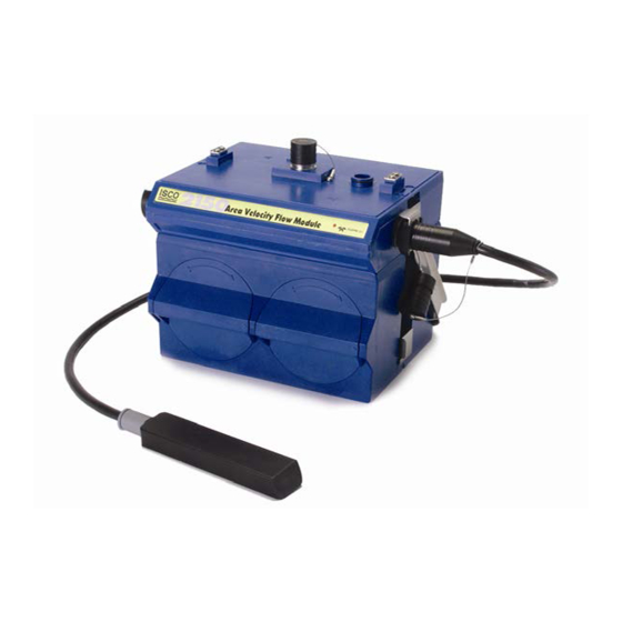
Page 17: Component Identification
2150 Area Velocity Flow Module Section 1 Introduction 1.4 Component The components of the 2150 Module, area velocity sensor, and 2191 Battery Module are shown in Figures 1-2 through 1-3. Identification Items referenced in the figures are briefly discussed in the tables below. -
Page 18: Battery Module
2150 Area Velocity Flow Module Section 1 Introduction 1.4.1 Battery Module Figures 1-2 and 1-3 identify key components of the model 2191 Battery Module. Figure 1-2 Battery Module components, top view Table 1-2 Battery Module Components - Top View Item No. -
Page 19: Battery Module Components, Bottom View
2150 Area Velocity Flow Module Section 1 Introduction Figure 1-3 Battery Module components, bottom view Table 1-3 Battery Module Components - Bottom View Item No. Description Fig. 1-3 Communication connector Connector plug Connector plug holder Latch... -
Page 20: Area Velocity Sensor Parts
2150 Area Velocity Flow Module Section 1 Introduction Figure 1-4 2150 Area Velocity Sensor Parts Table 1-4 2150 Area Velocity Sensor Parts and Descriptions Item No. Name Description Fig. 1-4 Connector Cap Protects the connector. When the connector is not in use, this cap must be in place to prevent damage to the connector pins and reference air tubing. -
Page 21: Latches
2150 Area Velocity Flow Module Section 1 Introduction 1.5 Latches Latches must be operated to stack and unstack the modules. Take a moment to familiarize yourself with operating the latches. The latch is operated by pushing on one of the sides — the right side to unlock, and the left side to lock. -
Page 22: Communication Connectors
2150 Area Velocity Flow Module Section 1 Introduction 1.6 Communication When a communication connector is not in use, the con- nector should always be capped (Figures 1-6 and 1-8). The Connectors cap will seal the connector to prevent corrosion, prevent moisture from entering the unit, and improve communications. -
Page 23: Connecting The Sensor
Section 1 Introduction Figure 1-9 Flow Module - Lower connector, unplugged 1.7 Connecting the Sensor To connect the Area Velocity Sensor to the 2150 Flow Module, follow steps in Figures 1-10 and 1-11. 1. Prepare the 2150’s sensor connector by removing the cap. -
Page 24: Installing The Batteries
2150 Area Velocity Flow Module Section 1 Introduction 1.8 Installing the Batteries The Battery Module requires two lantern batteries. The figures below show a 6 VDC alkaline battery. Rechargeable 6 VDC lead-acid batteries are also available for the module. To install the batteries, follow the instructions in Figures 1-12 through 1-15. -
Page 25: Battery Module - Closing The Door
2150 Area Velocity Flow Module Section 1 Introduction W h i l e h o l d i n g t h e d o o r i n y o u r r i g h t hand, align the marks and insert the door. -
Page 26: Stacking Modules
2150 Area Velocity Flow Module Section 1 Introduction 1.9 Stacking Modules To stack a 2150 Flow Module on a 2191 Battery Module, follow the instructions in Figures 1-16 through 1-22. Unlock the latch to release the connector plug. Figure 1-16 Flow Module - Unlocking the latch Pull the plug out of the con- nector. -
Page 27: Flow Module - Pushing Plug Into Holder
2150 Area Velocity Flow Module Section 1 Introduction Push the plug into the holder. Figure 1-18 Flow Module - Pushing plug into holder On the Battery Module, uncap the connector. Store the cap on the holder. Figure 1-19 Battery Module - uncapping the connector... -
Page 28: Battery Module - Inserting The Handle
2150 Area Velocity Flow Module Section 1 Introduction P l a c e t h e h a n d l e o n t h e Battery Module. The handle must rest towards the back of the module, otherwise its... -
Page 29: Technical Specifications
7 to 26 VDC, 100 mA typical at 12 VDC, 1 mA standby Note Earlier versions of the 2150, as well as some other system compo- nents including cables, have lower voltage limits and cannot be con- nected in systems powered by more than 16.6 VDC. Refer to Section 2.2.2 for complete information. - Page 30 2150 Area Velocity Flow Module Section 1 Introduction Table 1-5 Specifications – 2150 Area Velocity Flow Module (Continued) Typical Battery Life (one mod- Data Storage Interval Alkaline Batteries Lead-Acid Batteries ule) 15 minutes 15 months 2.5 months 5 minutes 8 months 1.5 months...
-
Page 31: Specifications - 2150 Area Velocity Sensor
2150 Area Velocity Flow Module Section 1 Introduction Table 1-6 Specifications – 2150 Area Velocity Sensor 0.75 1.31 6.00 in. 1.9 3.3 15.2 cm Size (HWD) Cable Length 394 in. 10 m Cable Diameter 0.37 in. 0.9 cm Weight (including cable) 2.1 lbs... -
Page 32: Specifications - 2191 Battery Module
Capacity Alkaline Lantern Batteries 25 Ahrs Lead-acid Lantern Batteries 5 Ahrs Communications Port (upper connector shown) Figure 1-23 2150 Module Connector Pins Table 1-8 AV Module Connector Pins Name Description LONA Neuron differential transceiver Data A LONB Neuron differential transceiver Data B... -
Page 33: Section 2 Preparation And Installation
When the system arrives, inspect the outside packing for any damage. Then carefully inspect the contents for damage. If there Instructions is damage, contact the delivery company and Teledyne Isco (or its agent) immediately. WARNING If there is any evidence that any items may have been damaged in shipping, do not attempt to install the unit. -
Page 34: Safety
2.2.2 System Power 2150 modules currently sold can be powered by 7 to 26 volts. Earlier units, as well as some other 2100 system components, are limited to a maximum of 16.6 volts (12 volts typical). The voltage specification is printed on the serial tag located on the back of the module (refer to Figure 2-1). -
Page 35: Identifying The 2150 Voltage Specification
2150 Area Velocity Flow Module Section 2 Preparation and Installation Figure 2-1 Identifying the 2150 voltage specification The module crown connector on the earlier RS-232 DB9 digital communication cable (part #60-2004-046) is unmarked. The con- nector on the 26-volt cable has a serial tag specifying the higher voltage (refer to Figure 2-2). -
Page 36: Preparing For Installation
Installation 2.3.1 Locating the Site The 2150 Flow Module is designed to measure flow in open channels with or without a primary device. A primary device is a hydraulic structure, such as a weir or a flume that modifies a channel so there is a known relationship between the liquid level and the flow rate. -
Page 37: Installation Procedures
2150 Area Velocity Flow Module Section 2 Preparation and Installation materials that can withstand harsh environments. However, con- tinual exposure to UV light, or periodic submersion should be avoided to extend the life of the components. Typically, the AV Module is suspended inside a manhole. Sus-... -
Page 38: Inspect The Desiccant - Battery Module
2150 Area Velocity Flow Module Section 2 Preparation and Installation Battery Connector Battery Carrier Door Figure 2-3 Installing a Battery 2.4.2 Inspect the Desiccant – A humidity indicator is mounted inside each battery cap on the Battery Module Battery Module. The humidity indicators have regions that display 20, 30, and 40 percent humidity levels. -
Page 39: Assembling A System (Shown: 2 Flow Modules With 1 Battery Module)
2150 Area Velocity Flow Module Section 2 Preparation and Installation convenient if you place the Battery Module at the bottom of the stack. This keeps the heavier items lower in the stack making it easier to transport or store. Other modules may be attached to this stack to increase the site’s functions. -
Page 40: Installing The Modules
In manholes, the modules are often secured to a ladder rung, or suspended from a spreader bar. Teledyne Isco’s Customer Service Department or your local representative can assist you with installation options. -
Page 41: Connecting The Av Sensor
2150 Area Velocity Flow Module Section 2 Preparation and Installation Note To protect the AV Module and sensor, the hydrophobic filter seals off the reference air line when it is exposed to excessive moisture. When sealed, the filter prevents irreparable damage, yet may cause the level readings to drift. -
Page 42: Installing The Av Sensor
2150 Area Velocity Flow Module Section 2 Preparation and Installation 3. Align and insert the connector. The sensor release will “click” when the sensor connector is fully seated. 4. Connect the two caps together. Connector Clip Caps Figure 2-5 Connecting the AV Sensor 2.4.7 Installing the AV... -
Page 43: Program The Module
Do not kink the cable or overtighten the plastic ties while securing the cable. Secure the cable - Teledyne Isco recommends that you secure the cable in place. Tying off the cable can often prevent lost equipment if excessive flow dislodges the sensor and its mounting. -
Page 44: Basic Installation Checklist
As a review, the following steps may be used as a guide to install Checklist a 2150 Module at a basic site. In this example, a basic site is a single AV Module and AV Sensor, and a Battery Module. Your steps may differ if you have selected an alternative power source, or if you are installing additional modules. -
Page 45: Site Example
A communication cable connects the computer and site. The cable supports the data transfers between the two. Note Earlier versions of the 2150, as well as some other system components including cables, have lower voltage limits and cannot be connected in systems powered by more than 16.6 VDC. -
Page 46: Typical Round-Pipe Installation
2150 Area Velocity Flow Module Section 2 Preparation and Installation Computer running Flowlink Communication Cable Spreader Bar AV Module and Battery Module Street level Installation Ring Release Strap AV Sensor Cable Street level Installation Ring AV Sensor Figure 2-6 Typical Round-pipe Installation... -
Page 47: Mounting Rings
For pipes up to 15" (38 cm) in diameter, stainless steel self-expanding mounting rings (Spring Rings) are available. For pipes larger than 15" in diameter, Teledyne Isco offers the Scissors Rings (Universal Mounting Rings). Area velocity sensors can also be installed using primary measuring devices. - Page 48 2150 Area Velocity Flow Module Section 2 Preparation and Installation Attach the AV sensor to the ring either by using two 4-40 coun- Attaching the Sensor to the Ring tersink screws or by snapping the optional probe carrier to the ring.
-
Page 49: Scissors Mounting Ring
2150 Area Velocity Flow Module Section 2 Preparation and Installation 2.6.2 Scissors Mounting For pipes larger than 15" in diameter, Teledyne Isco offers the Ring adjustable Scissors Ring (also known as the Universal Mounting Ring). This device consists of two or more metal strips that lock together with tabs to form a single assembly. -
Page 50: Completing The Av Sensor Installation
2150 Area Velocity Flow Module Section 2 Preparation and Installation Scissors Assembly Extensions Base Section Tightening the scissors assembly expands the ring to press firmly against the pipe wall, securing the ring. Figure 2-8 Scissors Ring adjustment To prevent debris from catching on the probe cable, it is important to attach the cable to the mounting ring so it offers as little resistance to the flow as possible. - Page 51 2150 Area Velocity Flow Module Section 2 Preparation and Installation CAUTION Under no circumstances should you leave any extra length of sensor cable dangling freely in the flow stream where it could trap debris or become tangled. Use gloves and eye protection when assembling and installing the rings in a pipe.
- Page 52 2150 Area Velocity Flow Module Section 2 Preparation and Installation 2-20...
-
Page 53: Section 3 Programming
2150 Area Velocity Flow Module Section 3 Programming 3.1 Section Overview This section describes how to set up the operation of a 2150 Module using Isco’s Flowlink for Windows software. Detailed Flowlink instructions are beyond the scope of this Flowlink Help manual. -
Page 54: Communication Resolution
2150 Area Velocity Flow Module Section 3 Programming An easy way to begin Flowlink communications with the site is to Quick Connect. As a default Flowlink setting, the Quick Connect dialog box opens when you start Flowlink. Click on the large 2100 Instruments button to connect. -
Page 55: Level
2150 Area Velocity Flow Module Section 3 Programming These five program settings directly affect the data collection. Incorrect settings may introduce errors in the measured data, many of which may prove to be difficult to correct afterwards. You should also check the Data Storage Rates while you are Data Storage Settings reviewing the program settings. -
Page 56: Zero Level Offset
2150 Area Velocity Flow Module Section 3 Programming Figure 3-2 Preferred Measurement Location Do not measure the level and channel dimensions right at the sensor, as the sensor and the mounting ring may cause a slight “jump” or localized rise in the level. At very low levels and high velocities, this jump in the liquid surface may become quite sig- nificant. -
Page 57: No Velocity Data And Flow Rates
2150 Area Velocity Flow Module Section 3 Programming Note Do not confuse the circumferential distance between true zero and the location of the AV Sensor with the vertical distance (height). If you install the AV Sensor at the true zero level of the pipe or channel, you would enter “0”... -
Page 58: Flow Conversion
2150 Area Velocity Flow Module Section 3 Programming 3.3.5 Flow Conversion The AV Module is capable of determining flow rates using either area velocity conversion or level-to-flow rate conversion. Table 3-1 lists the available flow conversion methods. The AV Module is capable of calculating and storing any two con- version methods simultaneously. -
Page 59: Silt Level
2150 Area Velocity Flow Module Section 3 Programming If the selected flow conversion requires channel dimensions, actual channel measurements should be taken. Channel mea- surements are preferred over nominal values. Significant errors may be introduced if your measurements are inaccurate. The example below illustrates the importance of accurate measure- ments. -
Page 60: Site Name
2150 Area Velocity Flow Module Section 3 Programming 3.3.8 Site Name The modules are shipped with default names so that they can immediately begin to communicate with Flowlink. You can change the site name to a more descriptive name on the Site Info tab in Flowlink. -
Page 61: Section 4 Modbus Output Protocol
2150 Area Velocity Flow Module Section 4 Modbus Output Protocol Sections 4.1 through 4.5 give an overview of the basic capabilities and operation of Modbus protocol as it applies to Isco 2100 Series flow modules. For a Glossary of Terms and Common Acronyms, see sections 4.4 and 4.5. -
Page 62: Establishing Communication
2150 Area Velocity Flow Module Section 4 Modbus Output Protocol By accessing these registers you can obtain the current value of whatever parameter you desire. The reading(s) can then be dis- played or stored wherever you designate as a destination; for example, a process control computer. -
Page 63: Configurations
2150 Area Velocity Flow Module Section 4 Modbus Output Protocol 4.3 Configurations A variety of configurations can be made with Modbus, either through direct connection or through a modem. In the example shown in Figure 4-1, you are direct-connecting a... -
Page 64: Glossary Of Terms
2150 Area Velocity Flow Module Section 4 Modbus Output Protocol 5. OPC connects to the 2150 stack through the cable (direct connection), takes register data from the specified 2150, and populates the OPC server's holding index. 6. Process Control takes data from the OPC server's holding index and gives data to the user. -
Page 65: Common Acronyms
2150 Area Velocity Flow Module Section 4 Modbus Output Protocol SCADA systems can be relatively simple, such as one that mon- itors the environmental conditions of a small office building, or very complex, such as a system that monitors all the activity in a nuclear power plant or a municipal water system. - Page 66 2150 Area Velocity Flow Module Section 4 Modbus Output Protocol...
-
Page 67: Section 5 Maintenance
2150 Area Velocity Flow Module Section 5 Maintenance 5.1 Maintenance This section explains the maintenance requirements of the 2150 Overview Module and its sensor. The 2100 Series system is designed to perform reliably in adverse conditions with a minimal amount of routine service requirements. -
Page 68: Batteries
2150 Area Velocity Flow Module Section 5 Maintenance 5.3 Batteries Input voltage can be monitored while you are connected to the AV Module with Flowlink. The AV Module also can record Input Voltage readings to closely track the power consumption. Keep in mind that battery discharge rates vary widely depending on the configuration of your system and its operating environment. -
Page 69: Replacing The Desiccant: Battery Module
2150 Area Velocity Flow Module Section 5 Maintenance 5.4.2 Replacing the A bag of desiccant is located inside each of the battery caps Desiccant: Battery behind a retaining plate. To replace the desiccant: Module 1. Loosen the two mounting screws that secure the metal retaining plate. -
Page 70: Channel Conditions
“as-needed.” Sections 5.6.1 through 5.6.3 describe these activities. 5.6.1 Hydrophobic Filter If the 2150 is in a humid location or submerged, a hydrophobic filter prevents water from entering the desiccant cartridge and reference line. Any amount of water will plug the filter and it must be rinsed with clean water and allowed to dry, or replaced so that the reference line can be reliably ventilated. -
Page 71: Sensor Cable Inspection
IscoService@teledyne.com 5.7.1 Diagnostics As a troubleshooting aid, many module functions can generate a diagnostic file. With the assistance of a Teledyne Isco Technical Service Representative, the diagnostic files can often be used to isolate a problem. - Page 72 2150 Area Velocity Flow Module Section 5 Maintenance To view a diagnostic file, connect to the site with Flowlink. View the measurement tab of the suspect function and click on the Diagnostics... button. The module then generates the file and sends it to Flowlink where it is displayed as a text report.
-
Page 73: Appendix A Replacement Parts
Replacement parts are called out in illustrations in this section. Reference the call-outs in the accompanying tables to determine Diagrams and Listings the part number for the item. Replacement parts can be purchased by contacting Teledyne Isco’s Customer Service Department. Teledyne Isco Customer Service Department P.O. - Page 74 2150 Area Velocity Flow Module Appendix A Replacement Parts...
- Page 75 2150 Area Velocity Flow Module Appendix A Replacement Parts...
- Page 76 2150 Area Velocity Flow Module Appendix A Replacement Parts...
- Page 77 2150 Area Velocity Flow Module Appendix A Replacement Parts...
- Page 78 2150 Area Velocity Flow Module Appendix A Replacement Parts...
- Page 79 2150 Area Velocity Flow Module Appendix A Replacement Parts...
- Page 80 2150 Area Velocity Flow Module Appendix A Replacement Parts...
- Page 81 2150 Area Velocity Flow Module Appendix A Replacement Parts...
- Page 82 2150 Area Velocity Flow Module Appendix A Replacement Parts A-10...
-
Page 83: Appendix B Accessories
B.2 General Accessories 2150 A/V Sensor ......60-2004-135 Tubing, Reference Air Extension, 10 ft... . 60-2003-104 Alkaline Lantern Battery . -
Page 84: Av Sensor Mounting Accessories
2150 Area Velocity Flow Module Appendix B Accessories B.4 AV Sensor Mounting The 2150 Area Velocity Sensor can be installed using Isco’s installation systems listed below. A Low Profile Carrier is Accessories optional when attaching the AV Sensor to any system listed below. -
Page 85: Appendix C Material Safety Data Sheets
Appendix C Material Safety Data Sheets C.1 Overview This appendix to the manual provides Material Safety Data Sheets for the desiccant used by the 2150 Area Velocity Module and 2191 Battery Module. Teledyne Isco cannot guarantee the accuracy of the data. Specific questions regarding the use and handling of the products should be directed to the manufacturer listed on the MSDS. - Page 86 2150 Area Velocity Flow Module Appendix C Material Safety Data Sheets 101 Christine Drive Belen, New Mexico 87002 Phone: (505) 864-6691 Fax: (505) 861-2355 ISO 9002 MATERIAL SAFETY DATA SHEET -- September 28, 1998 ® SORB-IT Packaged Desiccant SECTION I -- PRODUCT IDENTIFICATION...
- Page 87 2150 Area Velocity Flow Module Appendix C Material Safety Data Sheets 101 Christine Drive Belen, New Mexico 87002 Phone: (505) 864-6691 Fax: (505) 861-2355 ISO 9002 MATERIAL SAFETY DATA SHEET -- September 28, 1998 ® SORB-IT Packaged Desiccant SECTION IV -- FIRE EXPLOSION DATA Fire and Explosion Hazard - Negligible fire and explosion hazard when exposed to heat or flame by reaction with incompatible substances.
- Page 88 2150 Area Velocity Flow Module Appendix C Material Safety Data Sheets 101 Christine Drive Belen, New Mexico 87002 Phone: (505) 864-6691 Fax: (505) 861-2355 ISO 9002 MATERIAL SAFETY DATA SHEET -- September 28, 1998 ® SORB-IT Packaged Desiccant NOTE TO PHYSICIAN: This product is a desiccant and generates heat as it adsorbs water.
- Page 89 2150 Area Velocity Flow Module Appendix C Material Safety Data Sheets 101 Christine Drive Belen, New Mexico 87002 Phone: (505) 864-6691 Fax: (505) 861-2355 ISO 9002 MATERIAL SAFETY DATA SHEET -- September 28, 1998 ® SORB-IT Packaged Desiccant SECTION IX -- SPECIAL PRECAUTIONS Avoid breathing dust and prolonged contact with skin.
- Page 90 2150 Area Velocity Flow Module Appendix C Material Safety Data Sheets...
- Page 91 2150 Area Velocity Flow Module Appendix C Material Safety Data Sheets...
- Page 92 2150 Area Velocity Flow Module Appendix C Material Safety Data Sheets...
- Page 93 2150 Area Velocity Flow Module Appendix C Material Safety Data Sheets...
- Page 94 2150 Area Velocity Flow Module Appendix C Material Safety Data Sheets C-10...
- Page 95 2150 Area Velocity Flow Module Appendix C Material Safety Data Sheets C-11...
- Page 96 2150 Area Velocity Flow Module Appendix C Material Safety Data Sheets C-12...
-
Page 97: Safety Considerations
The second section deals with the special problem of hazardous gases found in sewers. The 2150 has not been approved for use in hazardous locations as defined by the National Electrical Code. D.2 Practical Safety The following procedures are those used by Black &... -
Page 98: Adverse Atmospheres
2150 Area Velocity Flow Module Appendix D Safety Information number of personnel. Hasty actions may result in serious injuries. Time spent in the manhole should be kept to a minimum. D.2.3 Adverse Atmospheres [Refer to Table D-1, Hazardous Gases, at the end of this appendix.] Before workers enter a manhole, tests should be made... -
Page 99: Traffic Protection
2150 Area Velocity Flow Module Appendix D Safety Information D.2.5 Traffic Protection In addition to traffic cones, markers, warning signs, and barri- cades, a vehicle or a heavy piece of equipment should be placed between the working area and oncoming traffic. Flashing warning signals should be used to alert drivers and pedestrians. -
Page 100: Lethal Atmospheres In Sewers
2150 Area Velocity Flow Module Appendix D Safety Information Gas detectors Safety vests Gas masks Waders” D.3 Lethal Atmospheres in The following is an article written by Dr. Richard D. Pomeroy, and published in the October 1980 issue of Deeds & Data of the Sewers WPCF. - Page 101 2150 Area Velocity Flow Module Appendix D Safety Information unimportant, but they rarely measure H S. Death has occurred where it is unlikely that there was any measurable reduction in the oxygen concentration. Waste water containing 2 mg per liter of dissolved sulfide, and at a pH of 7.0, can produce, in a chamber...
-
Page 102: Hazardous Gases
2150 Area Velocity Flow Module Appendix D Safety Information determine percent oxygen in the air. There is a danger that the result will influence a man's thinking about the seriousness of the real hazards. Most important, use ample ventilation, and do not enter a potentially hazardous structure except in a good safety harness with two men at the top who can lift you out.”... - Page 103 2150 Area Velocity Flow Module Appendix D Safety Information Table D-1 Hazardous Gases (Continued) Specific Explosive Likely Max. Safe Simplest and Gravity Safe 60 Range (% by Location Most Chemical Common Physiological 8 Hour Cheapest or Vapor Min. vol. in air)
- Page 104 2150 Area Velocity Flow Module Appendix D Safety Information Table D-1 Hazardous Gases (Continued) Specific Explosive Likely Max. Safe Simplest and Gravity Safe 60 Range (% by Location Most Chemical Common Physiological 8 Hour Cheapest or Vapor Min. vol. in air)
- Page 105 2150 Area Velocity Flow Module Appendix D Safety Information Table D-1 Hazardous Gases (Continued) Specific Explosive Likely Max. Safe Simplest and Gravity Safe 60 Range (% by Location Most Chemical Common Physiological 8 Hour Cheapest or Vapor Min. vol. in air)
- Page 106 2150 Area Velocity Flow Module Appendix D Safety Information D-10...
- Page 107 Compliance Statements Name and amount of Hazardous Substances or Elements in the product Hazardous Substances or Elements Component Name (Pb) (Hg) (Cd) (Cr(VI)) (PBB) (PBDE) Circuit Boards Name and amount of Hazardous Substances or Elements in the product O: Represent the concentration of the hazardous substance in this component’s any homogeneous pieces is lower than the ST/ standard limitation.
- Page 109 Name and amount of Hazardous Substances or Elements in the product Hazardous Substances or Elements Component Name (Pb) (Hg) (Cd) (Cr(VI)) (PBB) (PBDE) Circuit Boards Name and amount of Hazardous Substances or Elements in the product O: Represent the concentration of the hazardous substance in this component’s any homogeneous pieces is lower than the ST/ standard limitation.
- Page 113 DECLARATION OF CONFORMITY Application of Council Directive: 89/336/EEC – The EMC Directive 73/23/EEC – The Low Voltage Directive Manufacturer's Name: Teledyne Isco, Inc. Manufacturer's Address: 4700 Superior, Lincoln, Nebraska 68504 USA Mailing Address: P.O. Box 82531, Lincoln, NE 68501 Equipment Type/Environment:...
- Page 114 Warranty...
- Page 115 The warrantor is Teledyne Isco, 4700 Superior, Lincoln, NE 68504, U.S.A. *This warranty applies to the USA and countries where Teledyne Isco does not have an authorized dealer. Customers in countries outside the USA, where Teledyne Isco has an authorized dealer, should contact their Teledyne Isco dealer for warranty service.
Need help?
Do you have a question about the 2150 and is the answer not in the manual?
Questions and answers