Sign In
Upload
Manuals
Brands
Teledyne Manuals
Accessories
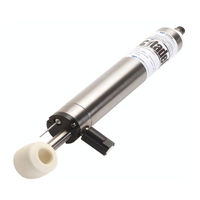
Citadel CTD-ER
Teledyne Citadel CTD-ER Manuals
Manuals and User Guides for Teledyne Citadel CTD-ER. We have
1
Teledyne Citadel CTD-ER manual available for free PDF download: Technical Manual
Teledyne Citadel CTD-ER Technical Manual (62 pages)
High Accuracy Real Time Conductivity, Temperature, and Depth Profiler
Brand:
Teledyne
| Category:
Accessories
| Size: 2 MB
Table of Contents
Table of Contents
3
Introduction
7
Maximum Operating Depth
7
System Configuration Requirements
8
Pull-Down Menus
8
Customer Service
9
Main External Components
10
Figure 1. the Location of the CTD-ES Main External Components
10
CTD-E Options
11
Specifications
12
Outline Installation Drawings
14
Unpacking and Setting up the CTD-E
16
Unpacking the CTD-E
16
Standard Items
16
Optional Items
16
Installing and Starting Ctdacq
17
Installing Ctdacq
17
Starting Ctdacq
17
Communication Interfaces
18
RS-232 Interface
18
RS-485 Interface
18
Connecting the CTD-E to Your Computer
18
Connecting to the RS-232 Interface
19
Figure 2. CTD-ES Setup-With RS-232 Interface
19
Connecting to the RS-485 Interface
20
Figure 3. CTD-ES Setup-With RS-485 Interface
20
Changing the Serial Port
21
Figure 4. the Configuration COM Setup Dialog Box
21
Checking and Configuring the CTD-E
22
Checking the CTD-E
22
Configuring the CTD-E
23
Figure 5. the Main Window after Checking the CTD-ES
23
Figure 6. the Configure CTD-E Dialog Box
24
Selecting the Parameters to be Output
25
Figure 7. the DC Channel Setup Dialog Box
26
Selecting Scaled Output
26
Selecting the CTD-E Sampling Rate
26
Selecting to Average Collected Data
26
Selecting to Output Data on the RS-232 Serial Port
26
Setting the Local Time and Date
27
Saving the CTD-E Configuration to a File
27
Configuring the CTD-E from a Saved File
28
Figure 8. the Save as Dialog Box for Configuration Files
28
Figure 9. the Open Dialog Box for Configuration Files
29
Printing the Configuration File
30
Figure 10. Example CTD-E Configuration File Printout
30
Acquiring, Displaying and Saving Data in Real Time
31
Real-Time Operating Modes
31
Acquiring Real-Time Data in Profile Mode
31
Figure 11. the Ctdacq Acquisition Window
32
Figure 12. the Save as Dialog Box for Data Files
33
Acquiring Real-Time Data in Towed Acquisition Mode
34
Figure 13. the Cast Information Window
34
Figure 14. the Ctdacq Acquisition Window-Towed Acquisition
35
Acquiring Real-Time Data in Run Continuous Mode
36
Resetting and Firing a Water Sampler
37
Setting up the Graphics Displays
37
Figure 15. the CTD-E Run Continuous Mode Window
37
Setting up the Graph in the Cast Graphics Display
38
Figure 16. the Graph Setup Dialog Box for Data Acquisition
39
Figure 17. the Cast Graphics Display with Real-Time Plots of Parameter Data
41
Listing the Data with the Cast Graph
41
Zooming in and out of the Cast Graph
41
Figure 18. the Coordinates Window
42
Opening the Coordinates Window in the Cast Graphics Display
42
Setting up the Graphs in the Towed Acquisition Graphics Display
42
Figure 19. the Pressure Graph 1 Setup Dialog Box for Towed Acquisition
43
Displaying the Cast Graph in the Towed Acquisition Graphics Display
44
Setting up the Cast Graph from the Towed Acquisition Graphics Display
44
Figure 20. the Towed Acquisition Display with Four Real-Time Pressure Plots of Parameter Data
45
Listing the Data in the Towed Acquisition Graphics Display
45
Opening the Coordinates Window in the Towed Acquisition Graphics Display
45
Scrolling through the Pressure Graph Scans
45
Zooming in and out of the Cast Graph in the Towed Acquisition Graphics Display
45
Previewing and Printing Graphs
46
Previewing and Printing the Cast Graph
46
Previewing and Printing the Pressure Graphs
46
CTD-E Maintenance
48
Recommended Maintenance
48
Cleaning the CTD-E
49
Oil Fill Procedure and Capillary Tube Installation
50
APPENDIX A: Measured and Calculated Parameters
53
Parameters Measured by the Instrument
53
Parameters Calculated by the Instrument
53
Parameters Calculated by Ctdacq
54
APPENDIX B: Changing the Baud Rate
55
Figure 21. the Communications Window
55
APPENDIX C: Connector and Test Cable Wiring
56
Figure 22. the Configuration COM Setup Dialog Box
56
Bulkhead Connector Wiring
57
Figure 23. Bulkhead Connector-Face View Female
57
Test Cable Wiring
58
Figure 24. Pigtail Connector for Bulkhead Connector-Face View Male
58
APPENDIX D: Warranty, Liability and RMA Return Procedure
59
Teledyne RD Instruments Limited Warranty
59
Liability
59
Returning Ctds to TRDI for Service
60
Domestic Shipments
60
European Shipments
61
Advertisement
Advertisement
Related Products
Teledyne Citadel CTD-ES
Teledyne Everywhereyoulook CCD261-04
Teledyne CP030A
Teledyne c1940
Teledyne c1930
Teledyne c2020
Teledyne c2450
Teledyne CA-GENM-TSM00
Teledyne CP-6302-31-I
Teledyne CM-6405-11-I
Teledyne Categories
Measuring Instruments
Analytical Instruments
Digital Camera
Test Equipment
Laboratory Equipment
More Teledyne Manuals
Login
Sign In
OR
Sign in with Facebook
Sign in with Google
Upload manual
Upload from disk
Upload from URL