Table of Contents
Advertisement
Quick Links
Advertisement
Table of Contents

Related Manuals for Teledyne 452


Summary of Contents for Teledyne 452
- Page 1 MODEL 452 PROCESS OZONE SENSOR User Manual ©2017Teledyne API (TAPI) www.teledyne-api.com 9970 Carroll Canyon Road San Diego, CA 92131-1106 Toll free: 800-324-5190 Phone: +1 858-657-9800 Fax: +1 858-657-9816 mail: api-sales@teledyne.com Copyright 2017 02852F DCN7659 Teledyne API 21 November 2017...
- Page 3 Teledyne API M452 Ozone Sensor Instruction Manual, 02852F DCN7659 SAFETY MESSAGES NOTE The only user-serviceable part in the Model 452 is the lamp, which can be adjusted or replaced; however, the cautionary safety measures provided in this manual must be followed. For all other service, call TAPI Technical Support.
-
Page 4: Table Of Contents
Teledyne API M452 Ozone Sensor Instruction Manual, 02852F DCN7659 TABLE OF CONTENTS SAFETY MESSAGES ............................. I TABLE OF CONTENTS ..........................II LIST OF FIGURES ............................II LIST OF TABLES ............................III WARRANTY POLICY ..........................IV 1 PRODUCT DESCRIPTIONS ........................1-1 1.1 M452 P... - Page 5 Teledyne API M452 Ozone Sensor Instruction Manual, 02852F DCN7659 4-1: E ......................4-1 IGURE LECTRICAL ONNECTIONS 4-2: D ....................4-3 IGURE IGITAL UTPUT ONNECTIONS 5-1. C ......................5-2 IGURE OVER SSEMBLY CREWS 5-2. UV L ....................... 5-2 IGURE RIENTATION 5-3. V .....................
-
Page 6: Warranty Policy
Product Return All units or components returned to Teledyne API should be properly packed for handling and returned freight prepaid to the nearest designated Service Center. After the repair, the equipment will be returned, freight prepaid. -
Page 7: Product Descriptions
1 Product Descriptions 1.1 M452 Process Ozone Sensor The Teledyne API M452 is a microprocessor-based sensor for measuring the concentration of gaseous ozone in processes such as semiconductor wafer fabrication, water treatment, and ozone research. The M452 can be used as a full flow process sensor or as a sensor to monitor a small flow of gas diverted from a process stream. -
Page 8: Specifications
Teledyne API M452 Ozone Sensor Instruction Manual, 02852F DCN7659 2 Specifications Note: All specifications contained herein are subject to change without notice. Please contact Teledyne API to obtain the current specifications. 2.1 Mechanical Specifications Figure 2-1: M452A High Purity Ozone Sensor Weight: 2.8 lbs. -
Page 9: Performance Specifications
Teledyne API M452 Ozone Sensor Instruction Manual, 02852F DCN7659 2.2 Performance Specifications ±1% of Full Scale. Accuracy: Repeatability: 1% of Full Scale Response Time: 2 sec. To 95% Zero Drift: 1% Full Scale/month (non – cumulative) 2.3 Operating Limits Measurement Range:... -
Page 10: Pressure Drop
Teledyne API M452 Ozone Sensor Instruction Manual, 02852F DCN7659 2.6 Pressure Drop Figure 2-2 below shows the approximate pressure drop from the inlet fitting to the outlet fitting as a function of volumetric flow rate. Pressure Drop vs. Flow 1.000 y = 0.0008x... -
Page 11: Theory Of Operation
The detection of ozone molecules is based on absorption of 254 nm UV light due to an internal electronic resonance of the O molecule. The Model 452 uses a mercury lamp constructed so that a large majority of the light emitted is at the 254 nm wavelength. Light from the lamp shines through an absorption cell through which the sample gas being measured is passed. -
Page 12: Installation
Teledyne API M452 Ozone Sensor Instruction Manual, 02852F DCN7659 4 Installation 4.1 Unpacking Upon receiving the M452 please verify that no apparent shipping damage has occurred. If damage has occurred please advise shipper first, then Teledyne API. 4.2 Mechanical Installation Mount the M452 to a stable platform using four #8-32UNC screws. -
Page 13: Power Supply
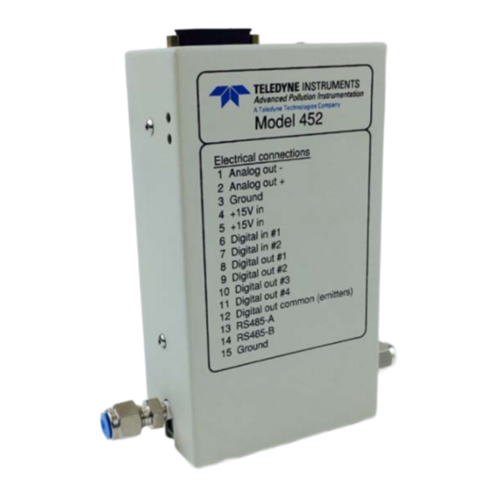
Teledyne API M452 Ozone Sensor Instruction Manual, 02852F DCN7659 4.3.1 Power Supply The M452 requires a +15 VDC power source capable of supplying 1.0 A. DC power can be connected through the male DB-15 connector or through the coaxial power jack. The coaxial power jack is configured so that the ground connection is on the outside (shield) and the +15V connection is on the center pin. -
Page 14: Status Outputs
PLC Figure 4-2: Digital Output Connections 4.3.5 RS232/485 Interface The M452 features a bi-directional digital serial interface that can be used for sensor control and data acquisition. Please contact Teledyne API for documentation on the use of the RS232/485 interface. -
Page 15: Gas Connections
Teledyne API M452 Ozone Sensor Instruction Manual, 02852F DCN7659 4.4 Gas Connections Gas connections to the M452 are made using ¼” compression tube fittings (M452) or ¼” VCR face seal fittings (M452A.) The ¼” compression fittings can be used with ¼” O.D. Stainless Steel or Teflon... -
Page 16: Maintenance
Teledyne API M452 Ozone Sensor Instruction Manual, 02852F DCN7659 5 Maintenance The only user-serviceable part in the Model 452 is the lamp, which can be adjusted or replaced. For all other service, contact TAPI Technical Support. WARNING High voltages exist inside the sensor. Use caution when sensor cover is removed. -
Page 17: Figure 5-1. Cover Assembly Screws
Teledyne API M452 Ozone Sensor Instruction Manual, 02852F DCN7659 Figure 5-1. Cover Assembly Screws Figure 5-2. UV Lamp Orientation... -
Page 18: Figure 5-3. Voltage Adjustment Locations
Teledyne API M452 Ozone Sensor Instruction Manual, 02852F DCN7659 Figure 5-3. Voltage Adjustment Locations... -
Page 19: Measuring And Adjusting Uv Lamp Reference And Measurement Voltages
Teledyne API M452 Ozone Sensor Instruction Manual, 02852F DCN7659 5.1.1 Measuring and Adjusting UV Lamp Reference and Measurement Voltages 1. Flush the analyzer with zero gas to exhaust any possible residual high concentration of O 2. Remove the analyzer from the equipment (if necessary) to access the cover screws and the internal components of the analyzer. -
Page 20: Replacing The Lamp
Teledyne API M452 Ozone Sensor Instruction Manual, 02852F DCN7659 must be replaced. If a positional adjustment lowers TP5 voltage to below -.8V, adjust the Reference and Measure voltages as follows. 2. Measure and record the Reference voltage. a. Measure the DC Voltage from GND J9 pin 1 to TP REF (Figure 5-3). - Page 21 Teledyne API M452 Ozone Sensor Instruction Manual, 02852F DCN7659 lamp retaining screws and rotate the UV lamp until this voltage is reached and then tighten the screws back down again. If this voltage can not be reached then contact API for further assistance.
-
Page 22: Sensor And System Troubleshooting
Teledyne API M452 Ozone Sensor Instruction Manual, 02852F DCN7659 6 Sensor and System Troubleshooting This chapter gives guidelines for diagnosing system and sensor malfunctions using the four digital Status Outputs provided by the M452. All troubleshooting should be done after the M452 has been turned on and allowed to warm up for at least 15 minutes. -
Page 23: Sensor O.k
Teledyne API M452 Ozone Sensor Instruction Manual, 02852F DCN7659 6.3 Sensor O.K. The normal state for the Sensor O.K. output in ON. During the warm-up period on start-up this output will stay off until the UV lamp reaches a minimum intensity. If this output remains off after the 15 minute warm-up period, or goes off during normal operation, then the M452 is in need of servicing. -
Page 24: Cell Dirty
Teledyne API M452 Ozone Sensor Instruction Manual, 02852F DCN7659 6.6 Cell Dirty The normal state for the Cell Dirty output is OFF. If this output turns on, then the ratio of the measure detector to the reference detector (at zero) is < 0.5. This value is calculated when the zero calibration is performed.
Need help?
Do you have a question about the 452 and is the answer not in the manual?
Questions and answers