Table of Contents
Advertisement
Quick Links
FEATURES
•
Full Frame Spectroscopic Sensor
•
2048 by 264 Pixel Format
15µm Square Pixels
•
Active image area 30.72 x 3.96 mm
•
•
Deep Depleted for higher red response
•
Advanced Inverted Mode Operation (AIMO)
INTRODUCTION
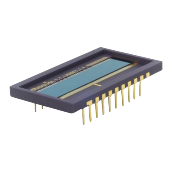
The CCD261-04 is a full frame spectroscopic format
sensor product from Teledyne e2v.
The CCD261-04 has 2048(H) x 264(V) elements.
Each element is 15 µm square. Standard three phase
clocking and buried channel charge transfer are
employed and Advanced Inverted Mode Operation
(AIMO) is included as standard. Teledyne e2v's AIMO
structure gives a 100 times reduction in dark current
with minimum reduction in full well capacity. Novel
Deep Depletion AIMO technology enhances IR
sensitivity while preserving high spatial resolution and
low dark current.
Designers are advised to consult Teledyne e2v should
they be considering using CCD sensors in abnormal
environments or if they require customised packaging
or performance features.
Whilst Teledyne e2v has taken care to ensure the accuracy of the information contained herein it accepts no responsibility for the consequences of any use thereof and
also reserves the right to change the specification of goods without notice. Teledyne e2v accepts no liability beyond that set out in its standard conditions of sale in
respect of infringement of third party patents arising from the use of tubes or other devices in accordance with information contained herein.
Teledyne UK Limited, Waterhouse Lane, Chelmsford, Essex CM1 2QU United Kingdom Teledyne UK Ltd. is a Teledyne Technologies company.
Telephone: +44 (0)1245 493493 Facsimile: +44 (0)1245 492492
Enquiries@Teledyne-e2v.com
Contact Teledyne e2v by e-mail:
© Teledyne UK Limited 2020
Template: DF764388A Ver 19
CCD261-04 Back Illuminated AIMO
TYPICAL PERFORMANCE
Pixel readout frequency
Output amplifier sensitivity
Peak signal
Spectral range
GENERAL DATA
Format
Active Image area
Active pixels
Pixel size
Number of output amplifiers 1
Package
Overall dimensions
Number of pins
Inter-pin spacing
Package type
www.teledyne-e2v.com
or visit
for global sales and operations centres.
Deep Depleted CCD Sensor
1 MHz
6.3 µV/e
-
75 ke
/pixel
-
250–1050 nm
30.72 x 3.96 mm
2048 (H) x 264 (V)
15µm square
35.5 x 20.0 mm
20
2.54 mm
Ceramic DIL
A1A-795878 Version 1, May 2020
131037
Advertisement
Table of Contents

Related Manuals for Teledyne Everywhereyoulook CCD261-04


Summary of Contents for Teledyne Everywhereyoulook CCD261-04
- Page 1 Whilst Teledyne e2v has taken care to ensure the accuracy of the information contained herein it accepts no responsibility for the consequences of any use thereof and also reserves the right to change the specification of goods without notice. Teledyne e2v accepts no liability beyond that set out in its standard conditions of sale in respect of infringement of third party patents arising from the use of tubes or other devices in accordance with information contained herein.
- Page 2 T = - 10 °C. For more information, refer to the technical note "Dark Signal and Clock-Induced Charge in L3Vision CCD Sensors” DSNU is defined as the 1σ variation of the dark signal. © Teledyne UK Limited 2020 Document subject to disclaimer on page 1 A1A-795787 Version 1, page 2...
-
Page 3: Typical Spectral Response
Pixels where charge is temporarily held. Traps are counted if they have a capacity greater Traps than 500 e at 263 K. − © Teledyne UK Limited 2020 Document subject to disclaimer on page 1 A1A-795787 Version 1, page 3... -
Page 4: Device Schematic
TYPICAL VARIATION OF DARK SIGNAL WITH TEMPERATURE DEVICE SCHEMATIC Not all connections are shown. © Teledyne UK Limited 2020 Document subject to disclaimer on page 1 A1A-795787 Version 1, page 4... -
Page 5: Electrical Interface
14) If all voltages are set to the ‘typical’ values, operation at or close to specification should be obtained. Some adjustment within the minimum – maximum range specified may be required to optimise performance. © Teledyne UK Limited 2020 Document subject to disclaimer on page 1... - Page 6 It is also important to ensure that excess currents do not flow in the OS pins. Such currents could arise from rapid charging of a signal coupling capacitor or from an incorrectly biased DC-coupled preamplifier. © Teledyne UK Limited 2020 Document subject to disclaimer on page 1...
- Page 7 FRAME READOUT TIMING DIAGRAM DETAIL OF LINE TRANSFER (Not to scale) © Teledyne UK Limited 2020 Document subject to disclaimer on page 1 A1A-795787 Version 1, page 7...
- Page 8 15) No maximum other than that necessary to achieve an acceptable dark signal at longer readout times and general compliance to the line transfer timing diagram. Scale to T 16) Determined by readout time requirement. 17) Scale to T © Teledyne UK Limited 2020 Document subject to disclaimer on page 1 A1A-795787 Version 1, page 8...
-
Page 9: Output Circuit
First stage load Node Signal charge NOTES 18) The amplifier has a DC restoration circuit, which is activated internally whenever IØ3 is pulsed high. © Teledyne UK Limited 2020 Document subject to disclaimer on page 1 A1A-795787 Version 1, page 9... - Page 10 PACKAGE (All dimensions are nominal and are in mm) © Teledyne UK Limited 2020 Document subject to disclaimer on page 1 A1A-795787 Version 1, page 10...
- Page 11 It is therefore important to use the specified bias levels and the switch-on and switch-off sequences. © Teledyne UK Limited 2020 Document subject to disclaimer on page 1...
-
Page 12: Ordering Information
• Working at a fully grounded workbench For further information on the performance of this • Operator wearing a grounded wrist strap and other options, please contact Teledyne e2v. • All receiving socket pins to be positively grounded • Unattended CCDs should not be left out of their conducting foam or socket.
Need help?
Do you have a question about the Everywhereyoulook CCD261-04 and is the answer not in the manual?
Questions and answers