Table of Contents
Advertisement
Quick Links
Advertisement
Table of Contents

Related Manuals for Texas Instruments Chipcon CC2430DB


Summary of Contents for Texas Instruments Chipcon CC2430DB
- Page 1 CC2430DB Demonstration Board User Manual SWRU125 Page 1...
-
Page 2: Table Of Contents
Table of content Introduction........................3 Definitions........................3 Kit content ........................3 Hardware........................3 Getting started.........................3 Hardware description CC2430DB..................4 Powering CC2430DB ....................4 USB Interface......................5 User interface......................5 EEPROM........................5 Accelerometer ......................5 Potentiometer......................5 Light sensor.........................6 I/O connectors......................6 Jumper settings......................7 5.9.1 P3 Jumpers ......................7 5.9.2 P5 Jumpers ......................8 5.10 Signal flow ......................9 Using CC2430DB for prototyping ..................10 Debugging using the USB interface ................10... -
Page 3: Introduction
1 Introduction This manual contains reference information for the CC2430 DB hardware. The following tools, which can be used with the kit, have their own user manual that can be downloaded from the TI website: ® SmartRF Studio Chipcon general packet sniffer IAR EW8051 C-compiler and C-Spy debugger (www.IAR.se) The CC2430DB demonstration board includes a number of functions and applications that allows quick testing of the RF interface and peripherals of the CC2430. -
Page 4: Hardware Description Cc2430Db
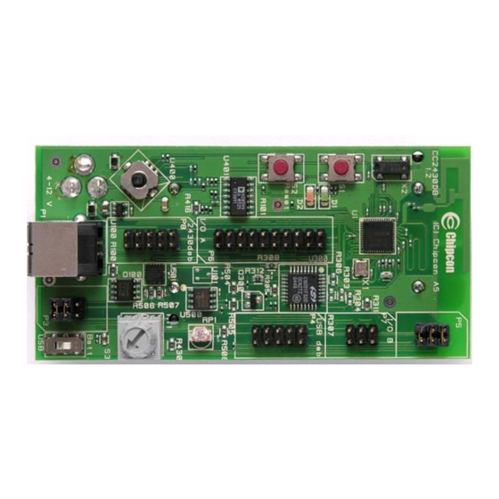
5 Hardware description CC2430DB Joystick I/O connector A CC2430 Reset CC2430 Button S1 debug CC2430 DC jack (Reverse) connector Antenna Battery clip (Reverse) Low current jumpers Low current Power switch S3 USB MCU jumpers debug Pot. connector I/O connector B Accelerometer Light sensor USB MCU... -
Page 5: Usb Interface
Figure 2: Power switch setting The Power Switch S3 must be set according to what power source is used. If DC jack or USB power is applied, the switch should be set to the USB position. If the board is powered from batteries, the switch should be set to the BATT position as shown in Figure 2. -
Page 6: Light Sensor
5.7 Light sensor A light dependent resistor (LDR) measures light level and gives an analog signal that is measured by the CC2430 A/D converter. The light sensor resistance ranges from 5KΩ (light) to 20MΩ (dark). 5.8 I/O connectors The I/O connectors bring out all the signals from CC2430. These connectors allow easy access to all CC2430 I/O pins. -
Page 7: Jumper Settings
5.9 Jumper settings P5, pin 1-2: Connects DD (Debug Data) P3, pin 5-6: Accelerometer self test P3, pin 3-4: SW controlled power P5, pin 3-4: Connects DC (Debug Clock) P5, pin 5-6: Connects RESET_N P3, pin 1-2: Replace with ampere meter to measure current consumption of CC2430 Figure 3: CC2430DB Jumper settings... -
Page 8: P5 Jumpers
The jumper between pin 3-4 can be removed when performing current measurement to reduce leakage current of the peripheral devices connected to the CC2430. The jumper must be mounted for normal operation The jumper between pin 5-6 can be mounted to perform accelerometer self test function. By mounting this jumper, a voltage is applied to the accelerometer outputs. -
Page 9: Signal Flow
5.10 Signal flow The signal lines from the I/O connectors and the CC2430 run via 0Ω resistors to the various peripherals on the CC2430DB. The peripherals can be disconnected from the CC2430 signal pins by removing the 0Ω resistors. Please refer to Table 6 for a list of what resistors correspond to which signals. -
Page 10: Using Cc2430Db For Prototyping
6 Using CC2430DB for prototyping The CC2430DB can be used for prototyping by programming the CC2430 with custom applications. All I/O ports on the CC2430 are available on pin row header at the edge of the board, and the USB interface can be used as In Circuit Emulator (ICE) interface allowing real time in circuit emulation of the CC2430. -
Page 11: Low Power Operation
6.3 Low power operation CC2430DB is designed for low power operation when running from batteries. Only the CC2430 is powered in this mode, the USB MCU is not powered. The voltage to the peripheral functions connected to the CC2430 is controlled by an I/O pin P1.2 (VDD_SW_CTRL) on the CC2430. - Page 12 Active mode (mA) Power down mode (µA) Device Typical 32KHz Sleep CC2430 1µA 0.3µA EEPROM Accelerometer 0,49 Potentiometer 0,33 Light sensor 0,001 0.015 LEDs Total 54mA 1µA Table 4: Current consumption summary To accurately measure the current consumption of the chip the jumpers listed in Table 5 should be removed.
-
Page 13: Using The Uart Interface On The Cc2430Db
P1_2/VDD_SW Voltage control for I/O P1_2 _CTRL modules HIGH Free I/O for controlling P1_3 P1_3/GPIO external signal P1_4/CSn/SS/ P1_4 R305 P1_5/SCLK/RT P1.5 R308 P1_6/SI/MOSI/ P1_6 R306 UART_TD P1_7/SO/MISO P1_7 R307 /UART_RD Joystick push interrupt P2_0 P2_0/Joy_push active high Jumper P2_1 P2_1/DD Debug Data Jumper... -
Page 14: Programming Cc2430 With A Hex File
7 Programming CC2430 with a HEX file The CC2430 can be programmed from the USB interface using the Chipcon programming software. Figure 9 shows the flash programming interface. For additional information regarding Chipcon Flash Programmer please refer to Chipcon Flash Programmer User Manual. -
Page 15: Bill Of Materials (Bom)
9 Bill of Materials (BOM) Pcs/ Ref. Part name unit Description Manufacturer Part number Mounting clip for one B1-2 1XAA_1_5V AA battery cell Keystone U500 24AA32A/SN 4 KB I2C EEPROM Microchip 24AA32A/SN Analog U401 AD8544 Rail-to-rail quad opamp Devices AD8544AR 18 g peak X,Y Analog U501... - Page 16 2x3 pinrow, 2.54mm P3;P5;P7 PINROW_2X3 0-0826632-3 pitch, through-hole 2x5 pinrow, 2.54mm P4;P8 PINROW_2X5 pitch, through-hole 0-0826632-5 Momentary push- S1-2 PUSH_BUTTON button, SMD Alps SKHUAF 10k trimming pot with R_0-10K_TRIM 72PTR10K knob Technologies R303-304; Resistor, general, 0603; R311-312 R_0603 Do not mount R100;R305;R306- 307;...
-
Page 17: Document History
10 Document History Revision Date Description/Changes 2007-04-16 Initial release SWRU125 Page 17... - Page 18 TI as compliant with ISO/TS 16949 requirements. Buyers acknowledge and agree that, if they use any non-designated products in automotive applications, TI will not be responsible for any failure to meet such requirements. Following are URLs where you can obtain information on other Texas Instruments products and application solutions: Products...
- Page 19 Mouser Electronics Authorized Distributor Click to View Pricing, Inventory, Delivery & Lifecycle Information: Texas Instruments CC2430DB...
Need help?
Do you have a question about the Chipcon CC2430DB and is the answer not in the manual?
Questions and answers