Table of Contents
Advertisement
Quick Links
USER MANUAL
NI 9757
NI Powertrain Controls O2 Sensor Module Kit - Rev E
Contents
Introduction .............................................................................................................................. 2
Pinout........................................................................................................................................ 2
Hardware .................................................................................................................................. 2
Powering the Module................................................................................................................ 3
Platform Compatibility ............................................................................................................. 3
Bosch USA LSU 4.x Wide-Band Oxygen Sensor Controllers................................................. 4
Narrow-Band Oxygen Sensor Inputs........................................................................................ 7
Physical Specifications and Characteristics ............................................................................. 8
Electrical Specifications and Characteristics............................................................................ 8
Compliance and Certifications ................................................................................................. 9
Advertisement
Table of Contents

Related Manuals for National Instruments NI 9757


Summary of Contents for National Instruments NI 9757
-
Page 1: Table Of Contents
USER MANUAL NI 9757 NI Powertrain Controls O2 Sensor Module Kit - Rev E Contents Introduction ..........................2 Pinout............................2 Hardware ..........................2 Powering the Module........................ 3 Platform Compatibility ......................3 Bosch USA LSU 4.x Wide-Band Oxygen Sensor Controllers..........4 Narrow-Band Oxygen Sensor Inputs.................. -
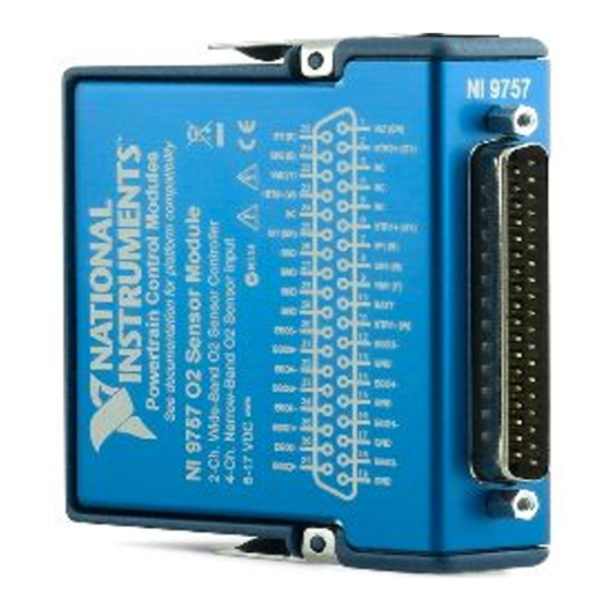
Page 2: Introduction
Figure 1. NI 9757 Pin Assignments Hardware The NI 9757 Sensor Module Kit (part number 782079-01) includes controllers for Bosch USA LSU 4.2 or LSU 4.9 wide-band oxygen sensors, and inputs for zirconium-dioxide-element, narrow-band oxygen sensors. Wide-band oxygen sensors may also be referred to as Universal... -
Page 3: Powering The Module
Exhaust Gas Oxygen (UEGO) sensors. Narrow band sensors may also be referred to as Exhaust Gas Oxygen (EGO) sensors. NI recommends using the NI 9923 Connector Kit for connecting to the NI 9757. The NI 9923 provides proper strain relief for NI 9757 connections. Visit and enter Info Code ni.com/info... -
Page 4: Bosch Usa Lsu 4.X Wide-Band Oxygen Sensor Controllers
Bosch USA LSU 4.x Wide-Band Oxygen Sensor Controllers The NI 9757 Sensor Module Kit (part number 782079-01) includes two Bosch USA LSU 4.2 and LSU 4.9 Universal Exhaust Gas Oxygen (UEGO) sensor controllers. The NI 9757 controls the pump current, referred to as Ip, to the sensor element to maintain a fixed voltage reference across the element. - Page 5 By default, the NI 9757 is configured to use the LSU 4.9 sensor. Figure 2 illustrates the top of the circuit card assembly inside the module housing. The switch position for the associated sensor type is labeled next to the switch.
- Page 6 LSU 4.2 and LSU 4.9 sensor connectors, respectively, to the intermediate cable and to the NI 9757. The NI 9757 module housing label provides wire color information next to the DB-37 pin names according to the standard Bosch USA LSU 4.x sensor wire coloring, not according to the intermediate wiring.
-
Page 7: Narrow-Band Oxygen Sensor Inputs
Connect the black wire to the EGO+ pin of the NI 9757 DB-37 connector. Connect the gray wire to one of the EGO- pins for the associated channel of the NI 9757 DB-37 connector. The two white wires connect to a resistive heater element inside the EGO sensor. -
Page 8: Physical Specifications And Characteristics
Analog Measurement Hardware Filter ..1st order RC lowpass, 16 Hz cutoff Pump Current (Ip) Measurement Range ...–2.0 to 2.4 mA Pump Current (Ip) Measurement Resolution ..........1 µA Pump Current (Ip) Measurement Accuracy ...........± 0.1 % Lambda Measurement Range ....0.65 to 15.99 8 | ni.com | NI 9757 User Manual... -
Page 9: Compliance And Certifications
Measurement Accuracy ......± 0.1 % Input Over-Voltage Protection ....–15 to 44 V Safety Guidelines Do not operate the NI 9757 n a manner not specified in these operating Caution instructions. Product misuse can result in a hazard. You can compromise the safety protection built into the product if the product is damaged in any way. - Page 10 At the end of the product life cycle, all products must be sent to a WEEE recycling center. For more information about WEEE recycling centers, National Instruments WEEE initiatives, and compliance with WEEE Directive 2002/96/EC on Waste and Electronic Equipment, visit ni.com/environment/...
- Page 11 NI product. Refer to the Export Compliance Information at ni.com/legal/ export-compliance for the National Instruments global trade compliance policy and how to obtain relevant HTS codes, ECCNs, and other import/export data. NI MAKES NO EXPRESS OR IMPLIED WARRANTIES AS TO THE ACCURACY OF THE INFORMATION CONTAINED HEREIN AND SHALL NOT BE LIABLE FOR ANY ERRORS.
Need help?
Do you have a question about the NI 9757 and is the answer not in the manual?
Questions and answers