National Instruments NI-9425 Operating Instructions And Specifications
32-channel, 24 v sinking digital input module
Hide thumbs
Also See for NI-9425:
- Operating instructions manual (23 pages) ,
- Getting started manual (21 pages) ,
- Getting started (11 pages)

Related Manuals for National Instruments NI-9425


Summary of Contents for National Instruments NI-9425
- Page 1 OPERATING INSTRUCTIONS AND SPECIFICATIONS NI 9425E 32-Channel, 24 V Sinking Digital Input Module...
- Page 2 C Series documentation. cseriesdoc National Instruments makes no electromagnetic Caution compatibility (EMC) or CE marking compliance claims for the NI 9425E. The end-product supplier is responsible for conformity to any and all compliance requirements.
- Page 3 NI 9425E Dimensions The following figure shows the dimensions of the NI 9425E. Figure 1. NI 9425E Dimensions in Millimeters (Inches) 73.4 (2.89) 0.0 (0.00) NI 9425E Operating Instructions and Specifications | © National Instruments | 3...
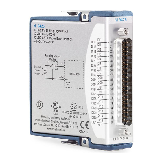
- Page 4 Connecting the NI 9425E The NI 9425E has a 37-pin DSUB connector that provides connections for 32 simultaneously-sampled digital input channels. Figure 2. NI 9425E Pin Assignments DI16 DI17 DI18 DI19 DI20 DI21 DI22 DI23 DI24 DI25 DI10 DI26 DI11 DI27 DI12 DI28...
- Page 5 You can connect 2-, 3-, and 4-wire sourcing-output devices to the NI 9425E. A sourcing-output device drives current or applies voltage to the DI pin. An example of a sourcing-output device is an open collector PNP. NI 9425E Operating Instructions and Specifications | © National Instruments | 5...
- Page 6 Connect the sourcing-output device to the DI pin on the NI 9425E. Connect the common of the external device to the COM pin. Refer to Figure 3 for an illustration of connecting a device to the NI 9425E. Figure 3. Connecting a Device to the NI 9425E (Three-Wire Device Shown) Sourcing-Output Device...
-
Page 7: Sleep Mode
Specifications in normal mode. Refer to the section for more information about power consumption and thermal dissipation. NI 9425E Operating Instructions and Specifications | © National Instruments | 7... -
Page 8: Specifications
Specifications The following specifications are typical for the range -40 to 70 °C unless otherwise noted. All voltages are relative to COM unless otherwise noted. Input Characteristics Number of channels......32 digital input channels Input type .......... Sinking Digital logic levels OFF state Input voltage ...... - Page 9 Hold time is the amount of time input signals must be stable after initiating a read from the module. Setup time is the amount of time input signals must be stable before reading from the module. NI 9425E Operating Instructions and Specifications | © National Instruments | 9...
-
Page 10: Power Requirements
Contact NI for Bellcore MTBF specifications Note at other temperatures or for MIL-HDBK-217F specifications. Power Requirements Power consumption from chassis Active mode ....... 410 mW max Sleep mode ......... 0.5 mW max Thermal dissipation (at 70 °C) Active mode ....... 1.45 W max Sleep mode ......... - Page 11 Such voltage measurements include signal levels, special equipment, limited-energy parts of equipment, circuits powered by regulated low-voltage sources, and electronics. NI 9425E Operating Instructions and Specifications | © National Instruments | 11...
-
Page 12: Safety Standards
Do not connect the NI 9425E to signals or use Caution for measurements within Measurement Categories II, III, or IV. Measurement Categories CAT I and CAT O Caution (Other) are equivalent. These test and measurement circuits are not intended for direct connection to the MAINS building installations of Measurement Categories CAT II, CAT III, or CAT IV. -
Page 13: Online Product Certification
Sinusoidal (IEC 60068-2-6) ..5 g, 10 to 500 Hz Operating shock (IEC 60068-2-27)......30 g, 11 ms half sine, 50 g, 3 ms half sine, 18 shocks at 6 orientations NI 9425E Operating Instructions and Specifications | © National Instruments | 13... - Page 14 Environmental Refer to the manual for the chassis you are using for more information about meeting these specifications. Operating temperature (IEC 60068-2-1, IEC 60068-2-2) ..-40 to 85°C Measure the local ambient temperature by placing Note thermocouples on both sides of the PCB, 0.2 in. (5 mm) from the board surface.
-
Page 15: Environmental Management
Our Environmental Impact web page at ni.com/environment This page contains the environmental regulations and directives with which NI complies, as well as other environmental information not included in this document. NI 9425E Operating Instructions and Specifications | © National Instruments | 15... -
Page 16: Waste Electrical And Electronic Equipment (Weee)
At the end of the product life cycle, all EU Customers products must be sent to a WEEE recycling center. For more information about WEEE recycling centers, National Instruments WEEE initiatives, and compliance with WEEE Directive 2002/96/EC on Waste and Electronic Equipment, visit ni.com/environment/... -
Page 17: Worldwide Support And Services
You can obtain the DoC for your product by visiting . If your product supports calibration, ni.com/certification you can obtain the calibration certificate for your product ni.com/calibration NI 9425E Operating Instructions and Specifications | © National Instruments | 17... - Page 18 For patents covering National Instruments products/technology, refer to the appropriate location: Help»Patents in your software, the patents.txt file on your media, or the National Instruments Patent Notice at ni.com/patents . You can find information about end-user license agreements (EULAs) and third-party legal notices in the readme file for your NI product.
Need help?
Do you have a question about the NI-9425 and is the answer not in the manual?
Questions and answers