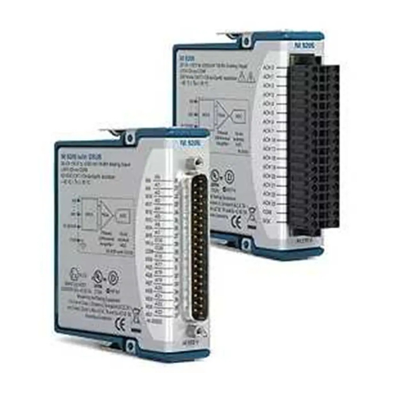
National Instruments NI-9214 Manual
Hide thumbs
Also See for NI-9214:
- Operating instructions and specifications (45 pages) ,
- Getting started manual (22 pages) ,
- Getting started manual (22 pages)
Table of Contents
Advertisement
Quick Links
Advertisement
Table of Contents

Subscribe to Our Youtube Channel
Summary of Contents for National Instruments NI-9214
- Page 1 NI-9214 2023-04-25...
-
Page 2: Table Of Contents
NI-9214 Contents Overview..............3 Safety Guidelines. -
Page 3: Overview
Refer to the documentation for each component in the system to determine the safety and EMC ratings for the entire system. © 2010–2016 National Instruments Corporation. All rights reserved. Refer to the <National Instruments>\_Legal Information directory for information about NI copyright, patents, trademarks, warranties, product warnings, and export compliance. -
Page 4: Safety Guidelines For Hazardous Voltages
NI-9214 Hazardous Voltage This icon denotes a warning advising you to take precautions to avoid electrical shock. Safety Guidelines for Hazardous Voltages If hazardous voltages are connected to the device, take the following precautions. A hazardous voltage is a voltage greater than 42.4 Vpk voltage or 60 VDC to earth ground. -
Page 5: Safety Guidelines For Hazardous Locations
For Division 2 and Zone 2 applications, install the system in an enclosure rated to at least IP54 as defined by IEC/EN 60079-15. Caution For Division 2 and Zone 2 applications, connected signals must be within the following limits. © National Instruments... -
Page 6: Electromagnetic Compatibility Guidelines
NI-9214 Capacitance 0.2 µF maximum Special Conditions for Hazardous Locations Use in Europe and Internationally The NI 9214 has been evaluated as Ex nA IIC T4 Gc equipment under DEMKO Certificate No. 07 ATEX 0626664X and is IECEx UL 14.0089X certified. Each NI 9214 is marked II 3G and is suitable for use in Zone 2 hazardous locations, in ambient temperatures of -40 °C ≤... -
Page 7: Special Conditions For Marine Applications
Furthermore, any changes or modifications to the product not expressly approved by National Instruments could void your authority to operate it under your local regulatory rules. Special Conditions for Marine Applications Some products are Lloyd’s Register (LR) Type Approved for marine (shipboard) -
Page 8: Tb-9214 Pinout
NI-9214 TB-9214 Pinout TC5+ TC0+ TC5- TC0- TC6+ TC1+ TC6- TC1- TC10+ TC7+ TC2+ TC13+ TC10- TC7- TC2- TC13- TC11+ TC8+ TC3+ TC14+ TC11- TC8- TC3- TC14- TC12+ TC9+ TC4+ TC15+ TC12- TC9- TC4- TC15- Table 1. Signal Descriptions Signal... -
Page 9: Minimizing Thermal Gradients
What to Use TB-9214 ■ 0.05 mm to 0.5 mm (30 AWG to 20 AWG) wire with 5.1 mm (0.2 in.) of the ■ inner insulation stripped and 51 mm (2.0 in.) of the outer insulation stripped © National Instruments... -
Page 10: Installing The Tb-9214
NI-9214 Zip tie ■ Screwdriver ■ What to Do 1. Loosen the captive screws on the TB-9214 and remove the top cover and foam pad. 2. Insert the stripped end of the wire fully into the appropriate terminal and tighten the screw for the terminal. Make sure no exposed wire extends past the screw terminal. -
Page 11: Where To Go Next
1 866 ASK MYNI (275 6964). For telephone support outside the United States, visit the Worldwide Offices section of ni.com/niglobal to access the branch office websites, which provide up-to-date contact information, support phone numbers, email addresses, and current events. © National Instruments © 2023 National Instruments Corporation.


Need help?
Do you have a question about the NI-9214 and is the answer not in the manual?
Questions and answers