National Instruments NI 9474 Getting Started Manual
8 do, 5 v to 30 v, sourcing, 1 ?s
Hide thumbs
Also See for NI 9474:
- Operating instructions manual (32 pages) ,
- Operating instructions manual (29 pages) ,
- Getting started (11 pages)
Table of Contents
Advertisement
Quick Links
Advertisement
Table of Contents

Related Manuals for National Instruments NI 9474


Summary of Contents for National Instruments NI 9474
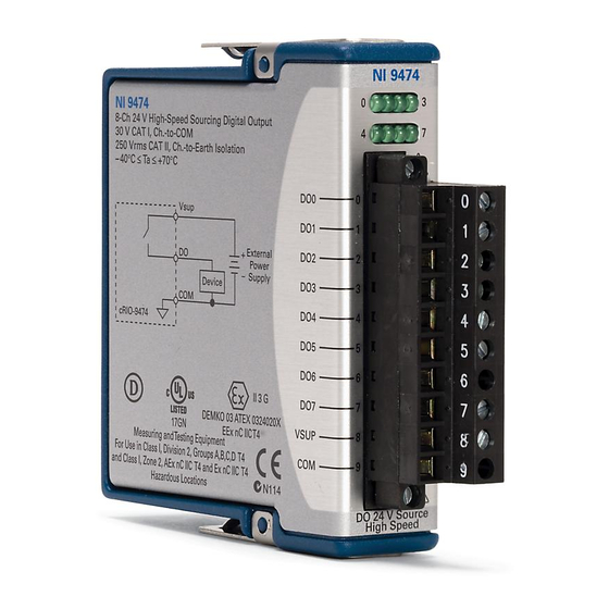
- Page 1 GETTING STARTED GUIDE NI 9474 8 DO, 5 V to 30 V, Sourcing, 1 μs...
-
Page 2: Safety Guidelines
This document explains how to connect to the NI 9474. In this document, the NI 9474 with screw terminal and the NI 9474 with spring terminal are referred to inclusively as the NI 9474. Before you begin, complete the software and... -
Page 3: Safety Voltages
Category II Withstand 2,300 Vrms, verified by a 5 s dielectric withstand test Measurement Category II is for measurements performed on circuits directly connected to the electrical distribution system. NI 9474 Getting Started Guide | © National Instruments | 3... -
Page 4: Safety Guidelines For Hazardous Voltages
This category refers to local-level electrical distribution, such as that provided by a standard wall outlet, for example, 115 V for U.S. or 230 V for Europe. Do not connect the NI 9474 to signals or use Caution for measurements within Measurement Categories III or IV. -
Page 5: Safety Guidelines For Hazardous Locations
Safety Guidelines for Hazardous Locations The NI 9474 is suitable for use in Class I, Division 2, Groups A, B, C, D, T4 hazardous locations; Class I, Zone 2, AEx nA IIC T4 and Ex nA IIC T4 hazardous locations;... - Page 6 Zone 2 hazardous locations, in ambient temperatures of -40 °C ≤ Ta ≤ 70 °C. If you are using the NI 9474 in Gas Group IIC hazardous locations, you must use the device in an NI chassis that has been evaluated as Ex nC IIC T4, Ex IIC T4, Ex nA IIC T4, or Ex nL IIC T4 equipment.
-
Page 7: Electromagnetic Compatibility Guidelines
This product is intended for use in industrial locations. However, harmful interference may occur in some installations, when the NI 9474 Getting Started Guide | © National Instruments | 7... -
Page 8: Special Conditions For Marine Applications
In order to meet the EMC requirements for Caution marine applications, install the product in a shielded enclosure with shielded and/or filtered power and input/output ports. In addition, take precautions when designing, selecting, and installing measurement probes 8 | ni.com | NI 9474 Getting Started Guide... -
Page 9: Preparing The Environment
EMC performance is attained. Preparing the Environment Ensure that the environment in which you are using the NI 9474 meets the following specifications. Operating temperature -40 °C to 70 °C (IEC 60068-2-1, IEC 60068-2-2) - Page 10 NI 9474 Pinout Vsup Vsup 10 | ni.com | NI 9474 Getting Started Guide...
- Page 11 Table 2. LED Indicators LED Pattern Indication Solid The channel has been programmed to be in the ON state. The channel has been programmed to be in the OFF state. NI 9474 Getting Started Guide | © National Instruments | 11...
-
Page 12: Connecting Digital Devices
Connecting Digital Devices You can connect a variety of industrial devices, such as solenoids, motors, actuators, relays, and lamps to the NI 9474. You must connect an external power supply to the NI 9474. The power supply provides the current for the output channels. -
Page 13: Increasing Current Drive
CSeriesDOPulseGen Increasing Current Drive Each channel of the NI 9474 has a continuous output current of 1.0 A. If you want to increase the output current to a device, you can connect any number of channels together in parallel. -
Page 14: High-Vibration Application Connections
Figure 2. Increasing the Current to a Device Connected to the NI 9474 External Power Supply NI 9474 High-Vibration Application Connections If your application is subject to high vibration, NI recommends that you follow these guidelines to protect connections to the NI 9474: •... - Page 15 Because the NI 9474 includes internal flyback Note diodes, you do not need to add external diodes when connecting to switching devices that store energy. NI 9474 Getting Started Guide | © National Instruments | 15...
-
Page 16: Power Supplies And Overcurrent Conditions
NI 9474. If the power supply you are using with the NI 9474 cannot supply more than 14 A, the module may be damaged if a short circuit condition occurs. -
Page 17: Resetting Channels After An Overcurrent Condition
Alternatively, you can disconnect the external power supply from the chassis. However, doing so disconnects power from all the module channels. Normal operation can resume after you correct the overcurrent condition and reset the channel. NI 9474 Getting Started Guide | © National Instruments | 17... -
Page 18: Where To Go Next
NI 9474 Datasheet NI 9474 Datasheet NI-RIO Help NI-DAQmx Help LabVIEW FPGA Help LabVIEW Help RELATED INFORMATION C Series Documentation Services ni.com/services & Resources ni.com/info cseriesdoc Located at ni.com/manuals Installs with the software 18 | ni.com | NI 9474 Getting Started Guide... -
Page 19: Worldwide Support And Services
You can obtain the DoC for your product by visiting ni.com/certification. If your product supports calibration, you can obtain the calibration certificate for your product at ni.com/calibration. NI 9474 Getting Started Guide | © National Instruments | 19... - Page 20 U.S. Government Customers: The data contained in this manual was developed at private expense and is subject to the applicable limited rights and restricted data rights as set forth in FAR 52.227-14, DFAR 252.227-7014, and DFAR 252.227-7015. © 2003—2016 National Instruments. All rights reserved. 373974D-01 Mar16...
Need help?
Do you have a question about the NI 9474 and is the answer not in the manual?
Questions and answers