
Related Manuals for Anritsu AM-9000 Series


Summary of Contents for Anritsu AM-9000 Series
- Page 1 Thermologger AM-9000 Series User's Manual AE-100283 2nd edition Sep. 2020 Anritsu Meter Co., Ltd.
- Page 3 For safe use Please observe the following cautions of this product to ensure your safety, to prevent damage of this product, and to maintain accurate measurement results. Cautions ● Do not use this product for any purpose other than for temperature measurements. ●...
- Page 4 ■ Although this manual was prepared with the utmost care, if it has an omission or unclear point, please contact Anritsu Meter or our nearest distributor. ■ Anritsu Meter will not be liable for any consequences arising from the use of this product.
-
Page 6: Table Of Contents
Table of Contents Overview ........................... 1 Overview ........................1 Unpacking and Repacking ....................1 Unpacking ........................1 Repacking........................2 Preparing for Operation ....................3 Names of the Components ..................3 Key Names and Functions ..................5 Power Supply ....................... 6 3.3.1 Installing Dry-cell Batteries ................. - Page 7 Error Messages and Corrective Measures to Take ............23 Overrange and Sensor Burnout ................23 Memory Shortage ...................... 23 Dedicated Software AMS-950 ..................24 USB Connection ......................24 How to Take Out Data from the Measuring Instrument (AMS-950) ....25 Maintenance ........................
-
Page 9: Overview
Open the container of this product, and then check for the following included items. Although this product is packed with the utmost care, it may not include all the items or may contain a faulty item. In that case, please contact your distributor or Anritsu Meter. Thermologger main unit …………………... -
Page 10: Repacking
2.2 Repacking When transporting the AM-9000 Series Thermologger (e.g., by car), repack it in its original shipping container. If you do not have the original shipping container, sufficiently pack the instrument with shock absorbing material (e.g., polystyrene foam). The packaging material must be dry and must not produce dust or water; otherwise the instrument may become damaged. -
Page 11: Preparing For Operation
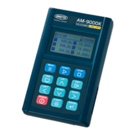
Preparing for Operation 3.1 Names of the Components Appearance of the 6-channel model: ① ② ④ ③ ⑤ ⑥ ① Sensor inputs ② Display ③ Keypad ④ Communication connector ⑤ DC jack ⑥ Battery compartment - 3 -... - Page 12 Appearance of the 12-channel model: ① ② ④ ③ ⑤ ⑥ ① Sensor inputs ② Display ③ Keypad ④ Communication connector ⑤ DC jack ⑥ Battery compartment - 4 -...
-
Page 13: Key Names And Functions
3.2 Key Names and Functions Key name Function Displays the main menu screen. Starts the measurement from the command waiting screen. Terminates the measurement. Changes the display mode during measurement or reproduction. Redisplays the command waiting screen during menu setup. Turns on or turns off the main power. -
Page 14: Power Supply
3.3 Power Supply Installing Dry-cell Batteries 3.3.1 1) Open the cover of the battery compartment, and insert the batteries with the correct polarity. 2) Close the cover. * The springs are strong enough to hold the batteries tight, so as to prevent instantaneous power failure. -
Page 15: Inserting Input Plugs
Inserting Input Plugs 3.3.3 1) Check the polarity (+/-) of the input plugs. (For the polarity, see the figure below.) 2) Check the polarity (+/-) of the inputs of the main unit. Then connect the plugs as shown in the figure on the right. (The positive polarity is closest to side of the display.) [Note] The input plugs must be optionally-available dedicated plugs (ANP series: dedicated... -
Page 16: Power-Up And Initial Screen
Display contents: 1st line: Product name 2nd line: Version number 3rd line: Company name <Initial screen of AM-9000 Series> After about three seconds, the display will change to the command waiting screen. Display contents: 1st line: Date & time 2nd line: Available memory/interval/machine number 3rd line: Channel settings <Command waiting screen of AM-9000>... -
Page 17: Descriptions Of Displayed Symbols
4.2 Descriptions of Displayed Symbols Some units of measurement shown on the display are simplified. Their meanings are described below. Displayed symbol Description Represents minutes and 00m01s seconds. C Represents Celsius (°C). Represents Celsius (°C). Represents voltage (V). Power Supply 5.1 Turning the Power Off Turning the Power Off by Key Operation Battery pictogram... -
Page 18: Starting Measurement And Configuring Settings
Starting Measurement and Configuring Settings You can perform four operations on the command waiting screen. START key: Starts measurement at the displayed interval. (See section 6.1.1.) MENU key: Allows you to configure settings such as the interval and calendar. (See section 6.2.) POWER key: Turns the power off. -
Page 19: Normal Measurement
Normal Measurement 6.1.1 Pressing the S T A R T key on the command waiting screen starts measurement. Measurement data is recorded in memory according to the specified channel information and interval. Available intervals vary depending on the model <Command waiting screen> - AM-9000 0.1 sec to 99 min 59 sec Current time... - Page 20 Long-interval measurement is carried out in sleep mode. During the measurement, operation and display are as usual, but communication from outside is not accepted. For sleep mode, see (5) in section 1.2, and for communication, see the user's manual of the dedicated personal computer software (AMS-950).
-
Page 21: Scheduled Measurement
Scheduled Measurement 6.1.2 Use the "RESERVE" function to set the start date & time and the end date & time of the measurement (year/month/day, hour, minute). Normal measurement is carried out at the start date & time, and the measurement is terminated at the end date & time. (See section 6.2.2.5.) If a measurement is scheduled and starts by using the START... -
Page 22: Real-Time Measurement
Real-time Measurement 6.1.4 Connect a personal computer and this instrument with supplied communication cable. Next, real-time measurement function of the dedicated personal computer software (AMS-950) on the command waiting screen to set the interval, and then start the measurement. <Command waiting screen> In real-time measurement, data is not recorded in the internal memory of this instrument. -
Page 23: Check (Check Measurement)
CHECK (Check Measurement) 6.2.1 No indication of available memory This function carries out a check measurement in which the measurement data is not recorded in memory. On the main menu screen, place the cursor at "CHECK" and then press the ENTER key to confirm the selection. -
Page 24: Channel (Channel Setup)
Cursor Cursor <Main menu screen> <Measurement condition setup screen> 6.2.2.1 CHANNEL (Channel Setup) This function allows you to set the measurement mode for each channel. On the measurement condition setup screen, place the cursor at "CHANNEL" and then press the ENTER key to confirm the selection. The channel setup (CHANNEL SET) screen will appear. -
Page 25: Resol (Resolution Setup)
6.2.2.2 RESOL (Resolution Setup) Highlighted This function allows you to set the measurement resolution. On the measurement condition setup screen, place the cursor at "RESOL", and then press the ENTER key to confirm the selection. The measurement resolution setup (RESOLUTION SET) screen will appear. <Resolution setup screen>... -
Page 26: Clock (Date & Time Setup)
* If the interval is set to 10 sec or longer, the system enters sleep mode when not performing measurements, allowing a reduction in power consumption. * The 50/60Hz filter is enabled if the interval is set to 0.7 sec or longer. * If there is an effect of noise, then set the interval to 1 sec or longer and consider other measures such as using a non-ground sensor. - Page 27 Timer pictogram ② Start of scheduled measurement: When the measurement schedule setting is set to "ON", the timer pictogram is displayed on the top right of the command waiting screen. Afterwards, at the start time, normal measurement starts. For normal measurement, see section 6.1.1. <Command waiting screen with scheduled measurement>...
-
Page 28: Manual (Manual Setup)
6.2.2.6 MANUAL (Manual Setup) This function allows you to enable or disable Cursor manual measurement. On the measurement condition setup screen, place the cursor at "MANUAL" and then press the ENTER key to confirm the selection. The manual setup (MANUAL SET) screen will appear. -
Page 29: Clear (Data Erase)
Key operations on the reproduction data display screen are as follows: Sample number Block number key: Shows the next one sample of data. key: Shows the previous one sample of data. key: Skips forward four samples of data. key: Skips back four samples of data. ESC... -
Page 30: Disp Function (Display Change)
DISP Function (Display Change) 6.2.5 When the measurement screen is displayed, pressing the DISP key changes display mode. For details, see the description of each measurement function. LIGHT Function (Backlight) 6.2.6 Pressing the LIGHT key turns the backlight on. If the screen is too dim, use this function. Also, when the backlight is turned on, pressing the LIGHT... -
Page 31: Error Messages And Corrective Measures To Take
Error Messages and Corrective Measures to Take 7.1 Overrange and Sensor Burnout Burnout Overrange If an overrange or sensor burnout occurs, indication indication "OVER" or "B-OUT" is displayed, respectively. If "OVER" is displayed, check whether the measured value is within the applicable range. If "B-OUT"... -
Page 32: Dedicated Software Ams-950
Dedicated Software AMS-950 The use of the dedicated personal computer software allows the Thermologger AM-9000 Series to communicate with a personal computer. Install AMS-950 (optionally available) according to the user's manual of the software. This software requires the following operating environment: Supported OS: Microsoft Windows 8.1 Microsoft Windows 10 A personal computer that has the specs required for the above OSs to operate... -
Page 33: How To Take Out Data From The Measuring Instrument (Ams-950)
8.2 How to Take Out Data from the Measuring Instrument (AMS-950) Upload the data stored in the measuring instrument onto a personal computer to create a file. 1) Make sure that the measuring instrument and the personal computer are connected, and turn on the measuring instrument. - Page 34 4) Select [Input data] from the [Communication(C)] menu. A dialog box will appear, asking " Start data input? " Selecting "Yes" starts the data input. 5) During communication, the transfer progress bar is displayed as shown below, allowing you to check the status of data transfer. If you press [Interruption], the communication is interrupted, and a file will not be created.
- Page 35 6) Upon completion of the data input, a newly created data file is displayed. [Note] About file names: A file is named Am-****.an4. "****" denotes sequential numbers from 0001 to 9999, which are assigned to each directory. Also, even if you delete a file, the numbers of other files remain unchanged. For example, if files numbered up to 9999 are stored on the hard disk and the files numbered 0001 to 9998 are deleted, then the file numbered 9999 is left alone.
-
Page 36: Maintenance
Maintenance 9.1 Storage When storing the Thermologger, avoid the following conditions: ◼ Exposure to direct sunlight ◼ Strong vibration ◼ High humidity (85% R.H. or higher) ◼ High temperatures (50°C or higher) ◼ Environment containing dust, waste, corrosive gas, or saline matter ◼... -
Page 37: Specifications
11 Specifications Fixed thermocouple type models: Model AM-9000 AM-9100 6 inputs: ANP connector 12 inputs: ANP connector Number of inputs (Input with the same type of (Input with the same type of metal as that of thermocouple) metal as that of thermocouple) Temperature: Select one from types E, K, J, T, or R Input type at the time of ordering *1... - Page 38 Multi-input models: Model AM-9200 AM-9300 6 inputs: ANP connector 12 inputs: ANP connector Number of inputs (copper/copper) (copper/copper) Temperature: Multi-input (E, K, J, T, R) Input type Voltage: V Temperature See table 1. Measurement range Voltage ±20.000V Temperature See table 2. Measurement accuracy Voltage...
- Page 39 Table 1: Measurement range Thermocouple Measurement range type Type E -200 to 800°C Type K -200 to 1370°C Type J -200 to 1100°C Type T -200 to 400°C Type R 0 to 1760°C Table 2: Measurement accuracy (excluding reference contact compensation accuracy, at 25°C ± 10°C) Thermocouple Accuracy AM-9000/AM-9100 AM-9200/AM-9300...
-
Page 40: Appendix
12 Appendix 12.1 Maximum Continuous Operating Time (25°C standard value during operation with AA alkaline batteries) Measurement interval Allowable operating time 0.2 sec Approx. 50 hours 1 sec (wired) Approx. 55 hours 1 sec (wireless) Approx. 20 hours 10 sec (wired) Approx. -
Page 41: Operation Overview
12.3 Operation Overview Membrane keys: Key name Function START Starts measurement STOP Terminates measurement DISP Changes the display *1: Enabled only during MENU Displays the main menu measurement or P-BACK data Displays command display waiting screen *2: Enabled only during P-BACK data display Move the cursor and changes *3: Enabled only during...
Need help?
Do you have a question about the AM-9000 Series and is the answer not in the manual?
Questions and answers