Anritsu MS2830A Operation Manual
Signal analyzer
Hide thumbs
Also See for MS2830A:
- Operation manual (938 pages) ,
- Configuration manual (12 pages) ,
- Operation manuals (100 pages)
Table of Contents
Advertisement
Quick Links
Advertisement
Chapters
Table of Contents

Related Manuals for Anritsu MS2830A


Summary of Contents for Anritsu MS2830A
- Page 1 MS2830A Signal Analyzer Operation Manual Mainframe Operation 32nd Edition For safety and warning information, please read this manual before attempting to use the equipment. Keep this manual with the equipment. ANRITSU CORPORATION Document No.: M-W3334AE-32.0...
-
Page 2: Safety Symbols
Ensure that you clearly understand the meanings of the symbols BEFORE using the equipment. Some or all of the following symbols may be used on all Anritsu equipment. In addition, there may be other labels attached to products that are not shown in the diagrams in this manual. -
Page 3: For Safety
For Safety DANGER ● When replacing the battery, use the specified battery and insert it Replacing Battery with the correct polarity. If the wrong battery is used, or if the battery is inserted with reversed polarity, there is a risk of explosion causing severe injury or death. - Page 4 Calibration equipment. To ensure the continued integrity of the equipment, only Anritsu service personnel, or service personnel of an Anritsu sales representative, should break this seal to repair or calibrate the equipment. Be careful not to break the seal by opening the equipment or unit covers.
- Page 5 For Safety WARNING ● This equipment should always be positioned in the correct manner. If Falling Over the cabinet is turned on its side, etc., it will be unstable and may be damaged if it falls over as a result of receiving a slight mechanical shock.
- Page 6 For Safety CAUTION ● Always remove the main power cable from the power outlet before Cleaning cleaning dust around the power supply and fan. • Clean the power inlet regularly. If dust accumulates around the power pins, there is a risk of fire. •...
- Page 7 Back-up Battery the memory. This battery must be replaced by service personnel when it has reached the end of its useful life; contact the Anritsu sales section or your nearest representative. Note: The battery used in this equipment has a maximum useful life of 7 years.
- Page 8 Anritsu will not be held responsible for lost data. To reduce the possibility of data loss, particular attention should be given to the following points.
- Page 9 In addition, this warranty is valid only for the original equipment purchaser. It is not transferable if the equipment is resold. Anritsu Corporation shall assume no liability for injury or financial loss of the customer due to the use of or a failure to be able to use this equipment.
- Page 10 Anritsu Corporation Contact In the event that this equipment malfunctions, contact an Anritsu Service and Sales office. Contact information can be found on the last page of the printed version of this manual, and is available in a separate file on the PDF version.
- Page 11 Anritsu electronic equipment). By reading this EULA and using this software, you are agreeing to be bound by the terms of its contents and Anritsu Corporation (hereafter Anritsu) hereby grants you the right to use this Software with the Anritsu-specified equipment (hereafter Equipment) for the purposes set out in this EULA.
- Page 12 Commerce Denied Persons List or Entity otherwise, due to your violation of the terms List. By using this Software, you warrant of this EULA, Anritsu shall have the right to that you are not located in any such country seek proportional damages from you.
- Page 13 Using VISA Driver for Remote Control of This Equipment When controlling this measuring equipment remotely using the Ethernet port, a VISA* driver must be installed in the PC controller. We recommend using NI-VISA™* from National Instruments™ (NI hereafter) as the VISA driver. Although a license is generally required to use NI-VISA™, the licensed NI-VISA™...
- Page 14 Trademark and Registered Trademark IQproducer is a registered trademark of Anritsu Corporation in the United States and/or other countries. Lifetime of Parts The life span of certain parts used in this instrument is determined by the operating time or the power-on time.
- Page 15 Cautions against computer virus infection ● Copying files and data Only files that have been provided directly from Anritsu or generated using Anritsu equipment should be copied to the instrument. All other required files should be transferred by means of USB or CompactFlash media after undergoing a thorough virus check.
- Page 16 2012/19/EU (the “WEEE Directive”) in European Union. For Products placed on the EU market after August 13, 2005, please contact your local Anritsu representative at the end of the product's useful life to arrange disposal in accordance with your initial contract and the local law.
- Page 17 CE Conformity Marking Anritsu affixes the CE Conformity marking on the following product(s) in accordance with the Decision 768/2008/EC to indicate that they conform to the EMC and LVD directive of the European Union (EU). CE marking 1. Product Model...
- Page 18 EN 61000-3-2: 2006 +A1:2009 A2:2009 (Class A equipment) ● LVD: EN 61010-1: 2010 (Pollution Degree 2) 4. Authorized representative Name: Murray Coleman Head of Customer Service EMEA ANRITSU EMEA Ltd. Address, city: 200 Capability Green, Luton Bedfordshire, LU1 3LU Country: United Kingdom xviii...
- Page 19 RCM Conformity Marking Anritsu affixes the RCM mark on the following product(s) in accordance with the regulation to indicate that they conform to the EMC framework of Australia/New Zealand. RCM marking 1. Product Model Model: MS2830A Signal Analyzer 2. Applied Standards...
- Page 20 About Eco label The label shown on the left is attached to Anritsu products meeting our environmental standards. Details about this label and the environmental standards are available on the Anritsu website at http://www.anritsu.com...
-
Page 21: About This Manual
About This Manual Associated Documents The operation manual configuration of the MS2830A Signal Analyzer is shown below. MS2690A/MS2691A/MS2692A Signal Analyzer Operation Manual (Main Frame Operation) MS2830A Signal Analyzer Operation Manual (Main Frame Operation) MS2840A Signal Analyzer Operation Manual (Main Frame Operation) - Page 22 • Signal Analyzer Operation Manual (Mainframe) <This document> • Signal Analyzer Operation Manual (Mainframe Remote Control) Description of basic operations, maintenance procedures, common functions and common remote functions of the mainframe • Signal Analyzer Operation Manual (Signal Analyzer Function) • Signal Analyzer Operation Manual (Signal Analyzer Function Remote Control) Description of basic operations, functions and remote functions of the signal analyzer...
-
Page 23: Table Of Contents
Table of Contents For Safety ........... About This Manual ........Chapter 1 Overview .......... 1-1 Product Overview ............1-3 Product Configuration ........... 1-4 Specifications .............. 1-11 Chapter 2 Before Use ........2-1 Installation Location ............2-2 Items to Check Before Use ........... 2-4 Power Connection ............ - Page 24 BER Measurement Function ... 8-1 Outline of BER Measurement ........8-2 Display Description ............8-5 BER Measurement Function Menu....... 8-9 Connecting MS2830A-026/126 to External System ... 8-11 Performing BER Measurement ........8-12 Setting Automatic Resynchronization Function ..8-22 Setting Input Interface ..........8-27 Setting PN_Fix Pattern ..........
- Page 25 Appendix A Performance Test Result Form ...A-1 Appendix B Panel Keys and Keyboard Operations ........B-1 Appendix C Virus Check Procedure (WES 2009) ........C-1 Appendix D Virus Check Procedure (WES 7) ..D-1 Appendix E Error Messages ......E-1 Appendix F Initial Value List ......F-1 Index ............
-
Page 27: Chapter 1 Overview
Chapter 1 Overview This chapter provides an overview of the MS2830A Signal Analyzer and product configuration. Product Overview ............1-3 Product Configuration ........... 1-4 1.2.1 Standard configuration ........1-4 1.2.2 Options ............. 1-5 1.2.3 Applicable Parts ..........1-8 1.2.4 Application Software ........1-10 Specifications .............. - Page 28 Chapter 1 Overview 1.3.20 Two-handle Frame with Connecting Parts (for Single-handle Frame) (MS2830A-171) ..1-66 1.3.21 Connecting parts (for two-handle frame) (MS2830A-081/181) ........1-66 1.3.22 3.6 GHz Analog Signal Generator Option (MS2830A-088/188) ........1-66 1.3.23 Vector Function Extension for Analog Signal Generator Option (MS2830A-189) ....
-
Page 29: Product Overview
● BER Measurement function (when option 026/126 is used) ● Rich measurement functions The MS2830A is equipped with the hardware product made by National Instruments and comes with the license for NI-VISA. NI-VISA can be used for the purpose of controlling the MS2830A. -
Page 30: Product Configuration
Chapter 1 Overview 1.2 Product Configuration 1.2.1 Standard configuration Table 1.2.1-1 lists the standard configuration. At unpacking, check that all items are included. Contact an Anritsu Service and Sales office if any parts are missing or damaged. Table 1.2.1-1 Standard Configuration Items... -
Page 31: Options
Note: There is a risk of losing the data when adding additional option(s), so back up the data stored on the hard disk, in advance. Anritsu is not responsible for any loss of data. Table 1.2.2-1 Additional Options at/after shipment... - Page 32 Chapter 1 Overview Table 1.2.2-1 Additional Options at/after shipment (Cont’d) Option Number Product Name Remarks MS2830A-008 Preamplifier 100 kHz to 3.6 GHz (With MS2830-040) 100 kHz to 6 GHz (With MS2830-041/043) MS2830A-108 Preamplifier, Retrofit 100 kHz to 3.6 GHz (With...
- Page 33 3.6GHz Analog Signal Generator MS2830A-188 3.6GHz Analog Signal Generator Retrofit MS2830A-189 Vector Function Extension for Analog Signal Generator Retrofit MS2830A-313 Removable HDD Table 1.2.2-2 Optional Warranty Extension (MS2830A) Option Number Product Name Remarks MS2830A-ES210 2-year Warranty Service – MS2830A-ES310 3-year Warranty Service –...
-
Page 34: Applicable Parts
Chapter 1 Overview 1.2.3 Applicable Parts Table 1.2.3-1 lists the application parts. They are sold separately. Table 1.2.3-1 Applicable Parts Model Number Product Name Remarks MS2830A Signal Analyzer Operation Manual W3334AE Printed version (Mainframe Operation) MS2690A/MS2691A/MS2692A and W2851AE MS2830A/MS2840A Signal Analyzer Operation... - Page 35 Product Configuration Table 1.2.3-1 Applicable Parts (Cont’d) Model Number Product Name Remarks DC to 26.5 GHz, 50 Ω K-J, K240B Power divider (K connector) 1Wmax MA1612A FOUR-PORT Junction PAD 5 MHz to 3 GHz, N-J MP752A TERMINATION DC to 12.4 GHz, 50 Ω N-P 50 MHz to 6 GHz, MA24106A USB Power Sensor...
-
Page 36: Application Software
DC to 20 GHz, SWR: 1.25 1.2.4 Application Software For the latest information on the application software, either visit the MS2830A page on Anritsu website or contact an Anritsu Service and Sales office. Application software is sold separately. Anritsu website: http://www.anritsu.com/... -
Page 37: Specifications
Specifications 1.3 Specifications 1.3.1 Mainframe (MS2830A) Table 1.3.1-1 through Table 1.3.1-3 show the specifications. The following specification values are those under the conditions after 30-min warm-up at stable ambient temperature. Typical values are only for reference and are not guaranteed. -
Page 38: Mhz (Ms2830A-077/177)
9 kHz to 4000 MHz 3500 MHz to 4400 MHz 4300 MHz to 6100 MHz 5900 MHz to 10575 MHz 10425 MHz to 13600 MHz With MS2830A-044/045 installed, Band Mixer harmonic order [N] 9 kHz to 4000 MHz 3500 MHz to 4400 MHz... - Page 39 Specifications Table 1.3.1-1 Specifications for Mainframe (Cont’d) Item Specification Internal reference oscillator With MS2830A-040/041/043 installed, Without MS2830A-001/101/002/102 installed, Aging rate ±1 × 10 /year –6 Temperature ±2.5 × 10 (5 to 45°C) –6 characteristics With MS2830A-002/102 installed, Activation characteristics Based on frequency 24 hours after power application, at 23°C ±5 ×...
- Page 40 (Frequency offset) 100 kHz –115 dBc/Hz 1 MHz –133 dBc/Hz With MS2830A-062 installed and operating (062: Enabled, Center frequency: 500 MHz, and SPAN ≤ 1 MHz as spectrum analyzer) at the temperature of 18 to 28°C. (Frequency Offset) 1 kHz –107 dBc/Hz...
- Page 41 Table 1.3.1-1 Specifications for Mainframe (Cont’d) Item Specification Amplitude Measurement range Without MS2830A-008/108/068/168 or with Preamplifier turned off Average noise level up to +30 dBm With MS2830A-008/108/068/168 and Preamplifier turned on Average noise level up to +10 dBm Maximum input level...
- Page 42 Input attenuator switching Based on input attenuator 10 dB, at 18 to 28°C error Without MS2830A-008/108/068/168 or with Preamplifier turned off: ±0.2 dB (10 to 60 dB) (300 kHz ≤ frequency < 4 GHz, Frequency Band Mode: Normal) (300 kHz ≤ frequency < 3.5 GHz, Frequency Band Mode: Spurious) ±0.75 dB (10 to 60 dB)
- Page 43 Table 1.3.1-1 Specifications for Mainframe (Cont’d) Item Specification Linearity error Without MS2830A-008/108/068/168 or with Preamplifier turned off: Excluding the noise floor effect ±0.07 dB (mixer input level ≤ –20 dBm) ±0.10 dB (mixer input level ≤ –10 dBm) With MS2830A-008/108 and with Preamplifier turned on: Excluding the noise floor effect ±0.07 dB (Preamplifier Input Level:≤–40 dBm)
- Page 44 RF frequency After CAL execution at 18 to 28°C, input attenuator = 10 dB, characteristics With MS2830A-040/041/043, and without MS2830A-008/108, or with Preamplifier turned off: ±1.0 dB (9 kHz ≤ frequency < 300 kHz) ±0.35 dB (300 kHz ≤ frequency < 4 GHz, Frequency Band Mode: Normal) (300 kHz ≤...
- Page 45 Specification RF frequency With MS2830A-044/045, characteristics (Cont’d) and with MS2830A-008/108, and with Preamplifier turned on: ±0.65 dB (300 kHz ≤ frequency < 4 GHz, Frequency Band Mode: Normal) (300 kHz ≤ frequency < 3.5 GHz, Frequency Band Mode: Spurious) ±1.8 dB (4 GHz ≤...
- Page 46 Table 1.3.1-1 Specifications for Mainframe (Cont’d) Item Specification 1 dB gain compression With MS2830A-040/041/043 installed, Without MS2830A-008/108 or with Preamplifier turned off: At mixer input level ≥+3 dBm (300 MHz ≤ frequency ≤ 6 GHz) ≥–1 dBm (6 GHz < frequency ≤ 13.5 GHz)
- Page 47 Table 1.3.1-1 Specifications for Mainframe (Cont’d) Item Specification Spurious response Secondary harmonic wave With MS2830A-040/041/043 installed, distortion Without MS2830A-008/108 or with Preamplifier turned off: At mixer input level = –30 dBm Harmonics [dBc] SHI [dBm] ≤–60 ≥+30 (10 MHz ≤ Input frequency ≤ 300 MHz) ≤–65...
- Page 48 ≥+80 Nominal (13.25 GHz < Input frequency ≤ 21.5 GHz) With MS2830A-044/045 installed, With MS2830A-068/168 and with Preamplifier turned off: Or with MS2830A-067/167 and with Microwave Preselector Bypass turned off: At mixer input level = –30 dBm Harmonics [dBc] SHI [dBm] ≤–60...
- Page 49 Item Specification Secondary harmonic wave With MS2830A-044/045 installed, distortion (Cont’d) With MS2830A-008/108/068/168 and with Preamplifier turned on: Or with MS2830A-067/167 and with Microwave Preselector Bypass turned off: At mixer input level = –45 dBm Harmonics [dBc] SHI [dBm] ≤–50 ≥+5 (10 MHz ≤...
- Page 50 Frequency Band Mode: Spurious, RF input level ≤ +15 dBm) SHI: Second Harmonic Intercept Residual response Frequency ≥1 MHz, Input attenuator = 0 dB, at 50 Ω terminator (With MS2830A-077/177/078/178 installed, excluding Bandwidth > 31.25 MHz.) Up to 1 GHz ≤ –100 dBm 1 GHz to 6 GHz ≤...
- Page 51 RF output This is available when the Option 020/120/021/121 is installed. Connector Front panel, N-J, 50 Ω (Nominal value) MS2830A Signal Analyzer Vector Signal Generator Operation Refer to Manual Operation 1st Local Output This is available when the Option 044/045 is installed.
- Page 52 Output frequency 1875 MHz Gain –10 dB (Nominal, ATT = 0 dB, at 10 GHz input frequency) Connector for Noise Source This is available when MS2830A-017/117 is installed. Connector Rear panel, BNC-J Output voltage range +28 V±0.5 V, Pulsed Screen XGA color LCD (Resolution: 1024 ×...
- Page 53 177 mm (h) × 426 mm (w) × 390 mm (d) (excluding protrusions) Weight ≤ 14.5 kg (with MS2830A-040 or -041 and MS2830A-020 or -021 options installed; excludes all other options) ≤ 13.5 kg (with MS2830A-043 options installed; excludes all other options) ≤...
- Page 54 1 kHz to 10 MHz (1-2.5-5 sequence) (With MS2830A-006/106) 1 kHz to 25 MHz (1-2.5-5 sequence), 31.25 MHz (With MS2830A-005/105, MS2830A-007 or MS2830A-009/109 installed.) 1 kHz to 25 MHz (1-2.5-5 sequence), 31.25 MHz, 50 MHz, 62.5 MHz (With MS2830A-077/177 installed.) 1 kHz to 25 MHz (1-2.5-5 sequence), 31.25 MHz, 50 MHz, 62.5 MHz,...
- Page 55 (determined depending on analysis bandwidth) Maximum capture time: 2 to 2000 s (determined depending on analysis bandwidth) Setting mode Auto, Manual (With MS2830A-077/177/078/178 not installed or Bandwidth ≤ 31.25 MHz.) Capture Time Length Sets the capture time length. Minimum capture time: 1 µs...
- Page 56 (MS2830A-043) 0 MHz to 26.5 GHz (MS2830A-044) 0 MHz to 43 GHz (MS2830A-045) (With MS2830A-077/177/078/178 not installed or Bandwidth ≤ 31.25 MHz.) 300 MHz to 3.6 GHz (MS2830A-040) 300 MHz to 6 GHz (MS2830A-041) 300 MHz to 13.5 GHz (MS2830A-043) (With MS2830A-077/177/078/178 installed and Bandwidth >...
- Page 57 With Preamplifier turned on: Input attenuator = 10 dB, preamplifier input level ≤ –30 dBm, With MS2830A-041/042/043 installed, Without MS2830A-008/108 or with Preamplifier turned off: ±0.5 dB (300 kHz ≤ frequency < 4 GHz, Frequency Band Mode: Normal) (300 kHz ≤ frequency < 3.5 GHz, Frequency Band Mode: Normal) ±1.8 dB...
- Page 58 Specification Absolute amplitude accuracy With MS2830A-044/045 installed, (Cont’d) Without MS2830A-068/168 or with Preamplifier turned off: ±0.5 dB (300 kHz ≤ frequency < 4 GHz, Frequency Band Mode: Normal) (300 kHz ≤ frequency < 3.5 GHz, Frequency Band Mode: Spurious) ±1.8 dB (4 GHz ≤...
- Page 59 Table 1.3.1-2 Specifications for Signal Analyzer Function (Cont’d) Item Specification With MS2830A-040/041/043 installed, In-band frequency (With MS2830A-077/177/078/178 not installed or Bandwidth ≤ 31.25 characteristics MHz.) On the basis of a level of the center frequency, at 18 to 28 ° C in center frequency ±10 MHz ±0.31 dB...
- Page 60 Table 1.3.1-2 Specifications for Signal Analyzer Function (Cont’d) Item Specification With MS2830A-040/041/043 installed Display average noise level (With MS2830A-077/177/078/178 not installed or Bandwidth ≤ 31.25 MHz.) Without MS2830A-062/066 Without MS2830A-008/108 or with Preamplifier turned off: At 18 to 28ºC, input attenuator = 0 dB, 100 kHz –131.5 [dBm/Hz]...
- Page 61 Table 1.3.1-2 Specifications for Signal Analyzer Function (Cont’d) Item Specification With MS2830A-062/066 installed, Display average noise level With MS2830A-008/108 and with Preamplifier turned on: (Cont’d) At 18 to 28ºC, input attenuator = 0 dB, 100 kHz –143.5 [dBm/Hz] Nominal 1 MHz –152.5 [dBm/Hz]...
- Page 62 Specification Display average noise level With MS2830A-062/066 (Cont’d) With MS2830A-008/108, and with Preamplifier turned on At 18 to 28ºC, input attenuator = 0 dB, 300 MHz ≤ frequency < 1 GHz –153.5 [dBm/Hz] 1 GHz ≤ frequency < 2 GHz –152.5 [dBm/Hz]...
- Page 63 Specifications Table 1.3.1-2 Specifications for Signal Analyzer Function (Cont’d) Item Specification Without MS2830A-067/167 and with MS2830A-068/168, and with Display average noise level Preamplifier turned on, Frequency Band Mode: Normal (Cont’d) 100 kHz –144.5 [dBm/Hz] Nominal 1 MHz –153.5 [dBm/Hz] 30 MHz ≤ frequency < 1 GHz –160.5 [dBm/Hz]...
- Page 64 Table 1.3.1-2 Specifications for Signal Analyzer Function (Cont’d) Item Specification Display average noise level With MS2830A-068/168, and with Preamplifier turned off. (Cont’d) At 18 to 28ºC, input attenuator = 0 dB, 6 GHz ≤ frequency ≤ 13.5 GHz –132.5 [dBm/Hz] 13.5 GHz <...
- Page 65 Specifications Table 1.3.1-2 Specifications for Signal Analyzer Function (Cont’d) Item Specification Measurement function Adjacent Channel Power Measurement (ACP) Reference Span Total, Carrier Total, Both Sides of Carriers or Carrier Select Adjacent channel 3 channels × 2 specification Channel Power Absolute value measurement dBm, dBm/Hz Occupied Bandwidth (OBW) N% of Power method, X dB Down method Power vs Time Display Function...
- Page 66 Chapter 1 Overview Table 1.3.1-2 Specifications for Signal Analyzer Function (Cont’d) Item Specification Frequency vs Time Display Function Function overview Displays frequency time fluctuations of input signal from captured waveform data. Analysis time range Analysis Start Time Sets analysis start time position from beginning of waveform data. Analysis Time Length Sets analysis time span.
- Page 67 Specifications Table 1.3.1-2 Specifications for Signal Analyzer Function (Cont’d) Item Specification Spectrogram Display Function Function overview Displays the spectrum for selected time length in the acquired waveform data. Analysis time range Analysis Start Time Sets analysis start time position from beginning of waveform data. Analysis Time Length Sets analysis time span.
- Page 68 Chapter 1 Overview Table 1.3.1-2 Specifications for Signal Analyzer Function (Cont’d) Item Specification Replay Function Function overview Analyzes traces of saved waveform data Conditions for measurable I, Q (Binary format) waveform data Conditions for measurable waveform data SPAN Sampling rate 1 kHz 2 kHz 2.5 kHz...
- Page 69 Specifications Table 1.3.1-2 Specifications for Signal Analyzer Function (Cont’d) Item Specification Combinations of SPAN and minimum capture sample SPAN Minimum Capture Sample 1 kHz 74000 (37 s) 2.5 kHz 160000 (32 s) 5 kHz 310000 (31 s) 10 kHz 610000 (30.5 s) 25 kHz 730000 (14.6 s) 50 kHz...
- Page 70 1 Hz to 10 Hz: Not available when SPAN = 0 Hz 31.25 MHz: Available when SPAN = 0 Hz When MS2830A-045 is installed, only when MS2830A-007 is installed, 20 MHz and 31.25 MHz are available. With MS2830A-062/066 installed, and Option 062/066 enabled:...
- Page 71 At 18 to 28ºC, Detector = Sample, VBW = 1 Hz (Video Average), Input Display average noise level attenuator 0 dB, With MS2830A-040/041/043, Without MS2830A-062/066, Without MS2830A-008/108 or with Preamplifier turned off: 9 kHz ≤ frequency < 100 kHz –120 [dBm/Hz] Nominal 100 kHz < frequency < 1 MHz –134 [dBm/Hz] Nominal 1 MHz <...
- Page 72 Table 1.3.1-3 Specifications for spectrum analyzer function (Cont’d) Item Specification Display average noise level With MS2830A-062/066 installed and active, (Cont’d) Without MS2830A-008/108 or with Preamplifier turned off: 100 kHz –133 [dBm/Hz] 1 MHz –143 [dBm/Hz] 30 MHz ≤ frequency < 1 GHz –152 [dBm/Hz]...
- Page 73 34 GHz < frequency ≤40 GHz –144 [dBm/Hz] 40 GHz < frequency ≤43 GHz –140 [dBm/Hz] Without MS2830A-067/167 and with MS2830A-068/168, and with Preamplifier turned off, at Frequency Band Mode: Normal 9 kHz ≤ frequency < 100 kHz –120 [dBm/Hz] Nominal 100 kHz <...
- Page 74 Table 1.3.1-3 Specifications for spectrum analyzer function (Cont’d) Item Specification Display average noise level Without MS2830A-067/167 or with Microwave Preselector Bypass (Cont’d) turned off, and with MS2830A-068/168 and with Preamplifier turned on, at Frequency Band Mode: Normal 100 kHz –147 [dBm/Hz] Nominal 1 MHz –156 [dBm/Hz] 30 MHz ≤...
- Page 75 Specification Absolute amplitude With MS2830A-044/045 installed, accuracy (Cont’d) Without MS2830A-068/168 or with Preamplifier turned off: ±0.5 dB (300 kHz ≤frequency < 4 GHz, Frequency Band Mode: Normal) (300 kHz ≤ frequency < 3.5 GHz, Frequency Band Mode: Spurious) ±1.8 dB (4 GHz ≤...
- Page 76 ≤–56 dBc (TOI = +13 dBm) (6 GHz < frequency ≤ 13.5 GHz) ≤–56 dBc (TOI = +13 dBm) (13.5 GHz < frequency ≤ 26.5 GHz) ≤–56 dBc (TOI = +13 dBm) Nominal (26.5 GHz < frequency ≤ 40 GHz) With MS2830A-045 installed 1-50...
- Page 77 ≤–70 dBc (TOI = –10 dBm) (13.5 GHz < frequency ≤ 26.5 GHz) ≤–70 dBc (TOI = –10 dBm) Nominal (26.5 GHz < frequency ≤ 40 GHz) With MS2830A-045 installed When Attenuator Mode is E-ATT Combined: Without MS2830A-008/108/068/168 and with Preamplifier turned off, at 18 to 28°C, with mixer input level = –15 dBm (per wave) and...
- Page 78 (4 GHz ≤ frequency ≤ 6 GHz) ≤–60 dBc (6 GHz < frequency ≤ 13.5 GHz) With MS2830A-062 installed and operating (Opt-062 enabled, 3.6 GHz max. center frequency, ≤1 MHz SPAN as spectrum analyzer) ≤–10 dBc (This is generated at “input signal + 150 MHz”.) (330 MHz ≤...
- Page 79 Lin indicator 10div : 1 to 10%/div, 1-2-5 sequence Trigger function Trigger mode Free Run (Trig Off), Video, Wide IF Video, External, Frame SG Marker (With MS2830A-020/120/021/121) Gate function Gate mode Off, Wide IF Video, External, Frame SG Marker (With MS2830A-020/120/021/121)
- Page 80 See Table 1.3.1-1, “Internal reference oscillator”. 1.3.3 High Stability Reference Oscillator Option (MS2830A-002/102) Table 1.3.3-1 High Stability Reference Oscillator Option Specifications Item Specification Function and Performance See Table 1.3.1-1, “Internal reference oscillator”. Others This option is not available when MS2830A-044/045 is installed. 1-54...
- Page 81 Table 1.3.4-1 Preamplifier Option Specifications Item Specification Frequency Frequency range 100 kHz to 3.6 GHz (With MS2830A-040) 100 kHz to 6 GHz (With MS2830A-041/043) Amplitude Measurement range See Table 1.3.1-1, “Measurement range”. Maximum input level See Table 1.3.1-1, “Maximum input level”.
- Page 82 Specification Function and Performance Function to analyze 31.25 MHz bandwidth Others This option is not available when MS2830A-045 is installed. 1.3.6 Analysis Bandwidth Extension to 10 MHz Option (MS2830A-006/106) Table 1.3.6-1 Analysis Bandwidth Extension to 10 MHz Option Specifications Item...
- Page 83 This response is generated when a signal with frequency fin is input to the MS2830A RF input connector and the MS2830A Rx frequency is set to fin –150 MHz, and more than 330 MHz (with MS2830A-062) or more than 110 MHz (with MS2830A-066). The generated level is about –20 dBc.
- Page 84 Table 1.3.11-1 Removable HDD Option Specification Item Specification This is a spare hard disk for the MS2830A to replace the disk. Insert into the HDD slot on the back panel to use. Figure 3.1.1-2 Rear panel “15 HDD slot” 1-58...
- Page 85 1.3.12 Microwave Preamplifier Option (MS2830A-068/168) This option amplifies signal prior to 1st mixer to enhance sensitivity. This option is the wideband version of Preamplifier Option (MS2830A-008/108), and can be used on the application software in a similar way. Table 1.3.12-1 Microwave Preamplifier Option Specifications...
- Page 86 RF frequency characteristics After CAL execution at 18 to 28ºC, input attenuator = 10 dB, With Microwave Preselector Bypass turned on, Without MS2830A-068/168 or with Preamplifier turned off: ±1.00 dB (6 GHz ≤ frequency ≤ 13.8 GHz, Frequency Band Mode: Normal) (4 GHz ≤...
- Page 87 RF frequency With Microwave Preselector Bypass turned on, characteristics (Cont’d) With MS2830A-068/168 or with Preamplifier turned on: ±1.8 dB (6 GHz ≤ frequency ≤ 13.8 GHz, Frequency Band Mode: Normal) (4 GHz ≤ frequency ≤ 13.8 GHz, Frequency Band Mode: Spurious) ±2.50 dB...
- Page 88 Item Specification Display average noise level With Microwave Preselector Bypass turned on, (Cont’d) With MS2830A-068/168 and with Preamplifier turned on: With MS2830A-044/045, 6 GHz < frequency ≤ 13.5 GHz –154 [dBm/Hz] 13.5 GHz < frequency ≤ 18.4 GHz –152 [dBm/Hz] 18.4 GHz <...
- Page 89 ADC resolution 14 bits Image response With MS2830A-077/177 installed and Bandwidth > 31.25 MHz. To be generated at a frequency that is 200 MHz away. 0 dBc Nominal (300 MHz < frequency ≤ 43 GHz) With MS2830A-077/177 and MS2830A-067/167 installed and Bandwidth >...
- Page 90 1.3.17 Bandwidth Extension to 31.25 MHz for Millimeter-wave (MS2830A-009/109) Table 1.3.17-1 Bandwidth Extension to 31.25 MHz for Millimeter-wave Specifications Item Specification Application Extends the analysis bandwidth to 31.25 MHz in signal analyzer mode. Others This option is available only when MS2830A-045 is installed. 1-64...
- Page 91 Specifications 1.3.18 BER Measurement function (MS2830A-026/126) Table 1.3.18-1 BER Measurement function Specifications Item Specification Connector Rear panel Aux connector Input level TTL level Input signal Data, Clock, Enable Input bit rate 100 bps to 10 Mbps PN9, PN11, PN15, PN20, PN23, ALL0, ALL1, repetition of 01...
- Page 92 Generator Operation Manual 1.3.20 Two-handle Frame with Connecting Parts (for Single-handle Frame) (MS2830A-171) This is an option to connect singled-handled MS2830A with a measurement module like the MN2555A Duplexer Box. 1.3.21 Connecting parts (for two-handle frame) (MS2830A-081/181) This is an option to connect doubled-handled MS2830A with a measurement module like the MN2555A Duplexer Box.
- Page 93 This option is available only when one of the following options is installed. MS2830A-020/120, MS2830A-021/121, MS2830A-088/188 User needs to install the license before using the MS2830A-352 Internal Signal Generator Control Function User-installable. For how to install the license, refer to “Installing software or licenses”...
- Page 94 Chapter 1 Overview 1-68.
-
Page 95: Chapter 2 Before Use
Chapter 2 Before Use This chapter describes items that you should know before using the MS2830A. Be sure to read this section at least once as it contains safety tips and cautions for avoiding failure during use. Installation Location ............2-2 2.1.1... -
Page 96: Installation Location
Chapter 2 Before Use 2.1 Installation Location 2.1.1 Installation orientation Install the MS2830A horizontally or at an angle using the tilted legs as shown in Figure 2.1.1-1. Do not place objects on top of the MS2830A when tilted. Figure 2.1.1-1 Installation orientation CAUTION If the MS2830A is not installed in a “OK”... -
Page 97: Distance From Surrounding Objects
2.1.2 Distance from surrounding objects A fan is installed to the MS2830A to prevent the internal temperature from rising. Install the MS2830A in a location with the vents at least 10 cm away from walls, peripherals or other obstructions so as not to block the fan perimeter. -
Page 98: Items To Check Before Use
Chapter 2 Before Use 2.2 Items to Check Before Use 2.2.1 Safety labels To protect the safety of the user, the WARNING label shown in Figure 2.2.1-1 is affixed to the rear panel. Observe the instructions on the label. WARNING THIS MEASURING EQUIPMENT IS A PRECISION ELECTRONIC DEVICE THAT CONTAINS HAZARDOUS... -
Page 99: Input Level And Reverse Power (When Vector Signal Generator Is Installed) To Rf Input
2.2.2 Input level and reverse power (when vector signal generator is installed) to RF Input The MS2830A is not provided with over-power protection. Be careful not to apply the power to the RF Input connector as described below: For Option 040/041/043, without Option 008/108 installed, or with Preamplifier turned off: ≥... -
Page 100: Electrostatic
2.2.3 Electrostatic CAUTION ● Always use the supplied 3-pin power cord to ground both the MS2830A and DUT (included in test circuit). After confirming that both the MS2830A and DUT are grounded, use coaxial cables to connect them. NEVER connect the MS2830A and DUT without grounding, otherwise electrostatic discharge may damage the MS2830A. - Page 101 Do not touch the core conductor of the coaxial cable connected to the input connector or bring it into contact with metal. Doing so may damage the input circuit of the MS2830A. CAUTION Do not touch the core conductor to the metal when connecting the coaxial cable to the connector.
-
Page 102: Notes On Handling Input Connector And Sg Output Connector (When Vector Signal Generator Is Installed)
Chapter 2 Before Use 2.2.4 Notes on handling input connector and SG output connector (when vector signal generator is installed) For Option 040/041/043, only connect N-type connector to RF Input and SG Output. For Option 044, only connect N-type connector and for Option 045, only connect K-type connector to RF Input. -
Page 103: Power Connection
Power Connection 2.3 Power Connection This section describes the procedures for supplying power. 2.3.1 Power requirements For normal operation of the MS2830A, observe the power voltage range described below. Power source Voltage range Frequency 100 Vac system 100 to 120 V... - Page 104 Chapter 2 Before Use WARNING Always connect the instrument to a properly grounded outlet. Do not use the instrument with an extension cord or transformer that does not have a ground wire. If the instrument is connected to an ungrounded outlet, there is a risk of receiving a fatal electric shock.
-
Page 105: Chapter 3 Common Operations
Chapter 3 Common Operations This chapter describes items to be understood before actually operating the MS2830A, including part names, basic parameter setting methods, modulation operation method and useful functions. Part Names ..............3-2 3.1.1 Part names ............3-2 Turning Power On/Off ..........3-11 3.2.1... -
Page 106: Part Names
Power Switch Press to switch between the standby state in which AC power is supplied and the Power On state in which the MS2830A is under operation. The Power lamp lights up orange in the standby state, and lights up green in the Power On state. - Page 107 Press to return to local operation from remote control operation through GPIB, Ethernet or USB (B), and enable panel settings. Remote lamp Lights up when the MS2830A is in a remote control state. Preset key Resets parameters to their initial settings.
- Page 108 Chapter 3 Common Operations Main function keys 1 Used to set or execute main functions of the MS2830A. Executable functions vary depending on the application currently selected. Press to set parameters related to frequency. Press to set parameters related to level.
- Page 109 Part Names Rotary knob/Cursor keys/Enter key/Cancel key The rotary knob and cursor keys are used to select display items or change settings. Pressing fixes the entered or selected data. Pressing cancels the entered or selected data. Shift key Used to operate any keys with functions described in blue characters on the panel.
- Page 110 This is not available when the Option 044/045 is installed. USB connector (type A) Used to connect a USB keyboard or mouse or the USB memory supplied with the MS2830A. Modulation control key When the vector signal generator option is installed, RF signal modulation can be turned on and off by pressing When modulation is on, the key lamp lights up green.
- Page 111 Part Names 1st Local Output connector This is available when the Option 044/045 is installed. Supplies local signal and bias current to the external mixer, and receives the IF signal with its frequency converted.
- Page 112 Inputs an external reference frequency signal (5 MHz/10 MHz/13 MHz). It is used for inputting reference frequency signals with accuracy higher than that of those inside the MS2830A, or for synchronizing the frequency of the MS2830A to that of other device.
-
Page 113: Part Names
Do not connect anything to connectors not listed in Table 3.1.1-1, because they are interface connectors provided for device maintenance. GPIB connector Used when controlling the MS2830A externally via GPIB. USB connector (type B) Used when controlling the MS2830A externally via USB. - Page 114 Chapter 3 Common Operations USB connectors (type A) Used to connect a USB keyboard or mouse or the USB memory supplied with the MS2830A. Monitor Out connector Used for connection with an external display. AC inlet Used for supplying power.
-
Page 115: Turning Power On/Off
Plug in the power cord jack side to the AC power inlet on the rear panel. Make sure it is plugged all the way in at this time. Plug the power cord plug side to the AC power outlet. The MS2830A enters standby state and the power switch lamp lights up orange. -
Page 116: Turning Power Off
When turning power Off using mouse connected to MS2830A <Procedure> Connect the supplied mouse to the MS2830A and open the Start Menu from the Windows Taskbar. Select “Turn off computer.” Select “Turn off.”... -
Page 117: Auto Calibration
Auto Calibration 3.3 Auto Calibration An auto calibration function that uses an internal calibrating oscillator is provided to minimize measurement errors of the MS2830A. CAUTION Do not input signals to RF input when calibrating. Correct calibration values cannot be obtained when the auto calibrating function is executed while signals are being input. - Page 118 Chapter 3 Common Operations The auto calibration function includes the following four functions and a function to execute (1) to (3) functions in a batch. (1) Level calibration (Level Cal) Calibrates reference level errors, RBW switching errors and input attenuator switching errors to minimize level measurement errors. Example: Executing signal level calibration <Procedure>...
- Page 119 Auto Calibration (4) Extra Band Cal Executes band calibration within the current frequency. Example: Executes band calibration within the current frequency. <Procedure> Press (Cal). Select (Extra Band Cal). The calibration value is applied if both of the following conditions are met: •...
-
Page 120: Settings On Configuration Screen
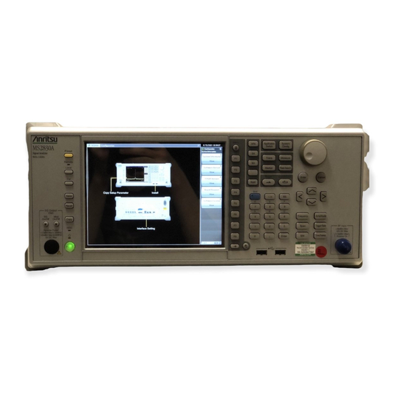
Chapter 3 Common Operations 3.4 Settings on Configuration Screen MS2830A system settings, and settings for system information display and common application functions can be configured in the Configuration screen. Press to display the Configuration screen. Figure 3.4-1 Configuration screen 3-16... -
Page 121: Display Description
Sets loading/unloading of applications. Application Switch Settings 3.4.5 “Application Switch Settings” Displays MS2830A system information. System Information 3.4.6 “System Information” Displays options installed in the MS2830A. Option Information 3.4.7 “Option Information” Sets file and data management. File Operation 3.4.8 “File Operation” Close Closes Configuration screen. -
Page 122: Interface Settings
Select the item to be set with the cursor, and then press (Set) to reflect the settings of that item. Refer to Section 1.3 “Interface Settings” in the MS2690A/MS2691A/MS2692A and MS2830A/MS2840A Signal Analyzer Operation Manual (Mainframe Remote Control) for details. Figure 3.4.2-1 Interface Settings screen... -
Page 123: Copy Settings
Settings on Configuration Screen 3.4.3 Copy Settings Pressing (Copy Settings) after displays the Copy Settings screen. Screen hard copy conditions can be set in this screen. Select the item to be set with the cursor, and then press (Set) to reflect the settings of that item. -
Page 124: System Settings
Chapter 3 Common Operations 3.4.4 System Settings Pressing (System Settings) after displays the System Settings screen. Select the item to be set with the cursor, and then press (Set) to reflect the settings of that item. Figure 3.4.4-1 System Settings screen Table 3.4.4-1 System Settings items Item Description... - Page 125 *1: This is displayed for MS2830A-040/041/043/044/045. *2: The switching is made according to the table shown below. *3: This is displayed when the MS2830A-062/066 Low Phase Noise Performance Option is installed. Figure 3.4.4-1 is an example for other than Option 040. For Option ≤...
- Page 126 Chapter 3 Common Operations Table 3.4.4-2 Attenuator Mode switching Electronic Atten Mechanical Option Frequency* Combined Atten Only ≤ 6 GHz 0 to 10 dB → M-ATT All M-ATT 12 to 40 dB → E-ATT 42 to 60 dB → M-ATT >...
-
Page 127: Application Switch Settings
Settings on Configuration Screen 3.4.5 Application Switch Settings Pressing (Application Switch Settings) after displays the Application Switch Settings function menu. The loading/unloading of applications can be set from this menu. Select the item to be set with the cursor, and then press (Set) to display the setting window of that item or start performing the setting. -
Page 128: System Information
Pressing (System Information) after displays the System Information menu. The MS2830A system information can be viewed from this menu. Pressing the function key corresponding to the system information to be viewed displays the window of the selected item. Table 3.4.6-1 System Information setting items... -
Page 129: Option Information
Settings on Configuration Screen 3.4.7 Option Information Pressing (Option Information) after displays the option screen. Information on options installed in the MS2830A can be viewed in this screen. 3.4.8 File Operation Pressing (File Operation) after displays the File Operation function menu. Data files can be managed from this menu. Pressing the function key corresponding to the data file to be managed displays the setting window of that item. -
Page 130: Software Install/Uninstall
(Software Install) to display the Software Install menu. Software can be installed and uninstalled to/from the MS2830A from this menu. Pressing the function key corresponding to the item to be set executes the selected item. Refer to Section 3.8 “Installing and Uninstalling” for details. - Page 131 When File Name Setting is set to Data + sequential, the file is automatically named ”Corr date_sequential number”. The Save Correction Table file is in CSV format and is saved in “[Selected drive]:\Anritsu Corporation\Signal Analyzer\User Data\Corrections\”. Up to 1000 files can be saved in the folder. Close Returns to the Configuration menu.
- Page 132 Chapter 3 Common Operations Recall Correction Table Pressing (Recall Correction Table) on Correction function menu displays the Recall Correction Table function menu. Those functions are used to recall the saved level frequency characteristics. Table 3.4.10-3 Recall Correction Table function menu Function Menu Display Function...
- Page 133 Settings on Configuration Screen As shown in Figure 3.4.10-1, if the frequency range over which the correction factors are entered is from Fa to Fb, displayed frequency ranges lower than Fa or higher than Fb have correction factors applied. The correction factor for frequencies lower than Fa is the same as that (La) for Fa and the correction factor for frequencies higher than Fb is the same as that (Lb) for Fb.
-
Page 134: Display Annotation
Chapter 3 Common Operations 3.4.11 Display Annotation When Display Annotation is OFF, the measurement target’s frequency and level included in the frequency-related settings, level-related settings, marker values, and measurement results are hidden from the application screen to avoid being seen. Press and then press . - Page 135 Settings on Configuration Screen Table 3.4.12-1 Calibration Alert function menu Function Item Description Specifies the trigger conditions for alerts. None No alert occurs. Temperature An alert occurs when a temperature goes outsides the specified thresholds based on the internal temperature measured at the last automatic calibration (SIGANA All).
- Page 136 For details of remote control commands to query status, refer to “Status of Calibration Alert” in Section 4.1 “Application Common Device Messages” in the MS2690A/MS2691A/MS2692A and MS2830A/MS2840A Signal Analyzer Operation Manual (Mainframe Remote Control) 3-32...
-
Page 137: Loading, Unloading, And Switching Applications
CAUTION • Applications registered to the Application Switch menu automatically enter an execution state when starting up the MS2830A. The more registered applications, the longer startup will take. • In the event running applications are suddenly ended while operating Windows, press... -
Page 138: Loading Applications
Chapter 3 Common Operations 3.5.1 Loading applications Applications can be loaded from the Configuration screen. <Procedure> After pressing , press (Application Switch Settings) to display the Application Switch Registration screen. Press (Load Application Select), select the applications to be loaded from the applications displayed in “Unloaded Applications” at the bottom part of the screen, and then press (Set). - Page 139 Loading, Unloading, and Switching Applications When registered correctly, the selected applications will be displayed in “Loaded Applications” at the top part of the screen. Figure 3.5.1-2 Application Switch Registration screen Press to display the Application Switch menu. Check that the loaded application is displayed in the menu.
-
Page 140: Unloading Applications
Chapter 3 Common Operations 3.5.2 Unloading applications Applications can be unloaded from the Configuration screen. <Procedure> After pressing , press (Application Switch Settings) to display the Application Switch Registration screen. Press (Unload Application Select), select the application to be unloaded from the applications displayed in “Loaded Applications” at the top part of the screen with the cursor, and then press (Set). - Page 141 Loading, Unloading, and Switching Applications When ended correctly, the selected applications will be displayed in “Unloaded Applications” at the bottom part of the screen. Figure 3.5.2-2 Application Switch Settings screen 3-37...
-
Page 142: Switching Applications
Chapter 3 Common Operations 3.5.3 Switching applications Applications to be operated can be switched in the Application Switch menu. Pressing displays the Application Switch menu screen. Pressing the function key corresponding to the application switches to the selected application screen. If the Application (Auto/Manual) setting is set to Auto as explained in 3.5.4 “Changing application layout”, the application you selected above is assigned. -
Page 143: Changing Application Layout
Loading, Unloading, and Switching Applications 3.5.4 Changing application layout The layout of applications can be changed as desired in the Application Switch menu. Set the application layout in the Configuration screen. <Procedure> After pressing , press (Application Switch Settings) to display the Application Switch Registration screen. - Page 144 Chapter 3 Common Operations Figure 3.5.4-1 Application Switch Function Position Edit screen Select the new position from the slots in the Function Position area or slot 5 in the Application Key area using the cursor keys and press Note: Slots 1, 2, and 3 in the Application Key area are automatically assigned to the Spectrum Analyzer, Signal Analyzer, and Signal Generator applications in accordance with the application key display on the front panel.
- Page 145 Loading, Unloading, and Switching Applications Figure 3.5.4-2 Application Switch Function Position Edit screen 3-41...
-
Page 146: Save And Recall Functions
USB memory (Parameter) and saving (Save) and recalling (Recall) of waveform data (Trace). Note: Use the USB memory supplied with the MS2830A. Using other USB memories may cause malfunction due to device incompatibility. 3.6.1 Saving parameters and waveform data With the MS2830A, the current setting conditions and waveform data can be saved to the internal hard disk or a USB memory. - Page 147 Save and Recall Functions Files will be saved in the following directory of the save target drive specified in (Device). \Anritsu Corporation\Signal Analyzer\User Data\ Parameter Setting Up to 1000 files can be saved in the folder. Saving waveform data <Procedure>...
-
Page 148: Recalling Parameters
Chapter 3 Common Operations 3.6.2 Recalling parameters With the MS2830A, settings can be restored by loading saved setting conditions from the internal hard disk or a USB memory. Recalling parameter setting conditions only of applications to be operated using Application Switch <Procedure>... - Page 149 Save and Recall Functions Recalling parameter setting conditions for all launched applications. <Procedure> Press from the Configuration, Signal Analyzer or Spectrum Analyzer screen to display the Recall function menu shown in Table 3.6.2-1. Press (Device) to change the location of saved setting parameters.
-
Page 150: Screen Hard Copy
A sequential number from 000 to 999 will be added to the file name. Files will be saved in the following directory of the save target drive specified in (Device). \Anritsu Corporation\Signal Analyzer\User Data\Copy Files Up to 1000 files can be saved in the folder. 3-46... -
Page 151: Simple Save&Recall
Save and Recall Functions 3.6.4 Simple Save&Recall This function allows parameter setting conditions to be recalled with little operations. Enabling Simple Save&Recall <Procedure> Press to display the Configuration screen. Press to display page 2 of the Configuration function menu. Press (Save&Recall Settings) to display the Save&Recall Settings function menu in Figure 3.6.4-1. - Page 152 Chapter 3 Common Operations Changing the parameter name (file name) to be saved from the default setting Pressing (Simple Save&Recall Name) in Figure 3.6.4-1 displays the Simple Save&Recall Name function menu in Figure 3.6.4-2. Up to ten parameter names can be registered in Simple mode. The default parameter names are PRM_1 to PRM_10.
- Page 153 Read-only. Pressing the function key stores the parameter saving file with the parameter name displayed. \Anritsu Corporation\Signal Analyzer\User Data\Parameter Setting The parameter settings can be saved in Standard mode on Open Save Menu. 3.6.1 “Saving parameters and waveform data”...
- Page 154 Chapter 3 Common Operations Simple Recall function Pressing in Simple mode displays the Simple Recall function menu in Figure 3.6.4-4. Figure 3.6.4-4 Simple Recall function menu Parameter names set with the Simple Save&Recall Name function menu are displayed on the function keys. The last saved date and time of the parameter saving file is displayed in the second line.
-
Page 155: Initializing
Initializing 3.7 Initializing This section describes how to initialize settings. 3.7.1 Preset Preset is a function for initializing application settings. Configuration screen settings are not initialized using this function. Similarly, there is no effect on user data saved to the internal hard disk. <Procedure>... -
Page 156: System Reset
(System Information) and then press to display page 2 of the System Information function menu. Press (System Reset) to execute System Reset. The MS2830A restarts automatically when System Reset is completed. Table 3.7.2-1 System Information function menu (2/2) Function Menu Display... -
Page 157: Installing And Uninstalling
<Procedure> Connect the USB memory to the PC, and then insert the installation disk. Select MS2830A Install from Install Software on the installation menu. Specify the root directory of the connected USB memory on the installation directory specification window (e.g., “E:\” when the USB memory is drive E). - Page 158 Chapter 3 Common Operations Installing software <Procedure> Remove the peripheral devices from the USB ports of the MS2830A, other than mouse and keyboard. Press to display the Configuration screen, and then press (Software Install) from page 2 of the Configuration function menu.
- Page 159 Installing and Uninstalling Figure 3.8.1-1 Software Install menu 3-55...
- Page 160 When pressing (Install), a message box asking "Do you install the selected application software license?" is displayed. Press Yes to start installation. The license becomes valid when the MS2830A is restarted after installation is completed. Figure 3.8.1-2 Software Install menu 3-56...
- Page 161 (Install), a message box asking "Do you install the selected SG Waveform license?" is displayed. Press Yes to start installation. The license will be valid when the MS2830A is restarted after installation is completed. Figure 3.8.1-3 Software Install menu 3-57...
-
Page 162: Uninstalling Software Or Licenses
Chapter 3 Common Operations 3.8.2 Uninstalling software or licenses The Install screen must be displayed in order to uninstall software or license files from the MS2830A. Note: Hardware licenses cannot be uninstalled. Uninstalling software <Procedure> Press to display the Configuration screen, and then press (Software Install) from page 2 of the Configuration function menu. - Page 163 Installing and Uninstalling Uninstalling software licenses <Procedure> Press to display the Configuration screen, and then press (Software Install) from page 2 of the Configuration function menu. The Software Install menu shown in Figure 3.8.2-2 is displayed. Press (Uninstall). The installation selection menu is displayed. Press (Software License).
- Page 164 Chapter 3 Common Operations Uninstalling waveform pattern licenses <Procedure> Press to display the Configuration screen, and then press (Software Install) from page 2 of the Configuration function menu. The Software Install menu shown in Figure 3.8.2-3 is displayed. Press (Uninstall). The installation selection menu is displayed.
-
Page 165: Chapter 4 Tutorial
Chapter 4 Tutorial This chapter describes the waveform display of the signal analyzer and spectrum analyzer. Spectrum Analysis Using Signal Analyzer ....4-2 4.1.1 Spectrum analysis ..........4-2 Spectrum Analysis Using Spectrum Analyzer ....4-6 4.2.1 Spectrum Analysis ..........4-6... -
Page 166: Spectrum Analysis Using Signal Analyzer
Chapter 4 Tutorial 4.1 Spectrum Analysis Using Signal Analyzer Option 006/106 is required to use the signal analyzer function. 4.1.1 Spectrum analysis The section describes the operation procedure for displaying input signal waveforms to the application screen of the signal analyzer. Input signal Figure 4.1.1-1 Front panel Example: Input Signal: Frequency: 1 GHz (CW) - Page 167 Spectrum Analysis Using Signal Analyzer <Procedure> Connect the input signal to the RF Input on the front panel of the MS2830A. Press then (Application Switch Settings) to display the Application Switch Settings menu. Press (Load Application Select) to select within the “Unload Applications”...
- Page 168 Chapter 4 Tutorial Table 4.1.1-1 Display items for Signal Analyzer Item Description This is the main function key of the signal analyzer. Basic parameter settings of the signal analyzer are configured here. Signal Analyzer Function Operation 2.1 “Display Description” Displays signal waveforms. Displays the center frequency, frequency span and other frequency parameters.
- Page 169 The waveform of the input signal is now displayed on the screen (see Figure 4.1.1-4). Figure 4.1.1-4 Waveform display using Signal Analyzer MS2830A/MS2840A Signal Analyzer Operation Manual Refer to the (Signal Analyzer Function Operation) for how to use the Signal Analyzer.
-
Page 170: Spectrum Analysis Using Spectrum Analyzer
Chapter 4 Tutorial 4.2 Spectrum Analysis Using Spectrum Analyzer 4.2.1 Spectrum Analysis This section describes the operation procedure for displaying input signal waveforms to the application screen of the spectrum analyzer. Input signal Figure 4.2.1-1 Front panel Example: Input Signal: Frequency: 1 GHz (CW) Level: −10 dBm... - Page 171 Spectrum Analysis Using Spectrum Analyzer <Procedure> Connect the input signal to the RF Input on the front panel of the MS2830A. Press then (Application Switch Settings) to display the Application Switch Settings menu. Press (Load Application Select) to select within the “Unload Applications”...
- Page 172 Chapter 4 Tutorial Table 4.2.1-1 Display items for Spectrum Analyzer Item Description This is the main function key of the spectrum analyzer. Basic parameter settings of the spectrum analyzer are configured here. Spectrum Analyzer Function Operation 2.1 “Display Description” Displays signal waveforms. Displays the start frequency.
- Page 173 The waveform of the input signal is now displayed on the screen (see Figure 4.2.1-4). Figure 4.2.1-4 Waveform display using Spectrum Analyzer MS2830A/MS2840A Signal Analyzer Operation Manual Refer to the (Spectrum Analyzer Function Operation) for how to use the Spectrum...
- Page 174 Chapter 4 Tutorial 4-10.
-
Page 175: Chapter 5 System
Chapter 5 System The MS2830A uses Microsoft Windows (hereinafter, referred to as “Windows”) as the operating system. Settings for Windows and the system can be operated by connecting a mouse and a keyboard. This section describes how to perform operations on Windows installed to the MS2830A and general notes. -
Page 176: Setting Windows
Chapter 5 System 5.1 Setting Windows The MS2830A is set to default settings at factory shipment so as to perform optimal measurements. Changing the Windows settings is outside the scope of operation warranty. In addition, performance may drop or functions may not operate correctly when Windows settings are changed. -
Page 177: Displaying Windows Desktop
Windows Taskbar. Mouse Click the “Minimize” button located in the upper right corner of the application window of the MS2830A. Minimizing all applications displays the Desktop. Keyboard Pressing the [Windows] key + [D] key minimizes all windows and... -
Page 178: Setting Control Panel
Program and Hardware • Do not delete the installed devices or update/delete the drivers. • The MS2830A may not operate normally due to conflicts with device drivers when new hardware is added. • Do not update or remove programs installed at the factory. - Page 179 • Firewall settings are set to Off at the factory. When settings are set to On, Windows Firewall displays a dialog box asking if you want to block the applications of the MS2830A at the next startup time. Be sure to click Unblock.
-
Page 180: Using External Display
5.1.3 Using external display An external display can be connected to the VGA connector on the rear side of the MS2830A, to display screens of the MS2830A and show multiple displays. The following describes the operation procedure for this function. - Page 181 When using only an external display • Operating Mode Single Display • Primary Display (Connected external display) When displaying the same content on each of the MS2830A display and external display • Operating Mode Clone Display • Primary Device Built-in Display (MS2830A display) •...
-
Page 182: General Notes
• Enable or operate a Windows program service that is disabled or stopped at factory. e.g.) Transfer files by FTP while the MS2830A is running. In addition to the above, note the below. • The MS2830A may not work properly when the registries are changed. -
Page 183: Storage Device Configuration
• Do not change the partition configuration. Doing so may affect system operation. • Do not format the hard disk of the MS2830A. Besides the above, data for system recovery is stored within this hard disk. Recovery may become inoperable when the hard disk is formatted. -
Page 184: System Recovery Functions
The MS2830A comes with factory-installed recovery software, Phoenix Recover Pro or Paragon Drive Backup. To confirm the installed recovery software, start the MS2830A, and press the F4 key on the BIOS screen to start the recovery software. <Procedure>... -
Page 185: Phoenix Recover Pro
“Phoenix Recover Pro”. Restore System drive (partition) only This function restores only Volume C, in which Windows, application software, and files required for operations of the MS2830A are stored, to the factory shipment status. Restore entire hard disk This function restores Volume C and Volume D to the factory shipment status. -
Page 186: Paragon Drive Backup
“Paragon Drive Backup”. Type: Partition This function restores only Volume C, in which Windows, application software, and files required for operations of the MS2830A are stored, to the factory shipment status. Type: Disk This function restores Volume C and Volume D to the factory shipment status. -
Page 187: Performance Test
Chapter 6 Performance Test This chapter describes measurement devices, setup methods, and performance test procedures required for performing performance tests as preventive maintenance of the MS2830A. Overview of Performance Test ........6-2 6.1.1 Performance test ..........6-2 6.1.2 Performance test items and instruments used . 6-3 Performance Test Items .......... -
Page 188: Overview Of Performance Test
6.1 Overview of Performance Test 6.1.1 Performance test Performance tests are performed as part of preventive maintenance in order to prevent the performance of the MS2830A from being degraded before it occurs. Use performance tests when required for acceptance inspection, routine inspection and performance verification after repairs. -
Page 189: Performance Test Items And Instruments Used
Overview of Performance Test 6.1.2 Performance test items and instruments used Table 6.1.2-1 lists measuring instruments used or performance tests. Table 6.1.2-1 List of measuring instruments for performance test Name of Recommended Test Items Required Performance Device (Model Name) Display frequency accuracy •... - Page 190 • Measurement power range –67 to +20 Power sensor (MA2444D) ± • Mainframe accuracy 0.02 dB Display average noise level • Frequency range: DC to 43 GHz MS2830A-040/041/043/044 • VSWR: 1.2 or less Standard terminator (28N50-2) • 50 Ω MS2830A-045 Standard terminator...
-
Page 191: Performance Test Items
Performance Test Items 6.2 Performance Test Items Warm up the subject testing device and measuring instruments for at least 30 minutes except where directed, in order to stabilize them sufficiently before running performance tests. Demonstrating maximum measurement accuracy requires, in addition to the above, conducting performance tests under ambient temperatures, little AC power supply voltage fluctuations, as well as the absence of noise, vibrations, dust, humidity or other problems. -
Page 192: Display Frequency Accuracy
6.2.1 Display frequency accuracy The known frequency which is the reference for the display frequency, is added to the MS2830A as shown in (3) then the center frequency and frequency span are set from the front panel. The difference between the... - Page 193 Set the frequency span (10 kHz) and the resolution bandwidth (300 Hz) corresponding to the center frequency (500 MHz) shown in the Display Frequency Accuracy table of Appendix A to the MS2830A. Read the marker frequency value (MKR value) shown on the screen,...
-
Page 194: Frequency Span Display Accuracy
Set to the signal generator the frequencies of the first div and ninth div from the left edge of the screen as shown in (3), and read their frequency difference to obtain the span accuracy. (1) Test target standards MS2830A • Frequency span accuracy: ±0.2% (2) Measuring instrument for tests •... - Page 195 Frequency Span Display Accuracy table of Appendix A. Measure the spectrum waveform peak frequency by using the marker function of the MS2830A. This frequency is set to f ’. Set to the frequency of output frequency f of the MG3691C/92C/94C (1800.004 MHz), and then measure the spectrum waveform peak...
-
Page 196: Single Sideband Noise Level
Chapter 6 Performance Test 6.2.3 Single sideband noise level Set the resolution bandwidth to a specific value then input a signal with a single sideband noise level far smaller than the subject test device. Test how far the dB drops from the peak point for a noise level which is distanced by a specific frequency from the spectrum waveform peak point at this time. - Page 197 Figure 6.2.3-2 Signal sideband noise level (4) Notes on test Perform the test at an ambient temperature of 18 to 28°C and after warming up for at least 30 minutes. (5) Test procedure Start the application Spectrum Analyzer of the MS2830A. Press Press (Preset). Press and then (SIGANA All).
- Page 198 Set Marker to Normal and Marker Result to Peak. Set the center frequency of the Marker zone to 500 MHz, and adjust the HP8665B output level so that the input level to the MS2830A is 0 dBm±0.06 dB. 10. After setting Marker to Delta, set Marker Result to Density.
-
Page 199: Rf Frequency Characteristics
(3.5 GHz ≤ frequency ≤ 6 GHz, Frequency Band Mode: Spurious) With MS2830A-044/045 installed, Without MS2830A-008/108/068/168, or with Preamplifier turned off, Without MS2830A-067/167 or with Microwave Preselector Bypass turned off and after Preselector Auto Tune is done: ±1.0 dB (9 kHz ≤ Frequency < 300 kHz) ±0.35 dB... - Page 200 (2) Measuring instrument for tests • Signal generator (MG3710A) [Less than 6 GHz] • Signal generator (MG3691C/92C/94C) [6 GHz or more] MG3691C is valid for MS2830A-041 and MG3692C is valid for MS2830A-043. • Power meter (ML2488B) • Power sensor (MA2444D)
-
Page 201: Power Meter
Performance Test Items (3) Setup Buffer Out Ref Input 10 MHz 10 MHz MS2830A MG3710A or MG3691C/92C RF Input RF Output Attenuator Attenuator (3 dB) (3 dB) Calibrator Power meter (ML2488B) Power sensor Anritsu MS2487A (MA2444D) At initial setup, connect the MG3710A and MA2444D. - Page 202 (calibration value) on the power meter. Measuring RF frequency characteristics Connect the MG3710A (MG3691C/92C/94C) RF output to the RF input of the MS2830A using the coaxial cable. Start the application Spectrum Analyzer of the MS2830A. Press of the MS2830A.
- Page 203 10. Calculate the RF frequency characteristics, using the calibration value of the MG3710A (MG3691C/92C/94C) and the indicated value on the MS2830A. RF frequency characteristics = Indicated value on MS2830A – calibration value (indicated value on power meter) 11. Set this instrument shown as below, only when Preamplifier...
-
Page 204: Display Average Noise Level
VBW = 1 Hz (Video Average), detection mode: Sample, input attenuator 0 dB, at 18 to 28°C, Frequency Band Mode: Normal. MS2830A With MS2830A-040/041/043 installed, Without MS2830A-062/066, and without MS2830A-008/108 or with Preamplifier turned off: – ≤ 134 dBm/Hz (100 kHz) ≤... - Page 205 Performance Test Items With MS2830A-062/066 installed, and without MS2830A-008/108 or with Preamplifier turned off: ≤ –133 dBm/Hz (100 kHz) ≤ –143 dBm/Hz (1 kHz) ≤ –152 dBm/Hz (30 MHz≤Frequency<1 GHz) ≤ –150 dBm/Hz (1 GHz≤Frequency<2.4 GHz) ≤ –147 dBm/Hz (2.4 GHz≤Frequency<3.5 GHz) With MS2830A-041/043 installed: ≤...
- Page 206 ≤ –146 dBm/Hz (26.5 GHz < Frequency ≤ 34 GHz) ≤ –144 dBm/Hz (34 GHz < Frequency ≤ 40 GHz) ≤ –140 dBm/Hz (40 GHz < Frequency ≤ 43 GHz) Without MS2830A-067/167 and with MS2830A-068/168 and with Preamplifier turned off: – ≤ 134 dBm/Hz (100 kHz) –...
- Page 207 ≤ –135 dBm/Hz (34 GHz < Frequency ≤ 40 GHz) ≤ –132 dBm/Hz (40 GHz < Frequency ≤ 43 GHz) With MS2830A-067/167, and with MS2830A-068/168, or with Preamplifier turned off: ≤ –143 dBm/Hz (6 GHz < Frequency ≤ 13.5 GHz) ≤...
- Page 208 MS2830A. Press (Preset). Press and then (SIGANA All). Terminate the RF input with the standard terminator. Set as follows for the MS2830A (time domain mode). Center Freq 100 kHz Span 0 Hz Reference Level −100 dBm 1 kHz...
- Page 209 Performance Test Items 13. Using the burst average measurement function, set the Start Time and Stop Time parameters as follows and measure the level. Start Time 100 ms Stop Time 900 ms 14. The (Burst average measurement value [dBm] −30 dB) will be the display average noise level (dBm/Hz).
-
Page 210: Second Harmonic Wave Distortion
For the test method point, apply a distortion signal (at least 20 dB) lower than the internal harmonic wave of the MS2830A then measure the level difference between the fundamental wave and the second harmonic wave. - Page 211 ≤ –70 dBc (1.75 GHz ≤ Input frequency ≤ 3 GHz, Frequency Band Mode: Spurious) ≤ –70 dBc (3 GHz ≤ Input frequency ≤ 6.75 GHz) With MS2830A-008/108/068/168 and with Preamplifier turned on, and at Attenuator Mode = Mechanical Atten Only: At mixer input level –45 dBm ≤...
- Page 212 Appendix A. If LPF attenuation is insufficient, use LPF in 2 stages. Set the output frequency of the MG3710A and center frequency of the MS2830A, and reference level, according to the Second Harmonic Wave Distortion table in Appendix A. 6-26...
- Page 213 Performance Test Items Adjust the output level of the signal generator so as to get the peak point of the spectrum waveform into the range of −±0.06 dB. 10. Press to perform a peak search. Set so as to include the signal trace peak point to the zone marker.
- Page 214 Chapter 6 Performance Test Figure 6.2.6-3 Second harmonic wave 13. Repeat Steps 7 to 12, according to the Second Harmonic Wave Distortion table in Appendix A. 14. When the Preamplifier option is installed Press and turn on the preamplifier by pressing (Pre-amp).
-
Page 215: Chapter 7 Power Meter
Chapter 7 Power Meter This chapter describes basic operations of the power meter functions. Power Meter ..............7-2 Display Description ............7-3 Function Menu .............. 7-5 7.3.1 Setting the frequency........7-6 7.3.2 Level setting ............. 7-7 7.3.3 Measure ............7-9 7.3.4 Accessory ............ -
Page 216: Power Meter
Chapter 7 Power Meter 7.1 Power Meter You can connect a USB power sensor to the MS2830A and read the measurement values. Preparation For the setup procedure of the application software for this function, refer to Section 3.8 “Installing and Uninstalling” and Section 3.5 “Loading, Unloading, and Switching Applications.”... -
Page 217: Display Description
Display Description 7.2 Display Description Press to display the Application Switch function menu. Then, select the Power Meter, and you can display the power meter application main screen and the function menu. Figure 7.2-1 Power meter application main screen... -
Page 218: Display Description
Chapter 7 Power Meter Table 7.2-1 Parameters on the power meter application main screen Display Description Application software name Power Meter The name of the synchronizing application is displayed in parentheses. COM Port number (xx) to which the USB COMxx power sensor is connected. -
Page 219: Function Menu
Function Menu 7.3 Function Menu Press when the Power Meter function to display the Power Meter function menu. Table 7.3-1 Power Meter function menu Function Menu Display Function Opens the Frequency function menu. Frequency 7.3.1 “Setting the frequency” Opens the Amplitude function menu. Amplitude 7.3.2 “Level setting”... -
Page 220: Setting The Frequency
Chapter 7 Power Meter 7.3.1 Setting the frequency In the Frequency function menu, you can set the calibration factor frequency of the USB power sensor. Press (Frequency) in the Power Meter function menu to display the Frequency function menu. Table 7.3.1-1 Frequency function menu Function Menu Display Function... -
Page 221: Level Setting
Function Menu 7.3.2 Level setting Press (Amplitude) or in the Power Meter function menu to display the Amplitude function menu. Table 7.3.2-1 Amplitude function menu Function Menu Display Function Range Opens the Range function menu. Offset Turns on and off the level offset function. (On/Off) Offset Value Sets the level offset value. - Page 222 When this function is used, the displayed power sensor value is offset with the value specified in the Offset Value dialog box. It is used when the path loss or gain from the MS2830A to DUT is corrected. [Power sensor reading after offset]...
-
Page 223: Measure
Function Menu 7.3.3 Measure Press (Measure) or in the Power Meter function menu to display the Measure function menu. The Measure function menu items depend on whether the Power Meter application synchronizes with the other application or not. When not synchronizing with any applications Table 7.3.3-1 Measure function menu Function Menu Display... -
Page 224: Accessory
Chapter 7 Power Meter 7.3.4 Accessory Press (Accessory) in the Power Meter function menu to display the Accessory function menu. Table 7.3.4-1 Accessory function menu Function Menu Display Function Title Sets the title character string. Turns on and off the title character Title (On/Off) string display. -
Page 225: Power Meter
Function Menu 7.3.5 Power Meter Press (Power Meter) in the Measure function menu. In the Power Meter menu, you can set the measurement that is performed by using the USB power sensor. Table 7.3.5-1 Power Meter function menu Function Menu Display Function Turns on and off the function of averaging the Average... - Page 226 (Zero Sensor) in the Power Meter function menu to execute the zeroing. When you execute the function, a progress dialog box appears. Please do not operate the MS2830A during the zeroing. Figure 7.3.5-1 “Power Meter zeroing” dialog box (Progress) If the zeroing fails, the following dialog box appears.
- Page 227 <Procedure> 1. Plug in the USB power sensor connector to the USB port of the MS2830A Signal Analyzer. 2. Turn off the RF output of DUT (device under test) in advance. Connect the RF Input connector of the power sensor to the RF output terminal of DUT.
-
Page 228: Aperture Setting
Chapter 7 Power Meter 7.3.6 Aperture Setting Press (Aperture Setting) in the Power Meter function menu to display the Aperture Setting menu. Refer to the “Aperture Time” section and the “Measurement Considerations” section of your power sensor chapter in “USB Power Sensors MA241xxA and PowerXpert User Guide”... -
Page 229: Initialization
Initialization 7.4 Initialization 7.4.1 Preset Power Meter function is a kind of application. For the presetting procedure, refer to Section 3.7.1 “Preset.” 7.4.2 Default value list This section lists the default values of the Power Meter function. Frequency 1 GHz Level Offset State Level Offset Value 0.00 dB... - Page 230 Chapter 7 Power Meter 7-16.
-
Page 231: Ber Measurement Function
BER Measurement Function This chapter describes the operation methods for the BER measurement function of the MS2830A-026/126. Note: This application is available only when MS2830A-026/126 is installed. Outline of BER Measurement ........8-2 Display Description ............8-5 BER Measurement Function Menu....... 8-9 Connecting MS2830A-026/126 to External System ... -
Page 232: Outline Of Ber Measurement
Chapter 8 BER Measurement Function 8.1 Outline of BER Measurement The MS2830A-026/126 can measure the bit error rate (BER) of signals incoming from external systems. By pressing the Application Switch and then BER Test, the MS2830A-026/126 can be switched to BER measurement mode. - Page 233 Outline of BER Measurement Measured pattern PN9, PN11, PN15, PN20, PN23, ALL0, ALL1, repetition of 01, PN9Fix, PN11Fix, PN15Fix, PN20Fix, PN23Fix, and user-defined patterns Measurement bit count 1000 to 4294967295 bits (2 − 1 bits) Measurement error bit count 1 to 2147483647 bits (2 −...
- Page 234 × 2) consecutive bits for a PN signal that includes random errors. These probabilities thus can be referred to as the probabilities that the MS2830A-026/126 synchronizes with a PN signal at a certain error rate in one cycle.
-
Page 235: Display Description
Display Description 8.2 Display Description This section describes the BER measurement function display items. [1] Data Type [2] Count Mode [3] Measure Mode [4] Status [5] Error [6] Syncloss Count [7] Error Rate [8] Error Count [9] Measured bit Figure 8.2-1 BER main screen... -
Page 236: Display Description
Chapter 8 BER Measurement Function Table 8.2-1 Display items in BER measurement mode Display Description Displays the names of data selected on the list selection popup screen. Characters cannot be directly entered. Displays the data set on the data input screen. When User Pattern is selected in the data settings, parameters related to the loaded User Pattern are displayed. - Page 237 Display Description Table 8.2-2 Display items in Measure Information area Display Description Status Displays Stop, Synchronizing, and Measuring. These messages light up when the following errors occur. BitError: Error bit occurrence SyncLoss: SyncLoss occurrence ClockError: Input clock signal failure EnableError: Input enable signal failure Displays OverflowDataCount or OverflowSyncLoss when the following errors...
- Page 238 Chapter 8 BER Measurement Function Table 8.2-3 Error rate display Display Description Error Rate Displays the error rate. Error Count Displays the error count. Displays the number of measured bits. Error Rate display Error Rate may be displayed in either floating-point form or fixed-point percentage, which complies with the following rules: •...
-
Page 239: Ber Measurement Function Menu
BER Measurement Function Menu 8.3 BER Measurement Function Menu This section describes the main function menu on the BER measurement screen. Page Page 1 Figure 8.3-1 Main function menu... - Page 240 Chapter 8 BER Measurement Function Table 8.3-1 Top function menu Menu Display Function Starts BER measurement. Measure Start 8.5 “Performing BER Measurement” Stops BER measurement. Measure Stop 8.5 “Performing BER Measurement” Clears the count operation. Count Clear 8.5 “Performing BER Measurement” Selects the data type.
-
Page 241: Connecting Ms2830A-026/126 To External System
Refer to Table 3.1.1-1 “AUX Connector” for details on pin assignment. Figure 8.4-1 Input connector If the enable signal is not used, set “Enable Active” to “Disable.” Change the settings of the MS2830A-026/126 in accordance with the specifications of the input signal. 8.7 “Setting Input Interface”... -
Page 242: Performing Ber Measurement
BER measurement <Procedure> Input the signals from the external system according to the instructions in Section 8.4 “Connecting MS2830A-026/126 to External System.” Select the data type. Press (Data Type) to display the Data Type selection window. Move the cursor to the pattern to be used for the measurement and press (Set) to select a pattern. - Page 243 Performing BER Measurement Select BER measure mode. Press (Measure Mode) to display the Measurement Mode selection window. Move the cursor to the desired measurement mode and press (Set) to select it. One of the following three types can be selected for the measurement mode: Continuous Performs the measurement continuously for the...
- Page 244 Chapter 8 BER Measurement Function When “Endless” is selected for the measurement mode, the count mode (Count Mode), data bit (Data), and the display of error bit (Error) setting items is darkened. Figure 8.5-3 When Single or Continuous is selected Figure 8.5-4 When Endless is selected 8-14...
- Page 245 Performing BER Measurement Select the measurement termination condition. This item cannot be set when Endless is selected. Press (Count Mode) to display the Measurement termination condition setup window. Move the cursor to the desired measurement termination condition and press (Set) to select it. Either of the following two types can be selected for the measurement termination condition: Data...
- Page 246 Chapter 8 BER Measurement Function Figure 8.5-6 Measurement bit count setup window Measurement bit count setting range: 1000 to 4294967295 bits Set the measurement error bit count. This item cannot be set when Endless is selected. When Count Mode is set to Error, the value in Error Bit can be changed.
- Page 247 Performing BER Measurement Configure settings for the automatic resynchronization function. The automatic resynchronization function can be enabled/disabled and the SyncLoss error judgment condition can be set. Refer to the following section for details on the settings. 8.6 “Setting Automatic Resynchronization Function” 8.
- Page 248 Option 077/177 Analysis Bandwidth Extension to 62.5 MHz, or Option 078/178 Analysis Bandwidth Extension to 125 MHz is installed in the MS2830A. • Switching the frequency span of the signal analyzer function to 31.25 MHz or less (lower) and to 50 MHz or more (upper).
- Page 249 Performing BER Measurement Display in each BER measurement mode The following figures show the difference in the measurement display among BER measurement modes. For the progress state and error rate display during measurement, see Figure 8.2-1 “BER main screen”. Measurement Mode: Continuous The Measured result is not updated during measurement.
- Page 250 Chapter 8 BER Measurement Function Note: The measurement results may not be displayed correctly when “synchronizing” and “measuring” appear in the Status field alternately and repeatedly. In that case, check the settings and input signals and restart the measurement. Count Clear operation The operation when (Count Clear) is pressed is described below.
- Page 251 Performing BER Measurement Measurement starts. Measurement ends. Received bit display 64388 bits Figure 8.5-10 Count Clear operation When measurement is stopped (Stop): The received bit count, error rate, and progress state displays are cleared. 8-21...
-
Page 252: Setting Automatic Resynchronization Function
Chapter 8 BER Measurement Function 8.6 Setting Automatic Resynchronization Function This section describes the settings for the automatic resynchronization function of BER measurement. Figure 8.6-1 Resync Condition setup screen Setting procedure for automatic resynchronization function Press (Resync Condition) from page 2 of the main function menu to perform various settings for the automatic resynchronization function of BER measurement. - Page 253 Setting Automatic Resynchronization Function [3] at SyncLoss Sets whether to clear the measurement bit count when SyncLoss occurs. Count Clear Clears the measurement bit count to 0. Count Keep Retains the measurement bit count. Details of Auto Resync The difference in operation when Auto Resync is set to On and Off is described below.
- Page 254 MS2830A and the Auto Sync operation supported in the MP1201C and MD6420A are described below. Details of Auto Resync operation The details of the Auto Resync operation supported in the MS2830A are as follows. Auto Resync On Synchronization is executed at the start of measurement, and the measurement is started when synchronization is established.
- Page 255 Setting Automatic Resynchronization Function Auto Resync Off Synchronization is executed at the start of measurement, and the measurement is started when synchronization is established. SyncLoss is not detected during measurement. Measurement Synchronization starts. is established. Synchronizing Measuring Figure 8.6-3 Auto Resync Off Details of Auto Sync operation The Auto Sync operation supported in the MP1201C and MD6420A is as follows.
- Page 256 Chapter 8 BER Measurement Function Auto Sync Off Measurement is performed on the assumption that synchronization is established at the start of measurement. SyncLoss is not detected during measurement. Starts measurement. Measuring Figure 8.6-5 Auto Sync Off Note: To obtain a BER curve, set Auto Sync to On so as to establish synchronization with superior S/N, and then switch Auto Sync to Off to change S/N and start the measurement.
-
Page 257: Setting Input Interface
Setting Input Interface 8.7 Setting Input Interface This section describes the settings of the input interface used for BER measurement. BER measurement will not stop even if this setting is changed. Figure 8.7-1 Input interface setup screen Input interface setting procedure Press (BER Interface) from page 2 of the main function menu to set the input interface to be used for BER measurement. - Page 258 Chapter 8 BER Measurement Function 8.8 Setting PN_Fix Pattern Special PN patterns called PN_Fix patterns can be used for BER measurement. Details of PN_Fix pattern A PN_Fix pattern consists of a repetitive part of a PN pattern and a PN pattern shorter than one period.
-
Page 259: Setting Pn_Fix Pattern
Setting PN_Fix Pattern [1] PN Pattern Initial Sets the initial bit pattern of the PN_Fix pattern. Figure 8.8-2 PN Pattern Initial setup screen 1. Enter the initial bit pattern of the PN_Fix pattern. Enter the initial bit pattern in binary. Use the numeric key pad (only 0 and 1) to enter numeric values. - Page 260 Chapter 8 BER Measurement Function Setting range: 96 to 134217728 bits <Note on setting PN_Fix> When the initial value of PN_Fix is set to All0, the following signals are output: PN9, PN11, PN20: ALL0 signal PN15, PN23: ALL1 signal Synchronization establishing condition for PN_Fix patterns The synchronization establishing conditions for the PN_Fix pattern are described below.
- Page 261 Setting PN_Fix Pattern Measurement [1] No error detection for 18 bits starts. (PN9 synchronization establishment condition) Incomplete (511 bits) (511 bits) (200 bits) One cycle of PN9Fix Discontinuous point [2] Discontinuous point detection Incomplete (511 bits) (511 bits) (200 bits) [3] No error detection Discontinuous point for 9 bits...
- Page 262 PN9 signal of the communication channel. In the case of a signal generator that uses an arbitrary waveform generator such as the MS2830A, however, the number of patterns that can be stored in the waveform memory may decrease or exceed the...
- Page 263 Setting PN_Fix Pattern Clock,Data, Enable Waveform pattern RF signal (PN_Fix data) Figure 8.8-6 BER measurement using PN_Fix data 8-33...
-
Page 264: Setting User-Defined Pattern
A user-defined pattern can be created in text file format using a PC. That file is then loaded from USB memory or the internal hard disk of the MS2830A. Create the file as described below and set the extension as “bpn.”... - Page 265 Setting User-defined Pattern The following shows examples of file content that can be loaded. Example 1: #20070216 Marked by Anritsu Co. 0010 0111 0110 0011 0000 1111 0101 Example 2: #UserPattern Start 0000 0000 1111 1111 #mark001 0101 0101 #mark002...
- Page 266 Chapter 8 BER Measurement Function Displaying user-defined patterns To use a user-defined pattern, select UserDefine for Data Type. The parameters for the loaded user-defined pattern will be displayed on the main screen. Blanks will be displayed if no user-defined pattern is loaded.
- Page 267 Loads user-defined patterns from the USB Load memory or the internal hard disk of the User Pattern MS2830A. Selects the media among the USB memory and Device internal hard disk from which user-defined patterns are to be loaded.
- Page 268 Chapter 8 BER Measurement Function Procedure for loading User-defined patterns This section describes the procedure for loading user-defined patterns. <Procedure> Press (Device) to select among the USB memory and internal hard disk, the device in which user-defined pattern files to be loaded are stored.
- Page 269 Either of the following messages will be displayed if the length of the user-defined pattern is out of the range supported by the MS2830A-026/126. If shorter than 8 bits: “Bit pattern is too short.”...
- Page 270 Chapter 8 BER Measurement Function Synchronization establishing condition setting for user-defined patterns When the user-defined pattern is loaded, set the conditions for synchronization establishment. Set the start bit and the length of the section to be used for judging the synchronization establishment.
- Page 271 Setting User-defined Pattern Move the cursor to Sync Position Length and use the numeric key pad, rotary knob, or to set the length of the section judged for synchronization establishment. Range: 8 to 1024 8-41...
-
Page 272: Description Of Ber Measurement Operation
Chapter 8 BER Measurement Function 8.10 Description of BER Measurement Operation This section describes the BER measurement operation, from synchronization to measurement termination. When Auto Resync is set to Off The following flowchart summarizes BER measurement operation when Auto Resync is set to Off. In this mode, the error rate is checked immediately after synchronization in order to judge whether synchronization is correctly established. - Page 273 8.10 Description of BER Measurement Operation Start of BER measurement Synchronization Establishing synchronization* Display: Synchronization Synchronization failure Synchronization check* Synchronization check is passed Count operation Display: Condition is not met Measuring (Continuing) Termination condition check* Condition is met (Terminating) Measurement stop Display: Stop Measure Mode...
- Page 274 Chapter 8 BER Measurement Function *1: The error rate is not checked if the measurement is terminated with a measurement bit count of less than 1000 bits. The measured values may be incorrect in this event. *2: If the error rate when the measurement bit count reaches 1000 bits is 30% or higher, it is judged as a synchronization failure.
- Page 275 8.10 Description of BER Measurement Operation When Auto Resync is set to On The following flowchart summarizes the BER measurement operation when Auto Resync is set to On. In this mode, resynchronization is automatically executed when SyncLoss occurs. 8-45...
- Page 276 Chapter 8 BER Measurement Function Start of BER measurement Display: Synchronization Synchronization Establishing synchronization Reception of bits required for SyncLoss condition check* SyncLoss check SyncLoss* Display: Measuring Count operation Condition is not met (Continuing) Termination condition check* Condition is met. (Terminating) Measurement stop Display:...
- Page 277 8.10 Description of BER Measurement Operation *1: The SyncLoss condition check is not executed until the number of received bits reaches the number of bits set as the denominator of the SyncLoss threshold set in [Threshold] on the Resync Condition Setup screen.
- Page 278 Chapter 8 BER Measurement Function 8-48.
-
Page 279: Maintenance
Chapter 9 Maintenance This chapter describes cautions related to daily maintenance, storage, and shipping of the MS2830A, as well as the calibration procedure to be used as preventive maintenance. Daily Maintenance and Storage........9-2 9.1.1 Daily maintenance ..........9-2 9.1.2 Cautions on storage MS2830A for extended period .......... -
Page 280: Daily Maintenance And Storage
Chapter 9 Maintenance 9.1 Daily Maintenance and Storage 9.1.1 Daily maintenance Before daily maintenance of the MS2830A, be sure to turn the power off and unplug it from the AC outlet. Panel surface dirt When surface dirt is noticeable, after the MS2830A has been used in a... -
Page 281: Cautions On Storage Ms2830A For Extended Period
90% or higher Recommended storage conditions It is recommended that the MS2830A be stored in a place that meets the ambient conditions suggested above, plus the following conditions, if it is not to be used for a long period of time: •... -
Page 282: Repackaging And Transporting When Returning Product
The following describes cautions on transporting the MS2830A. 9.2.1 Repackaging Repack the MS2830A in the packing material (box) in which it had been delivered. If the packing material has been scrapped or damaged, repack the MS2830A in the following manner: Wrap the MS2830A in plastic or a similar material. -
Page 283: Calibration
Even if the MS2830A is functioning normally, calibrate it periodically to maintain its performance. Calibrating the MS2830A once or twice a year is recommended. If the MS2830A fails to meet specifications after calibration, contact an Anritsu Service and Sales office. -
Page 284: Calibrating Frequencies Using Frequency Counter
Use a frequency standard radio signal (signal synchronized with a standard radio signal or with a rubidium atom standard device) offering enough accuracy higher than the reference oscillator installed in the MS2830A. Table 9.3.3-1 Calibration specifications Reference Oscillator Aging Rate... - Page 285 (Reference In) of frequency counter. Connect the reference signal output (Buffer Out) located on the rear panel of the MS2830A to the reference signal input connector (Reference In) of Signal Generator. Connect the RF output connector 1 of signal generator to input 1 connector of the frequency counter.
- Page 286 Chapter 9 Maintenance 9-8.
-
Page 287: Appendix A Performance Test Result Form
Appendix A Performance Test Result Form Performance Test Result Form Test Report No. Location Date Test person in charge Equipment Name: MS2830A Signal Analyzer Serial No. Ambient °C temperature Power Relative frequency humidity Remarks... - Page 288 30 k 1799987998 1800012002 10 M 100 k 1799973998 1800026002 20 M 100 k 1799952998 1800047002 3600 M 1792289998 1807710002 Display frequency accuracy test, only for MS2830A-041/043 Setting example Minimum Maximum Center Frequency Resolution Result [Hz] [Hz] freq span bandwidth [Hz]...
- Page 289 Performance Test Result Form Display frequency accuracy test, only for MS2830A-043 Setting example Minimum Maximum Center Frequency Resolution Result [Hz] [Hz] freq span bandwidth [Hz] [Hz] [Hz] 6750 M 10 k 6749999962 6750000038 50 k 6749999743 6750000257 30 k 6749994298...
- Page 290 Appendix A Performance Test Result Form Display frequency accuracy test, only for MS2830A-044/045 Setting example Minimum Maximum Center Frequency Resolution Result [Hz] [Hz] freq span bandwidth [Hz] [Hz] [Hz] 500 M 10 k 499999962 500000038 200 k 499999428 500000572 30 k...
- Page 291 Performance Test Result Form Display frequency accuracy test, only for MS2830A-044 Setting example Minimum Maximum Center Frequency Resolution Result [Hz] [Hz] freq span bandwidth [Hz] [Hz] [Hz] 22450 M 10 k 22449999956 22449999956 200 k 22449999422 22449999422 30 k 22449994292...
- Page 292 Appendix A Performance Test Result Form Frequency Span Display Accuracy MS2830A-040/041/043 frequency span display accuracy test Measurement Settings for MS2830A Results ′ − f ′ ) Signal Generator Center Frequency / 0.8 Freq Span / SPAN × 100 [Hz]...
- Page 293 Performance Test Result Form MS2830A-044/045 frequency span display accuracy test Measurement Settings for MS2830A Results ′ − f ′ ) Signal Generator Center Frequency / 0.8 Freq Span / SPAN × 100 [Hz] [Hz] [Hz] [Hz] [Hz] − 100 [%]...
- Page 294 250 k 10 k –115 +0.5 2.5 M 100 k –133 +0.5 RF Frequency Characteristics Frequency Band Mode: Normal (MS2830A-040/041/043 only) Without MS2830A-008/108 or with Preamplifier turned off: Result Calibration Measured Freq. Minimum Maximum Uncertainty value value Measured value –...
- Page 295 Performance Test Result Form Frequency Band Mode: Normal (MS2830A-040/041/043 only) With MS2830A-008/108 and Preamplifier turned on: Result Calibration Measured Freq. Minimum Maximum Uncertainty value value Measured value – [Hz] [dB] [dB] [dB] [dBm] [dBm] Calibration value [dB] 50 M –0.65 +0.65...
- Page 296 Appendix A Performance Test Result Form Frequency Band Mode: Normal (MS2830A-044/045 only) With MS2830A-008/108 and Preamplifier turned on: Result Measured Freq. Calibration Minimum Maximum Uncertainty Measured value – value [Hz] value [dBm] [dB] [dB] [dB] Calibration value [dBm] [dB] 10 M –0.65...
- Page 297 Performance Test Result Form Frequency Band Mode: Normal (MS2830A-044/045 only) With MS2830A-068/168 and Preamplifier turned on: Without MS2830A-067/167, with Microwave Preselector Bypass turned off and after Preselector Auto Tune is done: Result Measured Freq. Calibration Minimum Maximum Uncertainty Measured value –...
- Page 298 Appendix A Performance Test Result Form Frequency Band Mode: Normal (MS2830A-044/045 only) Without MS2830A-008/108/068/168 or with Preamplifier turned off: Without MS2830A-067/167, with Microwave Preselector Bypass turned off and after Preselector Auto Tune is done: Result Calibration Measured Freq. Minimum Maximum...
- Page 299 Performance Test Result Form Display Average Noise Level Frequency Band Mode: Normal (MS2830A-040/041/043 only) Without MS2830A-062/066, and without MS2830A-008/108 or with Preamplifier turned off: Center freq Display Average Noise Maximum [Hz] Level [dBm/Hz] [dBm/Hz] 100 k –134 –144 30 M 99 M –153...
- Page 300 Appendix A Performance Test Result Form Frequency Band Mode: Normal (MS2830A-040/041/043 only) With MS2830A-062/066 installed and inactive, and without MS2830A-008/108 or with Preamplifier turned off: Center freq Display average noise Maximum [Hz] level [dBm/Hz] [dBm/Hz] 100 k –133 –143 30 M 99 M –152...
- Page 301 Performance Test Result Form Frequency Band Mode: Normal (MS2830A-040/041/043 only) With MS2830A-062/066 installed, and with MS2830A-008/108 and Preamplifier turned on: Center freq Display average noise Maximum [Hz] level [dBm/Hz] [dBm/Hz] –155 30 M 99 M –162 999 M 1999 M –161...
- Page 302 Appendix A Performance Test Result Form Frequency Band Mode: Normal (MS2830A-044/045 only) Without MS2830A-067/167/068/168, Center freq Display average noise Maximum [Hz] level [dBm/Hz] [dBm/Hz] 100 k –134 –144 30 M 99 M –153 999 M 1999 M –150 2399 M 2999 M –147...
- Page 303 Performance Test Result Form Frequency Band Mode: Normal (MS2830A-044/045 only) Without MS2830A-067/167 and with MS2830A-068/168 and with Preamplifier turned off: Center freq Display average noise Maximum [Hz] level [dBm/Hz] [dBm/Hz] 100 k –134 –144 30 M 99 M –153 999 M 1999 M –150...
- Page 304 Appendix A Performance Test Result Form Frequency Band Mode: Normal (MS2830A-044/045 only) Without MS2830A-067/167, and with MS2830A-068/168 and with Preamplifier turned on: Center freq Display average noise Maximum [Hz] level [dBm/Hz] [dBm/Hz] –156 30 M 99 M –163 999 M 1999 M –161...
- Page 305 42999 M –132 Note: MS2830A-044: 100 kHz to 26500 MHz MS2830A-045: 100 kHz to 43000 MHz Frequency Band Mode: Normal (MS2830A-044/045 only) With MS2830A-067/167, and with MS2830A-068/168 and with Preamplifier turned off: Center freq Display average noise Maximum [Hz] level [dBm/Hz]...
- Page 306 Appendix A Performance Test Result Form Frequency Band Mode: Normal (MS2830A-044/045 only) With MS2830A-067/167, and with MS2830A-068/168, or with Preamplifier turned on: Center freq Display average noise Maximum [Hz] level [dBm/Hz] [dBm/Hz] 6001 M 8001 M 9999 M –154 11499 M...
- Page 307 Performance Test Result Form Second Harmonic Wave Distortion MS2830A-040/041/043 Without MS2830A-008/108 or with Preamplifier turned off: Settings for MS2830A Uncer- Result Maximum [dBc] Output tainty Freq. Ref_Level Applicable [dBc] level [dB] [MHz] [dBm] [dBm] –30 –20 SLP–50+ (Mixer Input level = –30 dBm)
- Page 308 Appendix A Performance Test Result Form MS2830A-040/041/043 With MS2830A-008/108 and Preamplifier turned on: Settings for MS2830A Uncer- Result Maximum [dBc] Output tainty Freq. Ref_Level Applicable [dBc] level [MHz] [dBm] [dB] [dBm] –35 –35 SLP–50+ (Preamp input level = –45 dBm) +1.5...
- Page 309 Performance Test Result Form MS2830A-044/045 With MS2830A-068/168 or with Preamplifier turned off: Or, with MS2830A-067/167 and Microwave Preselector Bypass turned off: Settings for MS2830A Uncer- Result Maximum [dBc] Output tainty Freq. Ref_Level Applicable [dBc] level [dB] [MHz] [dBm] [dBm] –30 –20...
- Page 310 Appendix A Performance Test Result Form MS2830A-044/045 With MS2830A-008/108/068/168 or with Preamplifier turned on: Settings for MS2830A Uncer- Result Maximum [dBc] Output tainty Freq. Ref_Level Applicable [dBc] level [dB] [MHz] [dBm] [dBm] –30 –20 SLP–50+ (Mixer Input level = –45 dBm) +1.5...
-
Page 311: Operations
Appendix B Panel Keys and Keyboard Operations Table B-1 Correspondences between panel keys and keyboard operations Panel Key USB Keyboard [Preset] [Ctrl] + [Shift] + [R] [Top] [Ctrl] + [Shift] + [↑] [F1] [F1] [F2] [F2] [F3] [F3] [F4] [F4] [F5] [F5] [F6]... - Page 312 Appendix B Panel Keys and Keyboard Operations Table B-1 Correspondences between panel keys and keyboard operations (Cont’d) Panel Key USB Keyboard [ . ] [ . ] [+/-] [ - ] [Shift] + [4] [Shift] + [5] [Shift] + [6] [Shift] + [7] [Shift] + [8] [Shift] + [9]...
- Page 313 Appendix B Panel Keys and Keyboard Operations Table B-1 Correspondences between panel keys and keyboard operations (Cont’d) Panel Key USB Keyboard [Cal] [Ctrl] + [Shift] + [9] [SPA] Not available [SA] Not available [SG] Not available [Appli] Not available Note: The figure in [Ctrl] + [Shift] + “figure”...
- Page 314 Appendix B Panel Keys and Keyboard Operations B-4.
-
Page 315: Appendix C Virus Check Procedure
Appendix C Virus Check Procedure (WES 2009) It is the customer’s responsibility to purchase, install, and operate anti-virus software on the MS2830A. Follow the manual of the anti-virus software you purchased. This document explains the procedure of virus scanning without installing any anti-virus software on the MS2830A. - Page 316 Appendix C Virus Check Procedure (WES 2009) Notes: Be sure to follow the procedure described in this document. If • this procedure is not followed, not only will it not be possible to check for viruses, but the equipment might become unusable. If the equipment runs abnormally after removing viruses, execute system recovery to restore all drives to the factory default settings.
-
Page 317: Connecting External Pc To Ms2830A
C.1 Connecting External PC to MS2830A Connect MS2830A and the external PC with LAN cable. For details about how to set up the network for the MS2830A, see Chapter 1 “Basics of Remote Control” in the MS2690A/MS2691A/MS2692A and MS2830A/MS2840A Signal Analyzer Operation Manual (Main Frame, Remote Control) C.2 Checking IP address of MS2830A... -
Page 318: Configuring Shared Settings
Windows folder. To avoid this, use the following procedure to temporarily disable Simple File Sharing. On MS2830A, click the Start button and then click My Computer. In the Tool menu, click Folder Options, and click the View tab. From the Advanced Settings list, make sure that the Use simple file sharing (Recommended) is NOT selected. -
Page 319: Changing The User Account For The Equipment
Changing the user account for the equipment C.4 Changing the user account for the equipment This section describes how to change the user account used when the equipment drives are mounted to network drives. From the Start menu, select Control Panel. Select Administrative Tools from the Control Panel. - Page 320 Appendix C Virus Check Procedure (WES 2009) In the Computer Management tree, select Users under Local Users and Groups. Right click the user account “ANRITSU” to use, and select Set Password..When the message below is shown, select Proceed.
- Page 321 Changing the user account for the equipment Type ANRITSU for the password. You do not actually type brackets [ ] here. Confirm and click OK.
-
Page 322: Shared Settings For Ms2830A
Appendix C Virus Check Procedure (WES 2009) Shared Settings for MS2830A From the Start menu, select My Computer. Right-click the C drive. Select Sharing and Security. Select the Sharing tab. To disable currently enabled folder sharing setting, select Do not share this folder. - Page 323 Shared Settings for MS2830A A dialog appears. Select Yes. Select Share this folder. Click Permissions. 10. Select Allow for Full control. 11. Click OK to close the dialog(s) displayed. 12. Repeat steps 3 to 11 to the D drive.
-
Page 324: Mounting The Equipment Drives To The External Computer Drives
MS2830A as network drives. On the PC, right click My Network Places, and select Map Network Drive. Enter “The IP address of MS2830A + drive name” for the folder name. Example When the IP address of the MS2830A is 192.168.0.1: To mount the C drive, specify Y for Drive and \\192.168.0.1\c... -
Page 325: Scanning For Virus
Scanning for virus Click OK – Finish to complete. Repeat steps 2 to 6 to the D drive. C.7 Scanning for virus Scan the network drives mounted on the external computer for viruses. Even if network drives cannot be scanned using your software, scanning might be possible by dragging and dropping a network drive onto the anti-virus software icon in Windows Explorer. -
Page 326: Enabling Simple File Sharing
To restore the original settings, enable Simple File Sharing by using the following procedure: On MS2830A, click the Start button and then click My Computer. In the Tool menu, click Folder Options, and click the View tab. -
Page 327: Appendix D Virus Check Procedure (Wes 7
Appendix D Virus Check Procedure (WES 7) It is the customer’s responsibility to purchase, install, and operate anti-virus software on the MS2830A. Follow the manual of the anti-virus software you purchased. This document explains the procedure of virus scanning without installing any anti-virus software on the MS2830A. - Page 328 Appendix D Virus Check Procedure (WES 7) Notes: Be sure to follow the procedure described in this document. If • this procedure is not followed, not only will it not be possible to check for viruses, but the equipment might become unusable. If the equipment runs abnormally after removing viruses, execute system recovery to restore all drives to the factory default settings.
-
Page 329: Connecting External Pc To Ms2830A
D.1 Connecting External PC to MS2830A Connect MS2830A and the external PC with LAN cable. For details about how to set up the network for the MS2830A, see Chapter 1 “Basics of Remote Control” in the MS2690A/MS2691A/MS2692A and MS2830A/MS2840A Signal Analyzer Operation Manual (Main Frame, Remote Control) D.2 Checking IP address of MS2830A... -
Page 330: Configuring Shared Settings
Windows folder. To avoid this, use the following procedure to temporarily disable Simple File Sharing. Move a mouse downward on the MS2830A screen to display the task bar. Click Start > Computer. In Organize menu, click Folder and search options, and click View tab. -
Page 331: Changing The User Account For The Equipment
Changing the user account for the equipment Changing the user account for the equipment This section describes how to change the user account used when the equipment drives are mounted to network drives. From the Start menu, click Control Panel. Click Administrative Tools from the Control Panel. - Page 332 Appendix D Virus Check Procedure (WES 7) In Computer Management tree, click Users under Local Users and Groups. Right click the user account “ANRITSU” to use, and click Set Password… When the message below is shown, click Proceed.
- Page 333 Changing the user account for the equipment Type ANRITSU for the password. Confirm and click OK.
-
Page 334: Shared Settings For Ms2830A
Appendix D Virus Check Procedure (WES 7) D.5 Shared Settings for MS2830A From the Start menu, click Computer. Right-click the C drive. Click Share with > Advanced sharing. Click the Sharing tab. Click Advanced Sharing… Turn off Share this folder check box to disable currently enabled... - Page 335 Shared Settings for MS2830A Click OK Sharing dialog box appears. Click Yes. Turn on Share this folder check box. 10. Click Permissions. (10) 11. Turn on Allow check box of Full Control. (11) 12. Click OK to close the dialog(s) displayed.
-
Page 336: Mounting The Equipment Drives To The External Computer Drives
On the PC, click Start > Computer. Right click Network on the Navigation window and click Map network drive… Enter “The IP address of MS2830A + drive name” for the folder name. Example When the IP address of the MS2830A is 192.168.0.1: To mount the C drive, specify Y for Drive and \\192.168.0.1\c... - Page 337 Mounting the equipment drives to the external computer drives Turn on Connect using different credentials check box. Click Finish. Enter ANRITSU for the User name, and also ANRITSU for the Password (as specified in D.4, Step 7). Click OK > Finish to complete.
-
Page 338: Scanning For Virus
Appendix D Virus Check Procedure (WES 7) D.7 Scanning for virus Scan the network drives mounted on the external computer for viruses. D.8 Unmounting the equipment drives from the external computer drives Right click My Network Places on the external PC, and select Disconnect Network Drive. -
Page 339: Enabling Simple File Sharing
To restore the original settings, enable Simple File Sharing by using the following procedure: On MS2830A, click Start > Computer. In Organize menu, click Folder and search options, and click View tab. From the Advanced Settings list, Turn on Use Sharing Wizard (Recommended) check box. - Page 340 Appendix D Virus Check Procedure (WES 7) D-14.
-
Page 341: Appendix E Error Messages
Appendix E Error Messages Table E-1 BER function errors Message Description Out of Range. The settable range is exceeded. This can't be used because it in This function cannot be used because Continuous Continuous Mode. mode is selected for MeasureMode. This can't be used because PNxFix isn't This function cannot be used because PN_Fix is selected. - Page 342 Appendix E Error Messages E-2.
-
Page 343: Appendix F Initial Value List
Appendix F Initial Value List <BER measurement functions> Data type Measurement termination condition Data Measurement mode Continuous Measurement bit count 1000 bits Measurement bit error count 1 bit Auto Resync Threshold 200/500 at SyncLoss Count Clear PN Pattern Initial ALL1 PN_Fix_Pattern Length 96 bits Start bit of the section for judging... - Page 344 Appendix F Initial Value List F-2.
- Page 345 Accessory ............7-10 Alert Mode ............. 3-31 E-ATT ............. 3-21 Analysis band calibration ......3-14 Elapsed Time ..........3-31 Anritsu Warranty ..........ix Electronic attenuator ........3-21 Appli key ............3-6 Electrostatic ............. 2-6 Application key ..........3-6 Enter key ............3-5 Application Switch Settings ....
- Page 346 Index Level calibration ..........3-14 Reference frequency signal ......3-17 level offset ............7-8 Remote lamp ............ 3-3 Lifetime of Parts ..........xiv reverse power ........... 2-5 Load Application Select ....... 3-23, 3-34 RF Input connector .......... 3-5 Local key ............3-3 RF output connector ........
- Page 347 Index System Recovery ........... 5-10 System Reset ........3-24, 3-52 System Settings ..........3-17 Temperature ..........3-31 Title ..............7-10 Top key ............. 3-3 Trace Data ............. 3-25 Trigger signal ..........3-10 Uninstall ........3-58, 3-59, 3-60 Uninstalling ........... 3-58 Uninstalling software licenses .....
-
Page 348: Index
Index Index-4.
Need help?
Do you have a question about the MS2830A and is the answer not in the manual?
Questions and answers