
Related Manuals for Eneo VKC-900IR36


Summary of Contents for Eneo VKC-900IR36
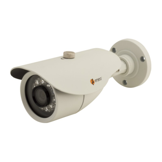
- Page 1 Full Manual 1/3" Camera, Day&Night, 900TVL, Infrared, 12VDC VKC-900IR36 VKC-900IR2812...
-
Page 2: Table Of Contents
Notes on safety ....................2 Overview ......................2 Introduction ..........................2 Functions and Features ......................2 Hardware Connection ..................3 Power and Video Cables ......................3 Function Keys ..........................3 Device Dimensions ....................5 Components and Functional Description ............6 Device Installation ....................7 Function Menus ....................9 OSD Main Menu ......................... -
Page 3: Notes On Safety
Notes on safety Please also pay attention to the enclosed safety instructions, and carefully read through this instruction guide before initial operation. Important points of advice are marked with a caution symbol. Overview Introduction The product is a 900 TVL infrared bullet camera that uses a SONY 1/3“Exmor CMOS image sensor which can capture high-quality and high-resolution images. -
Page 4: Hardware Connection
Hardware Connection Power and Video Cables Figure 2-1 shows the power and video cables. Power and video cables Figure 2-1 Connect the BNC connector of the power or video cable to a video signal cable and connect the other connector to a low-voltage power cable (12 V DC). After installing the camera, directly connect the video cable and power cable. - Page 5 UP/DOWN keys: The UP and DOWN keys are used to select menu items upwards and downwards by prodding the multi function switch upwards and downwards. LEFT/RIGHT keys: The LEFT and RIGHT keys are used to select menu items hori- zontally or modify parameters by prodding the multi function switch towards the left or the right.
-
Page 6: Device Dimensions
Device Dimensions Figure 3-1 shows the camera dimensions. Dimensions (unit: mm) Figure 3-1... -
Page 7: Components And Functional Description
Components and Functional Description Figure 4-1 shows the components of the camera. Camera components Figure 4-1... -
Page 8: Device Installation
Device Installation 1. Open a package, take out the camera, and unscrew the camera shell, as show in Figure 5-1. Unscrew the camera shell Figure 5-1 2. Take out the positioning label delivered with the camera and drill three holes with diameter of 5.5mm on the ceiling or wall based on the marks on the positi- oning label, nail swell plastic buttons into drilled holes, as shown in Figure 5-2. - Page 9 5. Adjust view angle and focal length by using an adjusting tool, as shown in Figure 5-4. View angle and focal length adjustment Figure 5-4 6. Fix the camera shell, as shown in Figure 5-5. Fix the camera shell Figure 5-5...
-
Page 10: Function Menus
Function Menus OSD Main Menu When you press the multi function switch control key downward, the OSD main menu MAIN MENU appears, as shown in Figure 6-1. The OSD main menu provides function options such as LANGUAGE, VIDEO SYSTEM, PICTURE ADJUST, AD- VANCE SETUP, RESET CAMERA, VERSION NO·, SAVE &EXIT, and EXIT. -
Page 11: Advanced Setup Menu
Image setting menu The table describes the function options on the image setting menu. Function options on the image setting menu Function Option Description Used to enable or disable the digital wide dynamic range function. Availab- D-WDR le options are ON and OFF. Used to select a white balance mode. - Page 12 The table describes the function options on the advanced setup menu. Function options on the advanced setup menu Function Option Description Used to select an exposure mode. Available options are SMART AE, GLO- BAL, CENTER, CENTER WEIG, BLACK LIGHT, FRONT LIGHT, and LOWER AE MODE 1/3.
-
Page 13: Technical Specifications
Technical Specifications The table lists the technical specifications of the camera. Technical specifications Description Specifications VKC-900IR36 VKC-900IR2812 Image sensor SONY 1/3“Exmor CMOS PAL: 1280(H)×960(V) Effective pixels NTSC: 1212(H)×909(V) Horizontal resolution 900 TVL Signal to noise ratio ≥50 dB (weighting) 0.01 Lux(AGC ON; IR OFF) - Page 14 Description Specifications VKC-900IR36 VKC-900IR2812 Power 1.2W(IR OFF)+2.9W (IR ON) 1.2W(IR OFF)+4W (IR ON) Operating temperature -10°C - +50°C Operating humidity Rh90% MAX (no condensation) Protection level IP66 Storage environment -30°C - +80°C Weight 350g 400g Dimensions(Length × Wide × Height) 194 mm×82mm×72 mm...
-
Page 15: Further Information
Further information The manual, and other software tools are available on the eneo website at www. eneo-security.com or on the included CD. - Page 16 VIDEOR E. Hartig GmbH Exclusive distribution through spe- cialised trade channels only. VIDEOR E. Hartig GmbH Carl-Zeiss-Straße 8 · 63322 Röder- mark/Germany Tel. +49 (0) 6074 / 888-0 · Fax +49 Technical changes reserved ©...
Need help?
Do you have a question about the VKC-900IR36 and is the answer not in the manual?
Questions and answers