Mitsubishi Electric PWFY-P100VM-E-BU Data Book
Hide thumbs
Also See for PWFY-P100VM-E-BU:
- Installation manual (184 pages) ,
- Operation manual (164 pages) ,
- Data book (78 pages)

Related Manuals for Mitsubishi Electric PWFY-P100VM-E-BU


Summary of Contents for Mitsubishi Electric PWFY-P100VM-E-BU
- Page 1 MODEL PWFY-P100VM-E-BU PWFY-EP100VM-E1-AU PWFY-EP100VM-E2-AU DATA BOOK 8th edition...
- Page 2 EG: Gloves, full arm protection namely boiler suit, It may also be in violation of applicable laws. and safety glasses. MITSUBISHI ELECTRIC CORPORATION cannot Improper handling may result in injury. be held responsible for malfunctions or accidents resulting from the use of the wrong type of • If refrigerant gas leaks during installation work,...
- Page 3 • If the air conditioner is installed in a small room, • Do not reconstruct or change the settings of the measures must be taken to prevent the refriger- protection devices. ant concentration from exceeding the safety limit If the pressure switch, thermal switch, or other even if the refrigerant should leak. protection device is shorted and operated forcibly, Consult the dealer regarding the appropriate meas- or parts other than those specified by Mitsubishi ures to prevent the safety limit from being exceeded. Electric are used, fire or explosion may result.
- Page 4 • Do not install the unit where combustible gas may • When installing the unit in a hospital, communica- leak. tion station, or similar place, provide sufficient protection against noise. If the gas leaks and accumulates around the unit, an explosion may result. The inverter equipment, private power generator, high-frequency medical equipment, or radio commu- • Do not use the air conditioner where food, pets, nication equipment may cause the air conditioner to plants, precision instruments, or artwork are kept.
- Page 5 • Ground the unit. • Do not wash the air conditioner units. Do not connect the ground wire to gas or water Washing them may cause an electric shock. pipes, lightning rods, or telephone ground lines. • Be careful that the installation base is not Improper grounding may result in electric shock. damaged by long use. • Install the power cable so that tension is not If the damage is left uncorrected, the unit may fall applied to the cable.
- Page 6 • Turn on the power at least 12 hours before • Do not turn off the power immediately after starting operation. stopping operation. Starting operation immediately after turning on the Always wait at least five minutes before turning off main power switch can result in severe damage the power. Otherwise, water leakage and trouble to internal parts. Keep the power switch turned on may occur.
-
Page 7: Table Of Contents
Contents Safety Precautions 4. Refrigerant circuit diagrams and thermal sensors ···· (1) PWFY-P100VM-E-BU (2) PWFY-EP100VM-E1-AU I General Equipment (3) PWFY-EP100VM-E2-AU Descriptions (4) PAC-SV01PW-E 1. Unit configuration table ········································· IV Installation 2. Operable temperature range ································· 3. Connectable outdoor unit/heat source unit 1. How to calculate the necessary heating capacity ·... - Page 8 VI Controller 1. PAR-W21MAA specifications ······························ 2. Dip switch functions ············································ VII Maintenance Cycle 1. Routine maintenance checks ······························ 2. Parts Replacement Cycle ··································· VIII Product Data (additional information for chapter III.) 1. Outdoor unit capacity tables ································ (1) Correction by refrigerant piping length (2) Correction at frosting and defrosting...
-
Page 9: I General Equipment
General Equipment Descriptions 1. Unit configuration table PWFY-EP100VM-E1-AU Model PWFY-P100VM-E-BU PWFY-EP100VM-E2-AU Outdoor unit Y series, HP (ZUBADAN) series, (Heat source unit for WY, R2 series, WR2 series only WY series, R2, WR2 series WR2 series) BC controller: CMB-P104,105,106,108,1010,1013,1016V-G1 BC controller Main BC controller: CMB-P108,1010,1013,1016V-GA1 / CMB-P1016V-HA1... -
Page 10: Connectable Outdoor Unit/Heat Source Unit Capacity Range
3. Connectable outdoor unit/heat source unit capacity range <PWFY-P100VM-E-BU> PWFY with Only standard Only PWFY standard indoor units indoor units R2/WR2 series 50 to 100% 50 to 150% 50 to 150% *1 In case of WCB connection, the capacity range will be "50 to 130%". <PWFY-EP100VM-E1-AU, PWFY-EP100VM-E2-AU>... -
Page 11: Product Specifications
Product Specifications 1. Specifications (1) PWFY-P100VM-E-BU Model PWFY-P100VM-E-BU 1-phase 220-230-240V 50/60Hz Power source 12.5 Heating capacity 10,800 (Nominal ) kcal / h 42,700 BTU / h 2.48 Power input Current input 11.63 - 11.12 - 10.66 Temp. range of for outdoor unit -20~32°C (-4~90°F) R2-series... - Page 12 (2) PWFY-EP100VM-E1-AU Model PWFY-EP100VM-E1-AU 1-phase 220-230-240V 50/60Hz Power source Heating capacity 12.5 10,800 (Nominal) kcal / h 42,700 BTU / h Power input 0.015 0.068 - 0.065 - 0.063 Current input Temp. range of heating -20~32°C (-4~90°F) R2-series Outdoor temp. for outdoor unit -20~15.5°C (-4~60°F) Y-series -25~15.5°C (-13~60°F) HP (ZUBADAN) -series...
- Page 13 (3) PWFY-EP100VM-E2-AU Model PWFY-EP100VM-E2-AU 1-phase 220-230-240V 50/60Hz Power source 12.5 Heating capacity 10,800 (Nominal) kcal / h 42,700 BTU / h Power input 0.025 - 0.026 - 0.027 0.138 - 0.139 - 0.140 Current input -20~32°C (-4~90°F) R2-series Temp. range of heating Outdoor temp.
-
Page 14: Cmb-P104V-G1
(4) CMB-P104V-G1 *Other models of BC controllers are available. For unit information, refer to the Data Book. Model CMB-P104V-G1 Number of branch Power source 1-phase 220/230/240V 50Hz 60Hz Power input Cooling 0.067/0.076/0.085 0.054/0.061/0.067 (220/230/240) Heating 0.030/0.034/0.038 0.024/0.027/0.030 Current Cooling 0.31/0.34/0.36 0.25/0.27/0.28 (220/230/240) Heating... -
Page 15: External Dimensions
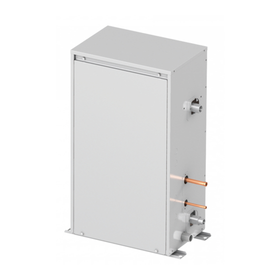
2. External Dimensions (1) PWFY-P100VM-E-BU - 7 -... - Page 16 (2) PWFY-EP100VM-E1-AU, PWFY-EP100VM-E2-AU - 8 -...
-
Page 17: Cmb-P104,105,106,108,1010,1013,1016V-G1
(3) CMB-P104,105,106,108,1010,1013,1016V-G1 *Other models of BC controller are available. For unit information, refer to the Data Book. - 9 -... - Page 18 (4) CMB-PW202V-J - 10 -...
-
Page 19: Electrical Wiring Diagrams
3. Electrical Wiring Diagrams (1) PWFY-P100VM-E-BU - 11 -... - Page 20 (2) PWFY-EP100VM-E1-AU - 12 -...
- Page 21 (3) PWFY-EP100VM-E2-AU - 13 -...
-
Page 22: Cmb-P104V-G1
(4) CMB-P104V-G1 *Other models of BC controller are available. For unit information, refer to the Data Book. - 14 -... - Page 23 (5) CMB-PW202V-J - 15 -...
-
Page 24: Accessories
(D) Wire (E) Flow switch (F) Buffer material *1. PWFY-P100VM-E-BU only *2. PWFY-EP100VM-E1/E2-AU only (A) Install the strainer at the water pipe inlet. (B) This insulation is for exclusive use with the strainer. Wrap the strainer with the insulation after water pipes are installed. -
Page 25: Optional Parts
5. Optional parts (1) Solenoid valve kit (For PWFY-EP100VM-E1-AU *1) PAC-SV01PW-E *1 PWFY-EP100VM-E2-AU do not need PAC-SV01PW-E because they are built in with the same functions. - 17 -... -
Page 26: Product Data
Product Data III 1. Capacity tables (1) Correction by temperature (Estimated performance without defrost) (1)-1 R2 series + PWFY-P100VM-E-BU PURY- P200,250YLM-A1(-BS) EP200,250YLM-A(-BS) Booster unit inlet-water temp. [°C] 40°C 50°C 60°C 65°C 30°C 20°C 10°C Outdoor temp. [°CWB] Booster unit inlet-water temp. [°C] 65°C 60°C... - Page 27 PURY- P300,350,400Y(S)LM-A1(-BS) EP300,350,400YLM-A(-BS) Booster unit inlet-water temp. [°C] 40°C 50°C 60°C 65°C 30°C 20°C 10°C Outdoor temp. [°CWB] Booster unit inlet-water temp. [°C] 65°C 60°C 50°C 40°C 30°C 20°C 10°C Outdoor temp. [°CWB] Booster unit inlet-water temp. [°C] 40°C 50°C 30°C 60°C 20°C...
- Page 28 PURY- P450,500,550,600,650Y(S)LM-A1(-BS) EP450,500,550,600,650YSLM-A(-BS) Booster unit inlet-water temp. [°C] 40°C 50°C 60°C 65°C 30°C 20°C 10°C Outdoor temp. [°CWB] Booster unit inlet-water temp. [°C] 65°C 60°C 50°C 40°C 30°C 20°C 10°C Outdoor temp. [°CWB] Booster unit inlet-water temp. [°C] 40°C 50°C 30°C 60°C 20°C...
- Page 29 PURY- P700,750,800,850,900YSLM-A1(-BS) EP700YSLM-A(-BS) Booster unit inlet-water temp. [°C] 40°C 50°C 60°C 65°C 30°C 20°C 10°C Outdoor temp. [°CWB] Booster unit inlet-water temp. [°C] 65°C 60°C 50°C 40°C 30°C 20°C 10°C Outdoor temp. [°CWB] Booster unit inlet-water temp. [°C] 40°C 50°C 30°C 60°C 20°C...
- Page 30 (1)-2 R2 series + PWFY-P100VM-E-BU + WCB Energy saving mode* *For energy saving mode, set WCB DIP SW 6-5 ON. PURY- P200,250YLM-A1(-BS) EP200,250YLM-A(-BS) Booster unit inlet-water temp. [°C] 40°C 50°C 60°C 30°C 65°C 20°C 10°C Outdoor temp. [°CWB] Booster unit inlet-water temp. [°C] 65°C...
- Page 31 PURY- P300,350YLM-A1(-BS) EP300,350YLM-A(-BS) Booster unit inlet-water temp. [°C] 40°C 50°C 60°C 30°C 65°C 20°C 10°C Outdoor temp. [°CWB] Booster unit inlet-water temp. [°C] 65°C 60°C 50°C 40°C 30°C 20°C 10°C Outdoor temp. [°CWB] Booster unit inlet-water temp. [°C] 30°C 40°C 50°C 20°C 10°C...
- Page 32 (1)-3 WR2 series + PWFY-P100VM-E-BU PQRY- P200,250,300,400,450,500,550,600Y(S)HM-A Booster unit inlet-water temp. [°C] 50°C 40°C 60°C 30°C 20°C 65°C 10°C Heat source unit (WR2) inlet-water temp. [°C] Booster unit inlet-water temp. [°C] 65°C 60°C 50°C 40°C 30°C 20°C 10°C Heat source unit (WR2) inlet-water temp. [°C] Booster unit inlet-water temp.
- Page 33 (1)-4 WR2 series + PWFY-P100VM-E-BU + WCB Energy saving mode* *For energy saving mode, set WCB DIP SW 6-5 ON. PQRY- P200,250,300,400,450,500,550,600Y(S)HM-A Booster unit inlet-water temp. [°C] 50°C 40°C 60°C 30°C 20°C 65°C 10°C Heat source unit (WR2) inlet-water temp. [°C] Booster unit inlet-water temp.
- Page 34 (1)-5 Y series + PWFY-EP100VM-E1-AU, PWFY-EP100VM-E2-AU PUHY- P-Y(S)KB-A1(-BS) Heating HEX unit inlet-water temp. [°C] 10°C 20°C 30°C 35°C 40°C Outdoor temp. [°CWB] HEX unit inlet-water temp. [°C] 40°C 35°C 30°C 20°C 10°C Outdoor temp. [°CWB] * The dashed lines show the reference values obtained from using the simulation. Cooling HEX unit inlet-water temp.
- Page 35 PUHY- EP-Y(S)LM-A(-BS) Heating HEX unit inlet-water temp. [°C] 10°C 20°C 30°C 35°C 40°C Outdoor temp. [°CWB] HEX unit inlet-water temp. [°C] 40°C 35°C 30°C 20°C 10°C Outdoor temp. [°CWB] * The dashed lines show the reference values obtained from using the simulation. Cooling HEX unit inlet-water temp.
- Page 36 (1)-6 HP (ZUBADAN) series + PWFY-EP100VM-E1-AU, PWFY-EP100VM-E2-AU PUHY- HP200,250,400,500Y(S)HM-A(-BS) Heating HEX unit inlet-water temp. [°C] 10°C 20°C 30°C 40°C Outdoor temp. [°CWB] HEX unit inlet-water temp. [°C] 30°C 20°C 10°C 40°C Outdoor temp. [°CWB] Cooling HEX unit inlet-water temp. [°C] 35°C 30°C 25°C...
- Page 37 (1)-7 R2 series + PWFY-EP100VM-E1-AU, PWFY-EP100VM-E2-AU PURY- P-Y(S)LM-A1(-BS) Heating HEX unit inlet-water temp. [°C] 10°C 20°C 30°C 35°C 40°C Outdoor temp. [°CWB] HEX unit inlet-water temp. [°C] 40°C 35°C 30°C 20°C 10°C Outdoor temp. [°CWB] * The dashed lines show the reference values obtained from using the simulation. Cooling HEX unit inlet-water temp.
- Page 38 PURY- EP-Y(S)LM-A(-BS) Heating HEX unit inlet-water temp. [°C] 10°C 20°C 30°C 35°C 40°C Outdoor temp. [°CWB] HEX unit inlet-water temp. [°C] 40°C 35°C 30°C 20°C 10°C Outdoor temp. [°CWB] * The dashed lines show the reference values obtained from using the simulation. Cooling HEX unit inlet-water temp.
- Page 39 (1)-8 WY series + PWFY-EP100VM-E1-AU, PWFY-EP100VM-E2-AU PQHY- P200,250,300,400,450,500,550,600,650,700,750,800,850,900Y(S)HM-A Heating HEX unit inlet-water temp. [°C] 10°C, 20°C, 30°C 40°C Heat source unit (WY) inlet-water temp. [°C] HEX unit inlet-water temp. [°C] 40°C 30°C 20°C 10°C Heat source unit (WY) inlet-water temp. [°C] Cooling HEX unit inlet-water temp.
- Page 40 (1)-9 WR2 series + PWFY-EP100VM-E1-AU, PWFY-EP100VM-E2-AU PQRY- P200,250,300,400,450,500,550,600Y(S)HM-A Heating HEX unit inlet-water temp. [°C] 10°C, 20°C, 30°C 40°C Heat source unit (WR2) inlet-water temp. [°C] HEX unit inlet-water temp. [°C] 40°C 30°C 20°C 10°C Heat source unit (WR2) inlet-water temp. [°C] Cooling HEX unit inlet-water temp.
- Page 41 (2) Correction by water flow rate (2) Correction by water flow rate (2)-1 PWFY-P100VM-E-BU <PWFY-P100VM-E-BU> 1.20 1.20 1.15 1.15 1.10 1.10 1.05 1.05 1.00 1.00 0.95 0.95 0.90 0.90 0.85 0.85 0.80 0.80 Booster unit water-volume [m Booster unit water-volume [m 1.20...
- Page 42 (4) Correction by refrigerant piping length Refer to Chapter VIII. (5) Correction at frosting and defrosting Refer to Chapter VIII. (6) Water pressure drop (6)-1 PWFY-P100VM-E-BU (with strainer) PWFY-P100VM-E-BU (with strainer) Water pressure drop of strainer Booster unit inlet-water volume [m (6)-2 PWFY-EP100VM-E1-AU, PWFY-EP100VM-E2-AU(with strainer)
- Page 43 (6)-3 Water pressure drop of Strainer only (accessory for PWFY-P100VM-E-BU and PWFY-EP100VM-E1,E2-AU) Booster/HEX unit inlet-water volume [m (7) Temperature range of running (7) Operation temperature range <PWFY-P100VM-E-BU> (7)-1 PWFY-P100VM-E-BU Heating PURY-(E)P . Y(S)LM-A(1)(-BS) (7) Temperature range of running <PWFY-P100VM-E-BU> Outdoor temp. [°CWB] Heating PQRY-P .
- Page 44 (7)-2 PWFY-EP100VM-E1-AU, PWFY-EP100VM-E2-AU PUHY-P . Y(S)KB-A1(-BS) Heating PUHY-EP . Y(S)LM-A(-BS) Outdoor temp. [°CWB] Heating PQHY-P . Y(S)HM-A Heat source unit circulating water temp. [°C] Heating PURY-(E)P . Y(S)LM-A(1)(-BS) Outdoor temp. [°CWB] Heating PQRY-P . Y(S)HM-A Heat source unit circulating water temp. [°C] - 36 -...
- Page 45 PUHY-P . Y(S)KB-A1(-BS) PUHY-EP . Y(S)LM-A(-BS) PURY-(E)P . Y(S)LM-A(1)(-BS) Cooling Outdoor temp. [°CDB] PQHY-P . Y(S)HM-A PQRY-P . Y(S)HM-A Cooling Heat source unit circulating water temp. [°C] Heating PUHY-HP . Y(S)HM-A Outdoor temp. [°CWB] PUHY-HP . Y(S)HM-A Cooling Outdoor temp. [°CDB] - 37 -...
-
Page 46: Sound Pressure Levels
2. Sound pressure levels (1) PWFY-P100VM-E-BU Measurement condition Sound level of PWFY-P100VM-E-BU PWFY-P100VM-E-BU NC-70 NC-60 Measurement NC-50 location NC-40 NC-30 Approximate minimum audible limit on NC-20 continuous noise Octave band center frequency <Hz> 500k dB(A) 50/60Hz 41.0 53.5 37.0 42.0 39.0 32.0 27.5 27.0... -
Page 47: Vibration Levels
VIBRATION LEVELS 3. Vibration levels PWFY-P100VM-E-BU (1) PWFY-P100VM-E-BU Service panel Measurement location Concrete 20cm 10cm Model Vibration Levels[dBA] PWFY-P100VM-E-BU - 39 -... -
Page 48: Refrigerant Circuit Diagrams And Thermal Sensors
4. Refrigerant circuit diagrams and thermal sensors Refrigerant Circuit Diagrams And Termal Sensors (1) PWFY-P100VM-E-BU LEV1W LEV2W TH22 Liquid Water inlet piping Brazed screw 63HS 63LS TH11 Water outlet piping screw Brazed PHEX TH13 63H1 COMP (2) PWFY-EP100VM-E1-AU PWFY-P100VM-E-BU Refrigerant circuit Water circuit Joint EJ (Size: R3/4 -> R1) - Page 49 (4) PAC-SV01PW-E Brazed Brazed Outdoor unit side PWFY side Brazed Brazed - 41 -...
-
Page 50: How To Calculate The Necessary Heating Capacity
Installation 1. How to calculate the necessary heating capacity (1) Heating capacity calculation A. For Air conditioning using such as Panel Heaters, Floor Heating and Fan coil units Required total heating capacity Safety factor; PWFY unit Tank B. For Sanitary use such as Shower and Bathrooms Conditions Tank inlet water Temp.;... -
Page 51: Installation
2. Installation (1) Selecting an installation site • Do not install outdoors. The unit is not waterproof. • Back up system is recommended in case of PWFY unit breakdown. • The unit will get hot. Do not install in a location where heat gets trapped inside. • Be sure to install unit in a place strong enough to withstand its weight. Any lack of strength may cause unit to fall down, resulting in a personal injury. • Do not install the unit where corrosive gas is generated. • Have installation work in order to protect against earthquake. Any installation deficiency may cause unit to fall down, resulting in a personal injury. • Pay a special attention to the place, such as a basement, etc. where refrigeration gas can stay, since refrigera- tion is heavier than the air. • Do not install the unit where combustible gas may leak. If the gas leaks and accumulates around the unit, an explosion may result. • When installing the unit in a hospital, communication station, or similar place, provide sufficient protection against noise. - Page 52 Tear plastic packaging bag and scrap it so that children cannot play with it. Otherwise plastic packaging bag may suffocate children to death. (2)-2 Product net weight Model PWFY-P100VM-E-BU Net weight 59 kg Model PWFY-EP100VM-E2-AU PWFY-EP100VM-E1-AU Net weight 36 kg 33 kg (2)-3 Center of gravity (2)-3-1 PWFY-P100VM-E-BU Unit : mm Model PWFY-P100VM-E-BU - 44 -...
- Page 53 (2)-3-2 PWFY-EP100VM-E1/E2-AU Unit : mm Model PWFY-EP100VM-E1-AU PWFY-EP100VM-E2-AU (2)-4 Installation method • Using the anchoring holes shown below, firmly bolt the unit to the base. [Fig. IV. 2. (2). 1] •PWFY unit •Solenoid valve kit Unit : mm Unit : mm (A) 4-ø14 (Anchoring hole) (A) 4-ø14 (Anchoring hole) (B) (Top view)
- Page 54 Be also sure to wind commercially available insulating material (with a form polyethylene’s specific gravity of 0.03 and thickness given below) onto all pipes which pass through rooms. Select the thickness of insulating material by pipe size. Unit : mm Model PWFY-P100VM-E-BU PWFY-EP100VM-E1-AU PAC-SV01PW-E PWFY-EP100VM-E2-AU Depends on the pipe ø15.88...
- Page 55 (4) Connecting refrigerant pipes and drain pipes (4)-1 Refrigerant piping work This piping work must be done in accordance with the installation manuals for both outdoor unit and BC controller/WCB (simultaneous cooling and heating R2 series). • R2 series is designed to operate in a system that the refrigerant pipe from an outdoor unit is received by BC controller/WCB and branches at the BC controller/WCB to connect between indoor units.
- Page 56 Cautions On Refrigerant Piping • Be sure to use non-oxidative brazing for brazing to ensure that no foreign matter or moisture enter into the pipe. • e sure to apply refrigerating machine oil over the flare connection seating surface and tighten the connection using a double spanner. • Provide a metal brace to support the refrigerant pipe so that no load is imparted to the indoor unit end pipe. This metal brace should be provided 500 mm away from the indoor unit’s flare connection. Warning: When installing and moving the unit, do not charge it with refrigerant other than the refrigerant (R407C or R22) specified on the unit. Mixing of a different refrigerant, air, etc. may cause the refrigerant cycle to malfunction and result in severe damage. Caution: • Use refrigerant piping made of C1220 (CU-DHP) phosphorus deoxidized copper as specified in the JIS H3300 “Copper and copper alloy seamless pipes and tubes”. In addition, be sure that the inner and outer surfaces of the pipes are clean and free of hazardous sulphur, oxides, dust/dirt, shaving particles, oils, moisture, or any other contaminant. • Never use existing refrigerant piping. The large amount of chlorine in conventional refrigerant and refrigerator oil in the existing piping will cause the new refrigerant to deteriorate.
-
Page 57: Water Pipe Installation
3. Water pipe installation (1) Water circuit sample Solid arrows in the figure indicate the direction of water flow. Roof Overflowed water City water To drain outlet PWFY Field supply Uphill gradient ≥ 1/200 Water-side Tank heat exchanger Tank Outlet Inlet Sample of water circuit for PWFY Consider the following when designing and installing a water piping system. - Page 58 When the ambient temperature is 0 ˚C or lower during stop operation, keep the water circulating at all times, or purge the water out of the pipes completely. Model Water inlet Water outlet PWFY-P100VM-E-BU PT 3/4 Screw PT 3/4 Screw PWFY-EP100VM-E1-AU PWFY-EP100VM-E2-AU...
- Page 59 (5) Example of unit installation [Fig. IV. 3.(5).1] (A) Close valve (E) Y-type strainer (C) (G) (B) Water inlet (F) Drain pipe (C) Water outletav (G) Expansion joint (D) Refrigerant piping (6) Insulation installation The surface temperature of the water pipe would be very high, depending on the set temperature. Insulate the pipe to prevent burns.
- Page 60 <Installation procedures> 1) Remove the pipes attached to the flow switch. Note: The unit is shipped with the pipes loosely tightened. 2) Wrap seal tape around the threads at the end of the pipes, starting at the 1.5th or 2nd thread, and not over the openings.
- Page 61 If the water quality level has dropped, please adjust water quality sufficiently before replacing the unit. Refer to the below graph for the maximum amount of circulating water in the water pipe. Make sure that this amount does not exceed. [Fig. IV. 3. (8).1] Maximum circulating water PWFY-P100VM-E-BU PWFY-EP100VM-E1/E2-AU 3000 2500...
- Page 62 (9) Brine When (a) PWFY-AU is used for cooling purpose, or (b) PWFY-AU is installed in the temperature condition below freezing temperature, Brine is required to add. Set Dip SW 1-10 (on ATW unit) to ON if brine is added. Brine concentration [wt%] ethylene glycol propylene glycol...
- Page 63 The unit may become damaged if it is operated with no water circulating through the pipes. Be sure to interlock unit operation and the water-circuit pump. In the system including PWFY-P100VM-E-BU, use the terminal blocks for interlocking TB142A (IN1) that can be found on the unit.
- Page 64 In a system that includes PWFY-EP100VM-E1-AU, if the operation of the pump is interlocked with the operation of the air conditioning units AND if the Solenoid valve kit (PAC-SV01PW-E) is connected to the system, connect the wires as shown in [Fig. IV.3.(10).3]. Set Dip SW3-6 to ON, and make sure that the version of the software is 1.18 or later. (PWFY-EP100VM-E2-AU do not need a solenoid valve kit because they are built in with the same functions.) [Fig.
-
Page 65: System Design
Volts Output (kW) Voltage range MCA (A) SC (A) Heating Max. 264 V 50/60 220-230-240 V 15.71 1.25 11.63-11.12-10.66 PWFY-P100VM-E-BU Min. 198 V Power supply RLA (A) Model Cooling Volts Voltage range Heating MCA (A) Max. 264 V 50/60 220-230-240 V 0.068-0.065-0.063... - Page 66 [Fig. V. 1.(2).1] (A) Breaker for current leakage PWFY-P100VM-E-BU PWFY-EP100VM-E1/E2-AU (B) Local switch or breakers for wiring (C) PWFY-P100VM-E-BU (D) PWFY-EP100VM-E1/E2-AU (E) Pull box (F) PAC-SV01PW-E (2)-3 When a solenoid valve kit is connected • Connect the solenoid valve kit TB2 and PWFY TB2.
- Page 67 (A) Outdoor unit M1M2 M1M2 M1M2 1 2 S (B) BC controller/WCB earth cable (shielded) (C) PWFY-P100VM-E-BU (D) PWFY-EP100VM-E1/E2-AU (E) MA remote controller (shielding wire) TB15 M1M2 • DC 10 to 13 V between 1 and 2 (MA remote controller) [Fig.
-
Page 68: Transmission Cables
(4) Transmission cable specifications (4)-1 Transmission cables PWFY-P100VM-E-BU Transmission cables MA Remote controller cables External input External output Shielding wire (2-core) Sheathed 2-core cable (shielded) Sheathed multi-core cable (shielded) Sheathed multi-core cable (unshielded) Type of cable CVVS, CPEVS or MVVS... - Page 69 • Fix power source external input/output line wiring to control box by using buffer bushing for tensile force to prevent electric shock. (PG connection or the like.) Connect transmission wiring to transmission terminal block through the knockout hole of control box using ordinary bushing. •...
- Page 70 (6) Indoor unit address setting (Be sure to operate with the main power turned OFF.) [Fig. V. 1.(6).1] <Address board> SWU2 SWU3 SWU1 (6)-1 Switch operation (BC controller) • There are two types of rotary switch setting available: setting addresses 1 to 9 and over 10, and setting branch numbers.
- Page 71 (6)-3 Rule of setting address Unit Address setting Example Note Use the most recent address within the same group of indoor units. Make the indoor units address connected to the BC controller (Sub) larger than the indoor units address connected to the BC controller (Main). If applicable, set the sub BC controllers in an PURY PWFY unit 01 ~ 50...
- Page 72 *1 For Wireless R/C and Signal receiver unit (SRU), channel 1, 2 and 3 are selectable and should be set to same channel. *2 System controller should connect to TB7 at Outdoor and use power supply unit together in Multi-Refrigerant-System. *3 Do not group PWFY-P100VM-E-BU and PWFY-EP100VM-E1/E2-AU together in the same group. NOTE: 1.
- Page 73 PWFY-EP100VM-E1/E2-AU with Y series outdoor units PUHY-P YKB/EP-YSLM PUHY-P-YKB/EP-YSLM PUHY-P-YKB/EP-YLM CN40 CN41 CN40 CN41 CN40 CN41 CN41 CN40 CN41 CN40 DipSW5-1 DipSW5-1 DipSW5-1 DipSW5-1 DipSW5-1 DipSW5-1 Group 2 PWFY-EP100VM-E1/E2-AU PWFY-EP100VM-E1/E2-AU PWFY-EP100VM-E1/E2-AU Indoor unit TB15 TB15 Transmission Booster PAC-SF46EPA (Main) Wireless R/C Group 32 PWFY-EP100VM-E1/E2-AU PWFY-EP100VM-E1/E2-AU LOSSNAY TB15 TB15...
- Page 74 (7) External input/output function [Fig. V. 1.(7).1] Preset temperature input (external analog input: 4mA-20mA) • External input Input through CN421, CN422 on the circuit board. (Fig. V. 1.(7).1) • External analog input current current External Use the supplied connector. direction direction analog input If no temperature settings are made via the MA remote controller, the temperature changes with the current of generator.
- Page 75 10ºC~45ºC enabling the unit to maintain low water temperature to prevent water pipes from freezing. IN5IN6 IN7 IN8 COM+ PWFY-P100VM-E-BU only Note: When setting Heating ECO or Anti-freeze mode, reset all power supply of all units (outdoor/indoor units). Note: Dip S/W 1-1 OFF: Water Inlet Temp. Dip S/W 1-1 ON : Water Outlet Temp.
-
Page 76: Piping Design
2. Piping Design (1) BC controller piping design (1)-1 IF 16 ports or less are in use, I.e., if only one BC controller is in use with no sub BC controller PURY-P-YLM-A1 Note1. No Header usable on PURY system. Joint CMY-R160-J1 Liquid side Note2. - Page 77 (1)-2 IF 16 ports or less are in use, I.e., if only one BC controller is in use with no sub BC controller PURY-EP-YLM Note1. No Header usable on PURY system. Note2. Indoor unit sized P100-P250 should be connected to BC controller via Y shape joint CMY-R160-J1 ; Note3.
- Page 78 (1)-3 IF more than 16 ports are in use, or if there is more than one BC controller in use for one outdoor unit PURY-P-YLM-A1 Note1. No Header usable on PURY system. Note2. Indoor unit sized P100-P250 should be connected to BC controller via Y shape joint CMY-R160-J1 ; Note3.
- Page 79 (1)-4 IF more than 16 ports are in use, or if there is more than one BC controller in use for one outdoor unit PURY-EP-YLM Note1. No Header usable on PURY system. Note2. Indoor unit sized P100-P250 should be connected to BC controller via Y shape joint CMY-R160-J1 ; Joint CMY-R160-J1 Liquid side Note3.
- Page 80 (1)-5 IF more than 16 ports are in use, or if there is more than one BC controller in use for two outdoor units PURY-P-YSLM-A1 Note1. No Header usable on PURY system. Note2. Indoor unit sized P100-P250 should be connected to BC controller via Y shape joint CMY-R160-J1 ; Note3.
- Page 81 (1)-6 IF more than 16 ports are in use, or if there is more than one BC controller in use for two outdoor units PURY-EP-YSLM Note1. No Header usable on PURY system. Note2. Indoor unit sized P100-P250 should be connected to BC controller via Y shape joint CMY-R160-J1 ; Note3.
- Page 82 (1)-7 Total piping length restrictions [PURY-P200, 250YLM-A1] [PURY-P300, 350YLM-A1] 1000 1000 90 100 110 90 100 110 Distance between outdoor unit and BC controller(m) Distance between outdoor unit and BC controller(m) [PURY-P400, 450, 500, 550Y(S)LM-A1] [PURY-P600, 650YSLM-A1] 1000 1000 90 100 110 90 100 110 Distance between outdoor unit and BC controller(m) Distance between outdoor unit and BC controller(m)
- Page 83 [PURY-EP200, 250YLM-A] [PURY-EP300, 350, 400, 450, 500YLM-A] 1000 1000 90 100 110 90 100 110 Distance between outdoor unit and BC controller(m) Distance between outdoor unit and BC controller(m) [PURY-EP550YSLM-A] [PURY-EP600, 650YSLM-A] 1000 1000 90 100 110 90 100 110 Distance between outdoor unit and BC controller(m) Distance between outdoor unit and BC controller(m) [PURY-EP700, 750, 800, 850, 900YSLM-A]...
- Page 84 (2) WCB piping design Indoor/ (Line branch Header branch PWFY branch possible) PWFY branch Capped Line branch (Header branch possible) Item Piping in the figure Maximum length Total piping length A+B+C+D+E+a+b+c+d+e+f+g 165 m Farthest IU from OU A+C+D+E+g / A+B+c (Max.
- Page 85 (3) Solenoid valve kit piping design SV kit SV kit SV kit SV kit *Do not install the Solenoid valve kit on the square-arch-shaped piping as shown in the figure above. Piping length limitation Item Piping in the figure Max. length (m) Farthest AU from first joint Length between AU and SV kit Height between AU and IC (AU)
- Page 86 (4) Refrigerant charging calculation (R2 system) PURY-P-YLM-A1 Sample connection (with 3 BC controller and 6 indoor units) (PURY-P700YSLM-A1) (Main unit) (Sub unit) Outdoor Twinning kit 5 : P140 BC controller (Sub BC) Joint BC controller (Main BC) Reducer (P15-P50) BC controller (Sub BC) Joint (attached with BC controller) Joint kit...
- Page 87 • When the piping length from the outdoor unit to the farthest indoor unit is longer than 30.5 m (100 ft) Amount of High-pressure pipe High-pressure pipe High-pressure pipe High-pressure pipe Liquid pipe ø15.88 additional ø28.58 total length ø22.2 total length ø19.05 total length ø15.88 total length total length...
- Page 88 PURY-EP-YLM Sample connection (with 3 BC controller and 6 indoor units) (PURY-EP700YSLM-A) (Main unit) (Sub unit) Outdoor Twinning kit 5 : P140 BC controller (Sub BC) Joint BC controller (Main BC) Reducer (P15-P50) BC controller (Sub BC) Joint (attached with BC controller) Joint Kit 2 : P250 1 : P50...
- Page 89 • When the piping length from the outdoor unit to the farthest indoor unit is longer than 30.5 m (100 ft) Amount of High-pressure pipe High-pressure pipe High-pressure pipe High-pressure pipe Liquid pipe ø15.88 additional ø28.58 total length ø22.2 total length ø19.05 total length ø15.88 total length total length...
- Page 90 (5) Refrigerant charging calculation (PWFY-AU with R2 system) It is needed to add extra refrigerant if the system is under the following conditions. See the attachment for how to decide the amount of refrigerant to be added to each outdoor unit. The graph below shows an example.
- Page 91 PURY-P400 PURY-EP400 PURY-P450 PURY-EP450 Additional Additional Refrigerant Refrigerant OK Zone OK Zone 28 30 34 36 38 40 48 50 System refrigerant [kg] System refrigerant [kg] PURY-P500 PURY-EP500 PURY-P550 PURY-EP550 Additional Additional Refrigerant Additional Refrigerant OK Zone OK Zone System refrigerant [kg] System refrigerant [kg] PURY-P600 PURY-EP600 PURY-P650 PURY-EP650...
-
Page 92: Controller
Controller 1. PAR-W21MAA specifications FUNCTION Item Description Operations Display ON/OFF Runs and stops the operation of a group of units Switches between Hot Water / Heating / Heating ECO / Anti-freeze / Cooling Operation mode switching * Available operation modes vary depending on the unit to be connected. * Switching limit setting can be made via a remote controller. -
Page 93: Dip Switch Functions
2. Dip switch functions Function according to switch setting Switch Function Switch setting timing TH0 thermistor selection Water inlet thermistor TH6 Water outlet thermistor TH8 Before power on Auto recovery (to the status Operation after power recovery *1 Remains stopped Before power on before power failure) Operation after power recovery Depends on the SW1-3 setting... -
Page 94: Maintenance Cycle
Maintenance Cycle VII 1. Routine maintenance checks • Periodically and thoroughly check the circulating water circuit. (See table below.) • Consult a maintenance technician. 2. Parts Replacement Cycle Regular preventive maintenance and parts replacement help keep the unit running smoothly and minimize problems. The table below shows the maintenance schedule. Use the replacement timing in the table only as a guide. Some parts may need to be replaced sooner, depending on the usage. -
Page 95: Product Data (Additional Information For Chapter Iii.)
Product Data (additional information for chapter III.) VIII 1. Outdoor unit capacity tables (1) Correction by refrigerant piping length (1)-1 Y series (PUHY-P-Y(S)KB-A1(-BS)) (1)-1-1 Cooling capacity correction PUHY-P400Y(S)KB-A1(-BS) PUHY-P200YKB-A1(-BS) Total capacity of indoor unit Total capacity of indoor unit 0.95 0.95 0.90 0.90 0.85 0.85 0.80 0.80 0.75 0.75 0.70 0.70 0.65 0.65... - Page 96 PUHY-P600YSKB-A1(-BS) PUHY-P800YSKB-A1(-BS) Total capacity of indoor unit Total capacity of indoor unit 0.95 0.95 0.90 0.90 0.85 0.85 0.80 0.80 0.75 0.75 0.70 0.70 1040 0.65 0.65 Piping equivalent length (m) Piping equivalent length (m) PUHY-P650YSKB-A1(-BS) PUHY-P850YSKB-A1(-BS) Total capacity of indoor unit Total capacity of indoor unit 0.95 0.95...
- Page 97 PUHY-P1000YSKB-A1(-BS) PUHY-P1200YSKB-A1(-BS) Total capacity of indoor unit Total capacity of indoor unit 0.95 0.95 0.90 0.90 0.85 0.85 0.80 0.80 1000 0.75 0.75 1200 1300 0.70 0.70 1560 0.65 0.65 Piping equivalent length (m) Piping equivalent length (m) PUHY-P1050YSKB-A1(-BS) PUHY-P1250YSKB-A1(-BS) Total capacity of indoor unit Total capacity of indoor unit 0.95...
- Page 98 (1)-1-2 Heating capacity correction PUHY-P200, 250YKB-A1(-BS) PUHY-P700, 750, 800YSKB-A1(-BS) 1.00 1.00 0.95 0.95 0.90 0.90 Piping equivalent length (m) Piping equivalent length (m) PUHY-P300, 350, 400, 450Y(S)KB-A1(-BS) PUHY-P850, 900, 950, 1000YSKB-A1(-BS) 1.00 1.00 0.95 0.95 0.90 0.90 Piping equivalent length (m) Piping equivalent length (m) PUHY-P500, 550, 600, 650Y(S)KB-A1(-BS) PUHY-P1050,1100,1150,1200,1250,1300,1350YSKB-A1(-BS)
- Page 99 (1)-2 Y series (PUHY-EP-Y(S)LM-A(-BS)) (1)-2-1 Cooling capacity correction PUHY-EP400YLM-A(-BS) PUHY-EP200YLM-A(-BS) Total capacity of indoor unit Total capacity of indoor unit 0.95 0.95 0.90 0.90 0.85 0.85 0.80 0.80 0.75 0.75 0.70 0.70 0.65 0.65 Piping equivalent length (m) Piping equivalent length (m) PUHY-EP250YLM-A(-BS) PUHY-EP450YLM-A(-BS) Total capacity of indoor unit...
- Page 100 PUHY-EP600YSLM-A(-BS) PUHY-EP800YSLM-A(-BS) Total capacity of indoor unit Total capacity of indoor unit 0.95 0.95 0.90 0.90 0.85 0.85 0.80 0.80 0.75 0.75 0.70 0.70 1040 0.65 0.65 Piping equivalent length (m) Piping equivalent length (m) PUHY-EP650YSLM-A(-BS) PUHY-EP850YSLM-A(-BS) Total capacity of indoor unit Total capacity of indoor unit 0.95 0.95...
- Page 101 PUHY-EP1000YSLM-A(-BS) PUHY-EP1200YSLM-A(-BS) Total capacity of indoor unit Total capacity of indoor unit 0.95 0.95 0.90 0.90 0.85 0.85 0.80 0.80 1000 0.75 0.75 1200 1300 0.70 0.70 1560 0.65 0.65 Piping equivalent length (m) Piping equivalent length (m) PUHY-EP1050YSLM-A(-BS) PUHY-EP1250YSLM-A(-BS) Total capacity of indoor unit Total capacity of indoor unit 0.95...
- Page 102 (1)-2-2 Heating capacity correction PUHY-EP200, 250YLM-A(-BS) PUHY-EP700, 750, 800YSLM-A(-BS) 1.00 1.00 0.95 0.95 0.90 0.90 Piping equivalent length (m) Piping equivalent length (m) PUHY-EP300, 350, 400, 450YLM-A(-BS) PUHY-EP850, 900, 950, 1000YSLM-A(-BS) 1.00 1.00 0.95 0.95 0.90 0.90 Piping equivalent length (m) Piping equivalent length (m) PUHY-EP500, 550, 600, 650Y(S)LM-A(-BS) PUHY-EP1050,1100,1150,1200,1250,1300,1350YSLM-A(-BS)
- Page 103 (1)-3 HP (ZUBADAN) series (1)-3-1 Cooling capacity correction PUHY-HP200YHM-A PUHY-HP400YSHM-A Total capacity of indoor unit Total capacity of indoor unit 0.95 0.95 0.90 0.90 0.85 0.85 0.80 0.80 0.75 0.75 0.70 0.70 0.65 0.65 Piping equivalent length (m) Piping equivalent length (m) PUHY-HP250YHM-A PUHY-HP500YSHM-A Total capacity of indoor unit...
- Page 104 (1)-4 R2 series (PURY-P-Y(S)LM-A1(-BS)) (1)-4-1 Cooling capacity correction PURY-P400Y(S)LM-A1(-BS) PURY-P200YLM-A1(-BS) Total capacity of indoor unit Total capacity of indoor unit 0.95 0.95 0.90 0.90 0.85 0.85 0.80 0.80 0.75 0.75 0.70 0.70 0.65 0.65 Piping equivalent length (m) Piping equivalent length (m) PURY-P250YLM-A1(-BS) PURY-P450Y(S)LM-A1(-BS) Total capacity of indoor unit...
- Page 105 PURY-P600YSLM-A1(-BS) PURY-P800YSLM-A1(-BS) Total capacity of indoor unit Total capacity of indoor unit 0.95 0.95 0.90 0.90 0.85 0.85 0.80 0.80 0.75 0.75 0.70 0.70 1200 0.65 0.65 Piping equivalent length (m) Piping equivalent length (m) PURY-P650YSLM-A1(-BS) PURY-P850YSLM-A1(-BS) Total capacity of indoor unit Total capacity of indoor unit 0.95 0.95...
- Page 106 (1)-4-2 Heating capacity correction PURY-P200YLM-A1(-BS) PURY-P550, 600, 650, 700, 750, 800, 850, 900YSLM-A1(-BS) 1.00 1.00 0.90 0.90 0.80 0.80 Piping equivalent length (m) Piping equivalent length (m) PURY-P250, 300YLM-A1(-BS) 1.00 0.90 0.80 Piping equivalent length (m) PURY-P350YLM-A1(-BS) 1.00 0.90 0.80 Piping equivalent length (m) PURY-P400, 450, 500Y(S)LM-A1(-BS) 1.00...
- Page 107 (1)-4-3 How to obtain the equivalent piping length 1 PURY-P200YLM-A1(-BS) Equivalent length = (Actual piping length to the farthest indoor unit) + (0.35 x number of bends in the piping) m 2 PURY-P250, 300YLM-A1(-BS) Equivalent length = (Actual piping length to the farthest indoor unit) + (0.42 x number of bends in the piping) m 3 PURY-P350YLM-A1(-BS) Equivalent length = (Actual piping length to the farthest indoor unit) + (0.47 x number of bends in the piping) m 4 PURY-P400, 450, 500, 550, 600, 650Y(S)LM-A1(-BS)
- Page 108 (1)-5 R2 series (PURY-EP-Y(S)LM-A(-BS)) (1)-5-1 Cooling capacity correction PURY-EP400YLM-A(-BS) PURY-EP200YLM-A(-BS) Total capacity of indoor unit Total capacity of indoor unit 0.95 0.95 0.90 0.90 0.85 0.85 0.80 0.80 0.75 0.75 0.70 0.70 0.65 0.65 Piping equivalent length (m) Piping equivalent length (m) PURY-EP250YLM-A(-BS) PURY-EP450YLM-A(-BS) Total capacity of indoor unit...
- Page 109 PURY-EP600YSLM-A(-BS) PURY-EP800YSLM-A(-BS) Total capacity of indoor unit Total capacity of indoor unit 0.95 0.95 0.90 0.90 0.85 0.85 0.80 0.80 0.75 0.75 0.70 0.70 1200 0.65 0.65 Piping equivalent length (m) Piping equivalent length (m) PURY-EP650YSLM-A(-BS) PURY-EP850YSLM-A(-BS) Total capacity of indoor unit Total capacity of indoor unit 0.95 0.95...
- Page 110 (1)-5-2 Heating capacity correction PURY-EP200YLM-A(-BS) PURY-EP550, 600, 650, 700, 750, 800, 850, 900YSLM-A(-BS) 1.00 1.00 0.90 0.90 0.80 0.80 Piping equivalent length (m) Piping equivalent length (m) PURY-EP250, 300YLM-A(-BS) 1.00 0.90 0.80 Piping equivalent length (m) PURY-EP350YLM-A(-BS) 1.00 0.90 0.80 Piping equivalent length (m) PURY-EP400, 450, 500YLM-A(-BS) 1.00...
- Page 111 (1)-5-3 How to obtain the equivalent piping length 1 PURY-EP200YLM-A(-BS) Equivalent length = (Actual piping length to the farthest indoor unit) + (0.35 × number of bends in the piping) m 2 PURY-EP250, 300YLM-A(-BS) Equivalent length = (Actual piping length to the farthest indoor unit) + (0.42 × number of bends in the piping) m 3 PURY-EP350YLM-A(-BS) Equivalent length = (Actual piping length to the farthest indoor unit) + (0.47 ×...
- Page 112 (1)-6 WY series (1)-6-1 Cooling capacity correction PQHY-P450YSHM-A PQHY-P200YHM-A Total capacity of indoor unit Total capacity of indoor unit 1.00 1.00 0.95 0.95 0.90 0.90 0.85 0.85 0.80 0.80 0.75 0.75 0.70 0.70 0.65 0.65 Piping equivalent length (m) Piping equivalent length (m) PQHY-P250YHM-A PQHY-P500YSHM-A Total capacity of indoor unit...
- Page 113 PQHY-P650YSHM-A PQHY-P850YSHM-A Total capacity of indoor unit Total capacity of indoor unit 1.00 1.00 0.95 0.95 0.90 0.90 0.85 0.85 0.80 0.80 0.75 0.75 1105 0.70 0.70 0.65 0.65 Piping equivalent length (m) Piping equivalent length (m) PQHY-P700YSHM-A PQHY-P900YSHM-A Total capacity of indoor unit Total capacity of indoor unit 1.00 1.00...
- Page 114 (1)-6-2 Heating capacity correction PQHY-P200YHM-A PQHY-P400, 450, 500YSHM-A 1.00 1.00 0.95 0.95 0.90 0.90 0.85 0.85 0.80 0.80 0.75 0.75 0.70 0.70 0.65 0.65 Piping equivalent length (m) Piping equivalent length (m) PQHY-P250, 300YHM-A PQHY-P550, 600YSHM-A 1.00 1.00 0.95 0.95 0.90 0.90 0.85...
- Page 115 (1)-6-3 How to obtain the equivalent piping length 1 PQHY-P200YHM Equivalent length = (Actual piping length to the farthest indoor unit) + (0.35 × number of bends in the piping) m 2 PQHY-P250, 300YHM Equivalent length = (Actual piping length to the farthest indoor unit) + (0.42 × number of bends in the piping) m 3 PQHY-P400, 450, 500, 550, 600, 650YSHM Equivalent length = (Actual piping length to the farthest indoor unit) + (0.50 ×...
- Page 116 (1)-7 WR2 series (1)-7-1 Cooling capacity correction PQRY-P450YSHM-A PQRY-P200YHM-A Total capacity of indoor unit Total capacity of indoor unit 1.00 1.00 0.95 0.95 0.90 0.90 0.85 0.85 0.80 0.80 0.75 0.75 0.70 0.70 0.65 0.65 Piping equivalent length (m) Piping equivalent length (m) PQRY-P250YHM-A PQRY-P500YSHM-A Total capacity of indoor unit...
- Page 117 (1)-7-2 Heating capacity correction PQRY-P200YHM-A PQRY-P400, 450, 500YSHM-A 1.00 1.00 0.95 0.95 0.90 0.90 0.85 0.85 0.80 0.80 0.75 0.75 0.70 0.70 0.65 0.65 Piping equivalent length (m) Piping equivalent length (m) PQRY-P250, 300YHM-A PQRY-P550, 600YSHM-A 1.00 1.00 0.95 0.95 0.90 0.90 0.85...
- Page 118 (2) Correction at frosting and defrosting Due to frosting at the outdoor heat exchanger and the automatical defrosting operation, the heating capacity of the outdoor unit should be considered by multiplying the correction factor which shown in the table below. (2)-1 Y series (PUHY-P-Y(S)KB-A1(-BS)) Table of correction factor at frost and defrost Outdoor inlet air temp.
- Page 119 (2)-2 Y series (PUHY-EP-Y(S)LM-A(-BS)) Table of correction factor at frost and defrost Outdoor inlet air temp. °C Outdoor inlet air temp. °F PUHY-EP200YLM-A(-BS) 1.00 0.95 0.84 0.825 0.83 0.87 0.90 0.95 0.95 0.95 0.95 PUHY-EP250YLM-A(-BS) 1.00 0.95 0.84 0.825 0.83 0.87 0.90 0.95...
- Page 120 (2)-4 R2 series (PURY-P-Y(S)LM-A1(-BS)) Table of correction factor at frost and defrost 0.95 0.95 PURY-P200YLM-A1(-BS) 1.00 0.95 0.84 0.83 0.83 0.87 0.90 0.95 0.95 0.95 PURY-P250YLM-A1(-BS) 1.00 0.95 0.84 0.83 0.83 0.87 0.90 0.95 0.95 0.95 PURY-P300YLM-A1(-BS) 1.00 0.93 0.82 0.80 0.82 0.86...
- Page 121 - Doing so may cause the unit or pipes to burst, or result in explosion or fire during use, during repair, or at the time of disposal of the unit. - It may also be in violation of applicable laws. - MITSUBISHI ELECTRIC CORPORATION cannot be held responsible for malfunctions or accidents resulting from the use of the wrong type of refrigerant. ■...
Need help?
Do you have a question about the PWFY-P100VM-E-BU and is the answer not in the manual?
Questions and answers