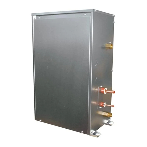
Mitsubishi Electric CITY MULTI PWFY-P100VM-E-BU Installation Manual
Air conditioning systems, indoor unit
Hide thumbs
Also See for CITY MULTI PWFY-P100VM-E-BU:
- Installation manual (184 pages) ,
- Operation manual (164 pages) ,
- Data book (121 pages)
Table of Contents
Advertisement
Quick Links
AIR CONDITIONING SYSTEMS
INDOOR UNIT
PWFY-P100VM-E-BU
PWFY-P100VM-E1-AU
PWFY-EP100VM-E1-AU
PWFY-P200VM-E1-AU
INSTALLATION MANUAL
For safe and correct use, please read this installation manual thoroughly before installing the indoor unit.
PWFY-P100VM-E2-AU
PWFY-EP100VM-E2-AU
PWFY-P200VM-E2-AU
<ORIGINAL>
Advertisement
Table of Contents

Summary of Contents for Mitsubishi Electric CITY MULTI PWFY-P100VM-E-BU
- Page 1 <ORIGINAL> AIR CONDITIONING SYSTEMS INDOOR UNIT PWFY-P100VM-E-BU PWFY-P100VM-E2-AU PWFY-P100VM-E1-AU PWFY-EP100VM-E2-AU PWFY-EP100VM-E1-AU PWFY-P200VM-E2-AU PWFY-P200VM-E1-AU INSTALLATION MANUAL For safe and correct use, please read this installation manual thoroughly before installing the indoor unit.
- Page 2 [Fig. 6.1.1] [Fig. 6.2.1] A Piping space (right side) B Top view A 4-ø14 (Anchoring hole) C Service space (front side) B (Top view) PWFY-P200VM-E1/E2-AU [Fig. 7.1.1] [Fig. 7.1.2] PWFY-EP100VM-E1/E2-AU A Close valve D Y-type strainer E Drain pipe B Water inlet F Expansion joint C Water outlet D Refrigerant piping...
- Page 3 [Fig. 7.1.3] Single system sample Note: The figure above shows a sample water circuit. This circuit is provided only as a reference, and Mitsubishi Electric Corporation shall not be held responsible for any problems arising from the use of this circuit. [Fig.
- Page 4 [Fig. 7.1.5] PWFY-P100VM-E-BU PWFY-(E)P100/200VM-E1/E2-AU 3000 2500 2000 1500 1000 A Water volume limitation [L] B Total hardness [mg/L] C Available water volume area [Fig. 7.2.1] [Fig. 7.4.1] [Fig. 7.4.2] Board AC208 - 230V TB142A DC30V or less TB141A OUT1 × ×...
- Page 5 [Fig. 8.1.1] A Refrigerant piping (gas) B Refrigerant piping (liquid) C Water inlet D Water outlet E Drain outlet *1: PWFY-(E)P100/200VM-E1/E2-AU 184 (206*1) [Fig. 9.1.1] [Fig. 9.1.2] A Cut here B Remove brazed cap A Thermal insulation B Pull out insulation C Wrap with damp cloth D Return to original position E Ensure that there is no gap here...
- Page 6 10.1 [Fig. 10.1.1] PWFY- P100VM-E-BU PWFY- (E)P100/200VM-E1/E2-AU A Breaker for current leakage B Local switch or breakers for wiring C PWFY-P100VM-E-BU D PWFY-(E)P100/200VM-E1/E2-AU E Pull box 10.2 [Fig. 10.2.1] TB02 TB15 M1M2 M1M2 M1M2 1 2 S earth cable (shielded) (shielding wire) A Outdoor unit TB15...
-
Page 7: Table Of Contents
- If the pressure switch, thermal switch, or other protection device is shorted and • Do not use steel pipes as water pipes. operated forcibly, or parts other than those specified by Mitsubishi Electric are - Copper pipes are recommended. -
Page 8: Precautions For Devices That Use R410A Refrigerant
- It may also be in violation of applicable laws. - Tension may cause the cable to break and generate heat and cause a fire. - MITSUBISHI ELECTRIC CORPORATION cannot be held responsible for mal- • Install a leak circuit breaker, as required. -
Page 9: About The Product
- Doing so may cause the unit or pipes to burst, or result in explosion or fire during use, during repair, or at the time of disposal of the unit. - It may also be in violation of applicable laws. - MITSUBISHI ELECTRIC CORPORATION cannot be held responsible for malfunctions or accidents resulting from the use of the wrong type of refrigerant. Model... -
Page 10: Water Pipe Installation
The figure above shows a sample water circuit. This circuit is provided only as a PWFY-P100VM-E1/E2-AU PT 3/4 Screw PT 3/4 Screw reference, and Mitsubishi Electric Corporation shall not be held responsible for PWFY-EP100VM-E1/E2-AU PT 1 Screw*1 PT 1 Screw*1 any problems arising from the use of this circuit. -
Page 11: Water Processing And Water Quality Control
7.3. Water processing and water quality control To preserve water quality, use the closed type water circuit. When the circulating water quality is poor, the water heat exchanger can develop scales, leading to a reduction in heat-exchange power and possible corrosion of the heat exchanger. Please pay careful attention to water processing and water quality control when installing the water cir- culation system. -
Page 12: Refrigerant Pipe And Drain Pipe Specifications
Caution: - It may also be in violation of applicable laws. - MITSUBISHI ELECTRIC CORPORATION cannot be held responsible for mal- • Install the refrigerant piping for the indoor unit in accordance with the fol- lowing. -
Page 13: Connecting Electrical Connections
2. Ensure that any cross-wise drain piping is less than 20 m (excluding the difference Note: of elevation). If the drain piping is long, provide metal braces to prevent it from Ensure that the wiring is not pinched when fitting the terminal box cover. waving. -
Page 14: Connecting Remote Controller, Indoor And Outdoor Transmission Cables
Power supply RLA (A) Model Volts Voltage range MCA (A) Cooling Heating PWFY-P100VM-E1-AU Max. 264 V PWFY-EP100VM-E1-AU 50/60 220-230-240 V 0.085 0.068-0.065-0.063 Min. 198 V PWFY-P200VM-E1-AU PWFY-P100VM-E2-AU Max. 264 V PWFY-EP100VM-E2-AU 50/60 220-230-240 V 0.175 0.138-0.139-0.140 Min. 198 V PWFY-P200VM-E2-AU 2. -
Page 15: Setting Addresses
- Doing so may cause the unit or pipes to burst, or result in explosion or fire during use, during repair, or at the time of disposal of the unit. - It may also be in violation of applicable laws. - MITSUBISHI ELECTRIC CORPORATION cannot be held responsible for malfunctions or accidents resulting from the use of the wrong type of refrigerant. Model... - Page 16 Please be sure to put the contact address/telephone number on this manual before handing it to the customer. HEAD OFFICE: TOKYO BLDG., 2-7-3, MARUNOUCHI, CHIYODA-KU, TOKYO 100-8310, JAPAN Authorized representative in EU:MITSUBISHI ELECTRIC EUROPE B.V. HARMAN HOUSE, 1 GEORGE STREET, UXBRIDGE, MIDDLESEX UB8 1QQ, U.K. WT07390X01...


Need help?
Do you have a question about the CITY MULTI PWFY-P100VM-E-BU and is the answer not in the manual?
Questions and answers