
Subscribe to Our Youtube Channel
Related Manuals for Delta D3000


Summary of Contents for Delta D3000
- Page 1 User Manual DME-D302ABS A SERIES DC Power Supply D3000 DC Power Supply User Manual www.deltaww.com...
-
Page 2: Table Of Contents
User Manual D3000 DC Power Supply Guarantee ..............................Safety Instructions ..........................3 Accessories .............................4 Revision History ..........................4 Chapter1 General Information ......................5 1.1 User Manual Content ..........................5 1.2 Introduction ............................5 1.2.1 General description ........................5 1.2.2 Features and options........................5 1.2.3 Multiple output power system ....................... - Page 3 2.8 Connecting The Load .......................... 18 2.8.1 Load Wiring ..........................18 2.8.2 Current Carrying Capacity ......................18 2.8.3 Wire termination ......................... 19 2.8.4 Noise and Impedance Effects ....................20 2.8.5 Inductive loads ........................... 20 2.8.6 Connecting single loads, local sensing (default)................ 20 2.8.7 Connecting single loads, remote sensing ..................
- Page 4 3.2.3 Over Voltage Protection (OVP) ....................37 3.2.3.1 Setting the OVP level ......................37 3.2.3.2 Activated OVP protection indications ................... 37 3.2.3.3 Resetting the OVP circuit ..................... 37 3.2.4 Under Voltage Limit (UVL)......................38 3.2.4.1 Setting the UVL level ......................38 3.2.5 Foldback Protection........................
- Page 5 4.2.2.2 Address setting ........................55 4.2.2.3 RS232 or RS485 selection ....................56 4.2.2.4 Baud rate setting ........................56 4.2.2.5 Setting the unit into Remote or Local mode ................. 56 4.2.2.6 RS232/485 port in Local mode ..................... 56 4.2.3 Rear Panel RS232/485 Connector ..................... 57 4.2.4 Connecting Power Supplies To RS232 Or RS485 Bus ..............
-
Page 6: Guarantee
Guarantee THE SCOPE OF RIGHT: 1. Delta Electronics Co., Ltd. guarantees the quality of all sales of products in Taiwan, and is responsible for fault repair, to safeguard the interests of your company. 2. When encountered fault conditions in need of services, please contact the Taiwan presence or Delta Electronics. - Page 7 User Manual D3000 DC Power Supply To exceed the Warranty Period: (1) Use within the warranty period after the Company sent a free guide or instructions, still can not adjust, and the request for service (2) Ensure that the contents of the record book, and now the items are inconsistent.
-
Page 8: Safety Instructions
Do not use AC supply which exceeds the input voltage and frequency rating of this instrument. The input voltage and frequency rating of the D3000 is: 200-240V~, 50/60Hz.For safety reasons, the mains supply voltage fluctuations should not exceed +/-10% of nominal voltage. -
Page 9: Accessories
D3000 DC Power Supply PARTS SUBSTITUTIONS & MODIFICATIONS Parts substitutions and modifications are allowed by authorized Delta service personnel only. For repairs or modifications, the instrument must be returned to Delta service facility. ENVIRONMENTAL CONDITIONS The DME-D302ABS A safety approval applies to the following operating conditions: *Indoor use *Ambient temperature: 0℃... -
Page 10: Chapter1 General Information
Chapter1 General Information 1.1 User Manual Content This user's manual contains the operating instructions, installation instructions and specifications of the D3000 power supplies. The instructions refer to the standard power supplies, including the built-in RS232/485/IEEE serial communication. 1.2 Introduction 1.2.1 General description DME-D302ABS A high performance programmable DC power supplies. -
Page 11: Multiple Output Power System
DC Power Supply 1.2.3 Multiple output power system D3000 can be configured into a programmable power system of up to 31 units using the built-in RS232/RS485 communication port in the power supply and the RS485 linking cable provided with each power supply. -
Page 12: Cooling And Mechanical Construction
1.2.8 Cooling and mechanical construction D3000 is cooled by internal fans. At the installation, care must be taken to allow free air flow into the power supply via the front panel and out of the power supply via the rear panel. - Page 13 User Manual D3000 DC Power Supply Transient response time Time for the output voltage to recover within 0.5% of its rated output for a load change 10~90% of rated output current. Output set- point: 10~100%. Hold-up time 10ms Typical. Rated output power.
- Page 14 User Manual D3000 DC Power Supply Series operation Possible (with external diodes), up to 2 units. 600Vdc max. from chassis ground. CV/CC indicator Open collector. CV: Off CC: On, Maximum voltage: 30V sink current: 10mA. Enable/Disable Dry contact. Open: off, Short: on. Max.
- Page 15 User Manual D3000 DC Power Supply Go to local control. Output on/off AC on/off Front panel Lock Foldback control Baud rate selection: 1200, 2400, 4800, 9600 and 19200. Re-start modes (automatic restart, safe mode). Display Vout: 4 digits, accuracy: 0.5% of rated output voltage +/-1 count.
- Page 16 User Manual D3000 DC Power Supply Vibration TEST CONDITIONS: a. NON-OPERATING b. SINUSOIDAL c. ACCELERATION: 0.5G (5Hz), 0.94G (10~150Hz) d. Duration: 30 minutes for each three axis (X, Y, Z) Shock TEST CONDITIONS: a. NON-OPERATING b. HALF SINUSOIDAL c. NUMBER OF SHOCK: 6 SHOCKS FOR EACH DIRECTION.
-
Page 17: Supplemental Characteristics
3. EN61000 Data: Performance of the power supply under EN61000 test conditions. 4. EMI Data: Typical EMI (conducted and radiated) performance of the power supply. The supplemental characteristics data is held in each DELTA sales and service facility. For further details please contact the DELTA office nearest you. -
Page 18: Chapter2 Installation
Keep all packing material until the inspection has been completed. If damage is detected, file a claim with carrier immediately and notify the Delta sales or service facility nearest you. -
Page 19: Location, Mounting And Cooling
+50ºC. 2.5 AC Source Requirements The D3000 can be operated from a nominal 170V to 265V, single phase, 47~63Hz. The input voltage range and current required for each model is specified in Chapter 2. Ensure that under heavy load, the AC voltage supplied to the power supply does not fall below the specifications described in Section 1.3. -
Page 20: Turn-On Checkout Procedure
User Manual D3000 DC Power Supply 2.7 Turn-on Checkout Procedure 2.7.1 General The following procedure ensures that the power supply is operational and may be used as a basic incoming inspection check. Refer to Fig.3-1 and Fig.3-2 for the location of the controls indicated in the procedure. -
Page 21: Ovp Check
User Manual D3000 DC Power Supply 3. Turn the front panel AC power switch to On position. 4. Turn on the output by pressing OUT pushbutton so the OUT LED illuminates. 5. Observe the power supply CURRENT display and rotate the CURRENT encoder. Ensure that the output current varies while the CURRENT encoder is rotated. -
Page 22: Foldback Check
User Manual D3000 DC Power Supply 2.7.7 Foldback Check WARNING Shorting the output may expose the user to hazardous voltages. Observe proper safety procedures. Refer to Section 3.2.5 for explanation of the FOLD function prior to performing the procedure below. -
Page 23: Connecting The Load
User Manual D3000 DC Power Supply 2.8 Connecting The Load WARNING Turn off the AC input power before making or changing any rear panel connection. Ensure that all connections are securely tightened before applying power. There is a potential shock hazard when using a power supply with a rated output greater than 40V. -
Page 24: Wire Termination
User Manual D3000 DC Power Supply Table 2-2: Maximum wire length for 1V drop on lead (in feet) Wire size Resistivity Maximum length in Feet to limit voltage Ohm/100 0ft drop to 1V or less 150A 2.526 1.589 0.9994 0.6285 0.3953... -
Page 25: Noise And Impedance Effects
User Manual D3000 DC Power Supply 2.8.4 Noise and Impedance Effects To minimize the noise pick up or radiation, the load wires and remote sense wires should be twisted-pairs to the shortest possible length. Shielding of sense leads may be necessary in high noise environments. -
Page 26: Connecting Single Loads, Remote Sensing
User Manual D3000 DC Power Supply 2.8.7 Connecting single loads, remote Fig.2-3 shows recommended remote sensing connection for single loads. Remote sensing is used when, in Constant Voltage mode, the load regulation is important at the load terminals. Use twisted or shielded wires to minimize noise pick-up. If shielded wires are used, the shield should be connected to the ground at one point, either at the power supply chassis or the load ground. -
Page 27: Multiple Load Connection With Distribution Terminals
User Manual D3000 DC Power Supply 2.8.9 Multiple load connection with distribution terminals If remotely located output distribution terminals are used, the power supply output terminals should be connected to the distribution terminals by a pair of twisted and/or shielded wires. -
Page 28: Local And Remote Sensing
User Manual D3000 DC Power Supply 2.9 Local And Remote Sensing The rear panel J2 sense connector is used to configure the power supply for local or remote sensing of the output voltage. Refer to Fig.2-6 for sense connector location. -
Page 29: Remote Sensing
User Manual D3000 DC Power Supply Table 2-4: J2 terminals Terminal Function J2-1 Remote positive sense (+S). J2-2 Local positive sense. Connected internally to the positive output terminal (+LS). J2-3 Not connected (NC). J2-4 Local negative sense. Connected internally to the negative output terminal (-LS). -
Page 30: J2 Sense Connect Or Technical Information
-Tightening torque: 1.95-2.21Lb-Inch. (0.22-0.25Nm) 2.10 Repackaging For Shipment To ensure safe transportation of the instrument, contact the DELTA sales or service facility near you for Return Authorization and shipping information. Please attach a tag to the power supply describing the problem and specifying the owner, model number and serial number of the power supply. -
Page 31: Chapter 3 Local Operation
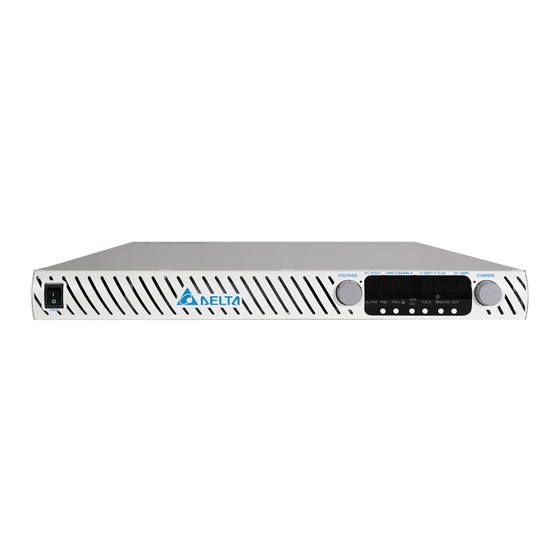
3.1 Front And Rear Panel Controls And Connectors 3.1.1 Introduction The D3000 has a full set of controls, indicators and connectors that allow the user to easily setup and operate the unit. Before starting to operate the unit, please read the following sections for explanation of the functions of the controls and connectors terminals. - Page 32 User Manual D3000 DC Power Supply CURRENT display 4 digit, 7-segment LED display. Normally displays the output current. When the PREV button is pressed, the display indicates the programmed setting of output current. CURRENT indicator Green LED, lights for Constant-Current mode operation.
-
Page 33: Front Panel Locking
User Manual D3000 DC Power Supply PREV/ button Main function: Press PREV to display the output 3.1.3 voltage and current limit setting. For 5 sec. the display will show the setting and then it will return to show the actual output voltage and current. -
Page 34: Locked Front Panel
User Manual D3000 DC Power Supply 3.1.3.2 Locked front panel In this mode the following front panel controls are disabled: -VOLTAGE and CURRENT encoders. -FOLD button. -OUT button. The power supply will not respond to attempts to use these controls. The VOLT display will show “LFP”... -
Page 35: Auxiliary Power Supply
User Manual D3000 DC Power Supply Remote Out RJ-45 type connector, used for chaining power 4.2.3 connector supplies to forma serial communication bus. 4.2.4 Programming Connector for remote analog interface. Includes output 3.1.7.1 and Monitoring voltage and current limit programming and monitoring... -
Page 36: Rear Panel Sw1 Setup Switch
User Manual D3000 DC Power Supply CAUTION Do not attempt to bias any of these terminals relative to the V- or any other potential. 3.1.6 Rear Panel Sw1 Setup Switch The SW1 Setup switch (see Fig.3-3) is a 9-position DIP switch that allows the user to choose the following: -Internal or remote programming for Output Voltage and Current Limit. -
Page 37: Resetting The Sw1 Switch
User Manual D3000 DC Power Supply SW1-3 Programming range select 0-5V / (0-5Kohm) 0-10V / (0-10Kohm) (Remote voltage/resistive) SW1-4 Output Voltage and 0-5V 0-10V Current Monitoring range SW1-5 Shut Off logic select On: Open On: Short Off: Short Off: Open... - Page 38 User Manual D3000 DC Power Supply CAUTION Terminals 12, 22 and 23 of J1 are connected internally to of the power supply. Do not attempt to bias any of these terminals relative to the negative sense. Use the Programming interface option to allow control from a programming source at a different...
- Page 39 User Manual D3000 DC Power Supply J1-10 IPGM Input for remote analog voltage/resistance Sec. 4.1.1~4.1.5 programming of the Output Current. J1-11 VMON Output for monitoring the power supply Output Sec. 4.1.6 Voltage. J1-12 Control Common. Return for VMON, IMON, CV/CC, LOC/REM.
-
Page 40: Local Operation
User Manual D3000 DC Power Supply 3.2 Local Operation 3.2.1 Introduction This Chapter describes the operating modes that are not involved in programming and monitoring the power supply via its serial communication port (RS-232/485) or by remote analog signals. Ensure that the REM/LOC LED on the front panel is Off, indicating Local mode. -
Page 41: Constant Current Operation
User Manual D3000 DC Power Supply NOTE If after completing the adjustment, the display shows a different value than the setting, the power supply may be at current limit. Check the load condition and the power supply current limit setting. -
Page 42: Automatic Crossover
User Manual D3000 DC Power Supply 3.2.2.3 Automatic Crossover If the power supply operates in Constant Voltage mode, while the load current is increased to greater than the current limit setting, the power supply will automatically switch to Constant Current mode. If the load is decreased to less than the current limit setting, the power supply will automatically switch back to Constant Voltage mode. -
Page 43: Under Voltage Limit (Uvl)
User Manual D3000 DC Power Supply 3.2 Turn the power supply Off using the AC On/Off switch, wait until the front panel display turns Off, then turn the power supply On using the AC On/Off switch. 3.3 Turn the power supply output Off and then On using the SO control (refer to sect. -
Page 44: Resetting Activated Foldback Protection
User Manual D3000 DC Power Supply 3.2.5.2 Resetting activated Foldback protection There are four method store set an activated Foldback protection. 1. Press the OUT button. The power supply output isenabled and the Output Voltage and current will return to their last setting. In this method, the Foldback protection remains armed, therefore if the load current is higher than the current limit setting, the Foldback protection will be activated again. -
Page 45: Enable/Disable Control Via Rear Panel J1 Connector
User Manual D3000 DC Power Supply will enable or disable the power supply output according to the signal level or the short/open applied to J1. This function is useful for connecting power supplies in a “Daisy-chain” (refer to section 3.4.3). The SO control can be used also to reset the OVP and Fold Protection. -
Page 46: Cv/Cc Signal
User Manual D3000 DC Power Supply 3.2.9 CV/CC Signal CV/CC signal indicates the operating mode of the power supply, Constant Voltage or Constant Current. Referenced to the COM potential at J1-12 (connected internally to the negative sense potential). When the power supply operates in Constant Voltage mode, CV/ CC output is High (5V). -
Page 47: Safe Start Mode (Saf)
User Manual D3000 DC Power Supply 3.2.11.2 Safe start mode (SAF) In this mode, the power supply restores its last operation setting and sets the Output to Off state. At start-up, the output is disabled and the output voltage and current are zero. -
Page 48: Remote Operation
User Manual D3000 DC Power Supply 11. Locked/Unlocked front panel (LFP/UFP) (Items8, 9, 10 are related to Remote digital control operation and explained in sec. 4.2) 12. Master/Slave setting 3.4 Remote Operation Power supplies of the SAME MODEL can be connected in series to obtain increased output voltage. -
Page 49: Series Connection For Positive And Negative Output Voltage
User Manual D3000 DC Power Supply 3. Programming by external resistor: Programming by external resistor is possible. Refer to section 4.1.5 for details. 4. Programming via the Serial Communication port (RS232/RS485): The power supplies connected in series can be chained using the Remote-In and Remote-Out connectors. -
Page 50: Parallel Operation
User Manual D3000 DC Power Supply Refer to sec. 4.2 for details. 3.4.2 Parallel Operation Up to four units of the same VOLTAGE and CURRENT rating can be connected in parallel to provide up to four times the output current capability. One of the units operates as a master and the remaining units are slaves. -
Page 51: Advanced Parallel Operation
User Manual D3000 DC Power Supply 3. Setting Over Voltage protection The master unit OVP should be programmed to the desired OVP level. The OVP of the slave units should be programmed to a higher value than the master OVP. When the master unit shuts down, it programs the slave unit to zero output voltage. - Page 52 User Manual D3000 DC Power Supply b) When the desired configuration is obtained, depress and release the FINE button or wait approx. 5 seconds. 3. Master and Slave units default operation a) When a unit is programmed to Slave mode it enters the Remote mode with Local Lockout.
- Page 53 User Manual D3000 DC Power Supply To J1-10 SLAVE#2 As short as possible POWER SUPPLY MASTER Twisted POWER SUPPLY pair J1-25 J1-12 COM LOAD IPGM IPGM RTN J1-8 J1-12 J1-10 J1-23 SLAVE#1 To J1-23 POWER SUPPLY SLAVE#2 POWER SUPPLY Fig.3-8: Parallel connection with local sensing...
-
Page 54: Daisy-Chain Connection
User Manual D3000 DC Power Supply 3.4.3 Daisy-Chain Connection It is possible to configure a multiple power supply system to shut down all the units when a fault condition occurs in one of the units. When the fault is removed, the system recovers according to its setting to Safe start mode or Automatic restart. -
Page 55: Chapter 4 Remote Operation
User Manual D3000 DC Power Supply Chapter 4 Remote Operation 4.1 Remote Analog Programming 4.1.1 Introduction The rear panel connector J1 allows the user to program the power supply output voltage and current limit with an analog device. J1 also provides monitoring signals for output voltage and output current. -
Page 56: Remote Voltage Programming Of Output Voltage And Current Limit
User Manual D3000 DC Power Supply Table 4-2: Local/Remote Analog indication J1-8 SW1-1 SW1-2 J1-21 signal Short Down Down Down Down Open Down or Up Down or Up 4.1.4 Remote Voltage Programming Of Output Voltage And Current Limit CAUTION To maintain the isolation of power supply and prevent ground loops, use an isolated programming source when operating the power supply via remote analog programming at J1connector. -
Page 57: Resistive Programming Of Output Voltage And Current Limit
User Manual D3000 DC Power Supply J1 connector, rear panel view CURRENT LIMIT OUTPUT VOLTAGE PROGRAMMING PROGRAMMING Fig.4-1: Remote voltage programming connection 4.1.5 Resistive Programming Of Output Voltage And Current Limit For resistive programming, internal current sources, for output voltage and/or output current control, supply 1mAcurrent through external programming resistors connected between J1-9 &... -
Page 58: Remote Monitoring Of Output Voltage And Current
User Manual D3000 DC Power Supply 4. When resistive programming is used, front panel and computer control (via serial communication port) of output voltage and current are disabled. Table 4-4: SW1-3 setting and programming range SW1-3 setting Output Voltage Current limit programming IPGM... - Page 59 User Manual D3000 DC Power Supply Notes: 1. Radiated emissions, FCC requirements FCC requirements for radiated emissions, use shielded cable for the analog control signals. In case of using unshielded cable, attach an EMI ferrite suppressor to the cable, as close as possible to the power supply.
-
Page 60: Rs232 & Rs485 Remote Contol
4.2 RS232 & RS485 Remote Control 4.2.1 Introduction This chapter describes the operation of the D3000 3000W power supplies via the serial communication port. Details of the initial set-up, operation via RS232 or RS485, the command set and the communication protocol are described in this chapter. -
Page 61: Rs232 Or Rs485 Selection
User Manual D3000 DC Power Supply 4.2.2.3 RS232 or RS485 selection To select between RS232 or RS485 set the rear panel setup switch SW1-6 position to: -Down for RS232 -Up for RS485 4.2.2.4 Baud rate setting Five optional rates are possible: 1200, 2400, 4800, 9600 and 19200. To select the desired rate, the following steps should be taken: 1. -
Page 62: Rear Panel Rs232/485 Connector
User Manual D3000 DC Power Supply Front panel control in Remote mode is disabled except for: 1. PREV: use to preview the Voltage and Current limit setting. 2. OVP/UVL: use to preview the OVP/UVL setting. 3. LOC/REM: use to set the unit into Local mode. - Page 63 User Manual D3000 DC Power Supply CN1 (DB-25) CN2 (8 PIN CONNECTOR) REMARKS PIN NO. NAME PIN NO. NAME SHILED SHIELD TWISTED PAIR Fig. 4-4: RS-232 cable with DB25 connector CN1 (DB-9) CN2 (8 PIN CONNECTOR) REMARKS PIN NO. NAME PIN NO.
-
Page 64: Multi Power Supply Connection To Rs232 Or Rs485 Bus
User Manual D3000 DC Power Supply CN1 (DB-9) CN2 (8 PIN CONNECTOR) REMARKS PIN NO. NAME PIN NO. NAME HOUSING SHILED HOUSING SHIELD TXD − RXD − TWISTED PAIR TXD+ RXD+ RXD − TXD − TWISTED PAIR RXD+ TXD+ Fig. 4-6: RS-485 cable with DB9 connector 4.2.4.2 Multi power supply connection to RS232 or RS485 bus... -
Page 65: Communication Interface Protocol
User Manual D3000 DC Power Supply CN1(8 PIN CONNECTOR) (IN) CN2(8 PIN CONNECTOR) (OUT) PIN NO. NAME PIN NO. NAME HOUSING SHILED HOUSING SHIELD TXD − RXD − TXD+ RXD+ RXD − TXD − RXD+ TXD+ Fig 4-8: Serial link cable with RJ-45 shielded connectors 4.2.5 Communication Interface Protocol... -
Page 66: Acknowledge
User Manual D3000 DC Power Supply 4.2.5.5 Acknowledge The power supply acknowledges received commands by returning "OK" message. If an error is detected, the power supply will return an error message. The rules of checksum apply also to the acknowledge. -
Page 67: Command Set Description
4. Carriage Return: If the CR character (ASCII 13) is received by itself, the power supply will respond with "OK" and CR. 4.2.7.2 Command set categories The D3000 series command set is divided into four categories as follows: 1. Initialization control 2. ID control 3. -
Page 68: Id Control Commands
User Manual D3000 DC Power Supply 4.2.7.4 ID control commands Command Description IDN? Returns the power supply model identification as an ASCII string : DME- D302ABS A REV? Returns the software version as an ASCII string. DATE? Returns date of last test. Date format: yyyy/mm/dd 4.2.7.5 Output control commands... -
Page 69: Gpib
User Manual D3000 DC Power Supply OVP n Sets the OVP level. The OVP setting range is given in Table 4-10. The minimum setting level is approx. 105% of the set output voltage, or the value in Table 4-11, whichever is higher. Attempting to program the OVP below this level will result in execution error response (”E04”). - Page 70 User Manual D3000 DC Power Supply [SOURce]:CURRent[:LEVel] PROGRAM OUTPUT CURRENT [:IMMediate] COMMAND [:AMPLitude]<SP><value> [SOURce]:CURRent[:AMPLitude]? READ PROGRAMMED CURRENT COMMAND MEASure:CURRent? MEASURE CURRENT COMMAND OUTPut:STATe<SP>1 ENABLE THE SUPPLY OUTPUT COMMAND OUTPut:STATe<SP>0 DISABLE THE SUPPLY OUTPUT COMMAND OUTPut:STATe? READ OUTPUT ENABLE COMMAND SYSTem:SET<SP><0>...
-
Page 71: Global Output Commands
User Manual D3000 DC Power Supply OUTPut:PON<SP><value> SET POWER SUPPLY POWER-UP MODE COMMAND OUTPut:PON? REPORT POWER SUPPLY POWER-UP MODE COMMAND SYSTem:VERSion? READ SCPI VERSION COMMAND SYSTem:DATE? READ DATE COMMAND 5.COMMON COMMANDS *IDN? READ IDENTITY COMMAND *SAV<SP><0> SAVE POWER SUPPLY SETTINGS COMMAND *RCL<SP><0>... -
Page 72: Serial Communication Test Set-Up
User Manual D3000 DC Power Supply Table 4-8:Voltage programming range Table 4-9:Voltage programming range Model Rated Minimum Maximum Model Rated Minimum Maximum Output Voltage Output Current 000.00 600.00 0.000 NOTE: The power supply can accept values higher by 5% than the table values, however it is not recommended to program the power supply over the rated values. - Page 73 User Manual D3000 DC Power Supply 3. Power supply set-up: 3.1 Connect the power supply to the PC using the RS232 cable. 3.2 Set via the front panel: Baud Rate: 9600, Address: 06. 3.3 Set via the rear panel: RS232/485 to RS232 (refer to section: 3.1.6).
-
Page 74: Chapter 5 Maintenance
In case of failure, unusual or erratic operation of the unit, contact a DELTA sales or service facility nearest you. Please refer to the DELTA sales offices addresses listing on the back cover of this user manual. - Page 75 User Manual D3000 DC Power Supply Table 5-1: Troubleshooting guide SYMPTOM CHECK ACTION REF. No output. All displays Is the AC power cord Check continuity, replace if and indicators are defective? necessary. blank. Is the AC input voltage with in Check input AC voltage.
- Page 76 User Manual D3000 DC Power Supply No output. Front Display indicates "ENA" Check rear panel J1ENABLE 3.2.8 panel ALARMLED is connection. blinking. Setup switch SW1 setting. 3.1.6 Display indicates "SO" Check rear panel J1Output 3.2.7 Shut-Off connection. Display indicates "O7P"...
- Page 77 User Manual D3000 DC Power Supply Delta Electronics Ltd. 3 Tungyuan Rd., Chungli Industrial Zone, Taoyuan City 32063 TEL:+886 3 4526107 Mail:Inquiry@deltaww.com │ www.deltaww.com...
Need help?
Do you have a question about the D3000 and is the answer not in the manual?
Questions and answers