Table of Contents
Advertisement
Maintenance Manual
for maintenance engineer
BX2
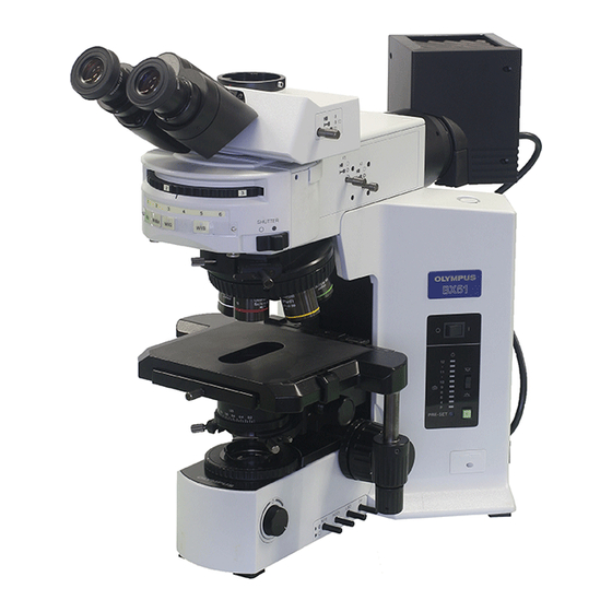
Thank you for purchasing the Olympus microscope BX2.
In order to fully utilize its performance and secure optimum condition, please read this manual before maintenance work.
Please also keep it at hand during maintenance as well as for future reference.
All rights reserved, Reproduction in whole or in part without written permission is prohibited.
Advertisement
Table of Contents

Related Manuals for Olympus BX2


Summary of Contents for Olympus BX2
- Page 1 Maintenance Manual for maintenance engineer Thank you for purchasing the Olympus microscope BX2. In order to fully utilize its performance and secure optimum condition, please read this manual before maintenance work. Please also keep it at hand during maintenance as well as for future reference.
- Page 2 Authorized Olympus dealer. Maintenance parts, grease, and other items specified in the manual can be ordered from your Authorized Olympus dealer, and subject to change without notice. The recommended maintenance schedule is shown below as reference. ( * Necessary item)
-
Page 3: Table Of Contents
2-1 Overview of maintenance....................2 2-2 Cleaning method for the optical components ..............3 3. Preparing for inspection......................6 4. BX2 inspection sheet ....................... 7 Chapter 2. INSPECTION PROCEDURE 1. Checking performance of microscope ..................8 2. Checking dirty portion ......................8 2-1 Image influence caused by dirt on each component............ -
Page 4: Chapter 1. Maintenance Procedure
BX2 MAINTENANCE MANUAL MAINTENANCE PROCEDURE Chapter 1. MAINTENANCE PROCEDURE 1. Maintenance of microscope 1) Fundamental handling a. Read the instruction manual thoroughly, handle the microscope correctly. b. Be sure to make a usual cleaning, especially after every use of microscope. -
Page 5: Guide To Maintenance
BX2 MAINTENANCE MANUAL MAINTENANCE PROCEDURE 2. Guide to maintenance 2-1 Overview of maintenance OL YMPUS BX51 OL YMPUS OL YMPUS BX51 BX51 PRE-SET PRE-SET PRE-SET Set your correct interpupillary distance. Sweep off dust on the outer surfaces Remove the revolving nosepiece, stage Note any areas suggesting a need for with the soft brush. -
Page 6: Cleaning Method For The Optical Components
BX2 MAINTENANCE MANUAL MAINTENANCE PROCEDURE 2-2 Cleaning method for the optical components Required tools: 1) Lens tissue 2) Cotton swab or tweezers etc. 3) Blower 4)Magnifier (Eyepiece is possible to be used by turning it upside down. Refer to page 10.) 5) Cleaning solution: e.g. - Page 7 BX2 MAINTENANCE MANUAL MAINTENANCE PROCEDURE HOW TO CLEAN THE FILTER Fold the lens tissue into two or three layers and moisten its shaded part with cleaning solution. Hold the filter at its edge and fold the lens paper from the lens center to outside as illustrated.
- Page 8 BX2 MAINTENANCE MANUAL MAINTENANCE PROCEDURE HOW TO CLEAN THE EYEPIECE Wrap a sheet of lens tissue Dip the wrapped lens tissue in the around a cotton swab as cleaning solution, and wipe the illustrated. If the area to be eyepiece from the center towards cleaned is large, wrap the the periphery in a circular motion.
-
Page 9: Preparing For Inspection
BX2 MAINTENANCE MANUAL MAINTENANCE PROCEDURE 3. Preparing for inspection ADJUSTMENT OF KOEHLER ILLUMINATION 1) Set the main switch “A” to “I” (ON) and adjust the brightness by turning the adjustment knob “B” . 2) Set the light path selector knob “C” to the pushed-in position. -
Page 10: Bx2 Inspection Sheet
BX2 MAINTENANCE MANUAL MAINTENANCE PROCEDURE 4. BX2 inspection sheet MODEL : CHECK DATE : S/N : CHECKING BY : CHECK CONTENTS CHECK POINT RESULT REF. PAGE 1. Electrical unit 1) When the power switch is turned on, the lamp is lit... -
Page 11: Chapter 2. Inspection Procedure
INSPECTION PROCEDURE Chapter 2. INSPECTION PROCEDURE 1. Checking performance of microscope Using the BX2 maintenance sheet (P.7), check the electrical unit, mechanical and optical performance. 2. Checking dirty portion 2-1 Image influence caused by dirt on each component The following figure shows the influence of image on each optical component if stains or dust is adhered to that portion. -
Page 12: How To Find Dirty Portion Through Observation
Please contact your Authorized Olympus dealer. Note: If dirt particles do not move by moving the above components, it is assumed that the lens and filter inside the microscope is contaminated. In this case, please contact your Authorized Olympus dealer. - 9 -... -
Page 13: How To Check Cleaning Condition
BX2 MAINTENANCE MANUAL INSPECTION PROCEDURE 2-3 How to check cleaning condition 1) When a large lens is checked, look at the lens while putting it toward bright side or breathe on the lens and observe the condition that the haze on the whole surface of the lens disappears evenly. -
Page 14: Chapter 3. Repair Procedure
BX2 MAINTENANCE MANUAL REPAIR PROCEDURE Chapter 3. REPAIR PROCEDURE 1. Optical adjustment PREPARATION Adjusting the left/right optical axis If the left/right optical axis is remarkably displaced at checking, perform the following adjustment. *Insert the cross eyepiece into the right sleeve. - Page 15 BX2 MAINTENANCE MANUAL REPAIR PROCEDURE ADJUSTMENT THE LEFT/RIGHT OPTICAL AXIS (1) Moving the cross eyepiece to the left sleeve. Work Image seen through the cross eyepiece Move the cross eyepiece to the left sleeve. If the optical axis between left and right sleeve is deviated, the center of the specimen and the cross center of eyepiece are also deviated.
- Page 16 BX2 MAINTENANCE MANUAL REPAIR PROCEDURE 3. Firmly tighten the screws which secure the Image at the end of adjustment left sleeve. - 13 -...
-
Page 17: Mechanical Adjustment
( In case where the stage movement is heavy due to hardening of grease, please contact your Authorized Olympus dealer because disassembling the stage is required for grease replacement.) Adjustment method for X/Y-wire (Refer to the figure shown below.) -
Page 18: Confirmation Of X-Wire Tesion
BX2 MAINTENANCE MANUAL REPAIR PROCEDURE 2-2 Confirmation of X-wire tension 1) Move the X-guide “A” to the center of the upper stage “B” , press”C” of the X-wire using the fan-shaped tension gauge(OT3232). If the tension does not meet the standard, adjust the tension so as to be within the standard when the X-wire comes into contact with “D”... -
Page 19: Final Adjustment
BX2 MAINTENANCE MANUAL REPAIR PROCEDURE 2-4 Final adjustment (1) Image backlash adjustment 1) Set the stage on the microscope frame. Under observation state (with 100X objective), check image backlash at the lowest knob torque. If it is over 2 microns, conduct adjustment. -
Page 20: Grease Replacement For Fine Focus Adjustment Knob Ass'y
(In case where the coarse adjustment knob ass’y is not turned evenly, please contact your Authorized Olympus dealer because it is necessary to disassemble the coarse adjustment knob ass’y and/or guide unit.) 1) Remove the screw (AB4X10SA *1) and take off the knob. -
Page 21: Electrical Adjustment
BX2 MAINTENANCE MANUAL REPAIR PROCEDURE 4. Electrical adjustment The following shows the voltage adjustment when the rheostat ass’y is replaced. (1) Replacement of rheostat ass’y 1) Remove the bottom cover “A” of microscope frame. 2) Loosen the screw of knob “B” and disassemble the parts in order of “B”... - Page 22 BX2 MAINTENANCE MANUAL REPAIR PROCEDURE (3) Adjustment procedure (BX51/52) 1) Turn on the power, and then turn the Connect it to the connector CN51 on knob “B” (P.18) to the maximum level. power board. This LED 2) In step 1), turn the trimmer VR52 (P.18) should be lit.
- Page 23 BX2 MAINTENANCE MANUAL REPAIR PROCEDURE (5) Adjustment procedure (BX41) Connect to the 1) Turn on the power, and then turn the connector CN21 on power board. knob “B” (P.18) to the maximum level. 2) While turning the trimmer (VR203”A”) on the control board, adjust the lamp output voltage to 5.9V using the digital multimeter.
-
Page 24: Connecting Diagram
BX2 MAINTENANCE MANUAL REPAIR PROCEDURE 5. Connecting diagram BX51TF/BX52TF U005 U002 U006 U001 U004 INPUT Power Board Fuse Board 100W Halogen Lamp U003 S001 CN51 X001 CN101 Displa y Board X002- X006 X007- X012 BX51TRF/BX52TRF U005 U002 100W U006 U007... - Page 25 BX2 MAINTENANCE MANUAL REPAIR PROCEDURE BX41TF/BX45TF U005 U002 U006 U001 U004 INPUT Fuse Board Power Board Halogen Lamp S001 U003 CN21 CN201 Display Board X001- X005 X006- -X011 - 22 -...
-
Page 26: Chapter 4. Troubleshooting
BX2 MAINTENANCE MANUAL TROUBLESHOOTING Chapter 4. TROUBLESHOOTING 1. Electrical problem BX51/52 Problem Cause Remedy a) Bulb intermittently lights and goes Bulb is nearly burned out. Replace bulb. out. A connector is not properly connected. Check all connectors. b) Bulb burns out almost immediately. -
Page 27: Chapter 5. Jigs And Tools / Greases And Adhesives
BX2 MAINTENANCE MANUAL JIGS AND TOOLS/GREASES AND ADHESIVES Chapter 5. JIGS AND TOOLS / GREASES AND ADHESIVES 1. List of jigs and tools Description Ref. page OT3232 Fan-shaped tension gauge (2N) OT3326 Tension gauge (1N) Cleaning tools 2, 3 3822800... -
Page 28: Chapter 6. Maintenance Parts
BX2 MAINTENANCE MANUAL MAINTENANCE PARTS Chapter 6. MAINTENANCE PARTS 1. List of maintenance parts Index No. Order No. Description Ref. page AX9870 BX41RF Instruction manual AX9853 BX41TF Instruction manual AX9857 BX45TF Instruction manual AX9869 BX51RF Instruction manual AX9855 BX51/52 Instruction manual... - Page 29 OLYMPUS OPTICAL CO., LTD 1-22-2, Nishi shinjuku shinjuku-ku, Tokyo, Japan Issued by Life Science Marketing Dept. Printed in Japan 2001 01 SK9212...
Need help?
Do you have a question about the BX2 and is the answer not in the manual?
Questions and answers