
Related Manuals for Pulsar PSBEN 5012D


Summary of Contents for Pulsar PSBEN 5012D
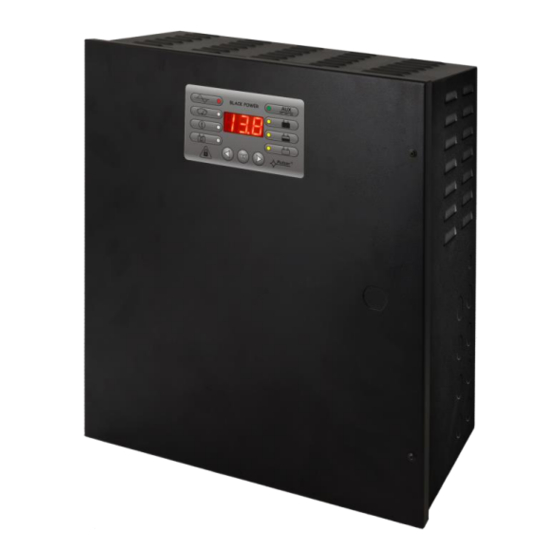
- Page 1 PSBEN 5012D v.1.0 PSBEN 13,8V/5A/40Ah/EN Buffer, switched mode power supply unit. Edition: 4 from 01.02.2013 Supersedes the: 3 from 20.11.2012edition...
-
Page 2: Table Of Contents
PSBEN5012D CONTENTS 1. FUNCTIONAL REQUIREMENTS OF THE PSU COMPLIANT WITH PN-EN 50131-6....3 2. TECHNICAL DESCRIPTION......................4 2.1. G ................................4 ENERAL DESCRIPTION 2.2. B ..................................4 LOCK DIAGRAM 2.3 D PSU’ .....................5 ESCRIPTION OF S COMPONENTS AND CONNECTORS 3. OPERATING STATUS INDICATION....................7 3.1. -
Page 3: Functional Requirements Of The Psu Compliant With Pn-En 50131-6
PSBEN5012D Features: • PN-EN50131-6 compliance, grades 1÷3 and II • jumper selectable battery charging current environmental class 0,6A/1,5A/2,2A/3A • mains supply of 230VAC • remote battery test (additional module required) • uninterrupted voltage of 13,8VDC • START button for battery activation •... -
Page 4: Technical Description
PSBEN5012D 2. Technical description. 2.1. General description. The buffer power supply has been designed in accordance with the requirements of the PN-EN 50131-6 standard, grade 1÷3 and II environmental class. It is intended for an uninterrupted supply to alarm system devices requiring stabilized voltage of 12V/DC (+/-15%). -
Page 5: Description Of Psu's Components And Connectors
PSBEN5012D 2.3 Description of PSU’s components and connectors. Table 1. Elements of the PSU pcb (see Fig. 2). Element Description PANEL – optical indication connector ; pin - adjustment of battery protection function UVP • battery protection (disconnection) off •... - Page 6 PSBEN5012D Fig. 2. The view of the PSU’s pcb. Table 2. PSU elements (see fig. 3). Element no. Description Insolation transformer PSU board (tab.1, fig.2) TAMPER; micro-switch (contacts) of tamper resistance (NC) fuse in the supply circuit (230 V AC)
-
Page 7: Operating Status Indication
PSBEN5012D 3. Operating status indication. 3.1. Control panel. The PSU is equipped with a panel with buttons and an LED display which enables reading the basic parameters of the device. The buttons are for selecting and approving a certain parameter that is to be displayed. -
Page 8: Overview Of Current Failures
PSBEN5012D Fig. 5. Menu of the display. • - PSU fault memo (30 last events) • - AUX output current measurement [A] • - AUX output voltage measurement [V] Resolution for voltage measurement amounts to 0.1V, for current measurement: 0.1A. Displayed voltage and current rates are only approximate. -
Page 9: Setting The Communication Address
PSBEN5012D 3.4.2 Setting the communication address. - press simultaneously the right and left-most buttons on the LED panel - the abbr ‘Adr’ will appear on the display - press the ‘>’ right arrow button - the abbr ‘trS’ will appear on the display - press ‘OK’... -
Page 10: Technical Outputs
PSBEN5012D 3.5 Acoustic indication. Emergency situations are acoustically indicated. The frequency and the number of signals depend on an event type (see chapter 9). The acoustic indication is off after removing an appropriate jumper (fig. 2, [5]). Table 4. Acoustic indication. -
Page 11: Input Of Collective Failure: Ext In
PSBEN5012D 3.7 Input of collective failure: EXT IN. The EXT IN (external input) technical input indicating a collective failure is intended for additional, external devices that generate the failure signal. If voltage appears at the EXT IN input, it will cause generating a PSU failure, storing the information about the event in the internal memo and sending the signal about the failure to the PSU FLT output. -
Page 12: Battery-Assisted Operation
PSBEN5012D 4. Battery-assisted operation. 4.1. Running the PSU from the battery. The PSU has been equipped with two buttons on the pcb board which enable running or disconnecting the PSU during battery-assisted operation. • Running the PSU from the battery: press the START button on the main board and hold for 1s. -
Page 13: Battery Charging Time
PSBEN5012D 4.5. Battery charging time. The PSU has a battery circuit charged with direct current. The current selection is done via I jumpers. The table below shows how long it takes to charge a (fully discharged) battery up to min. 80% of its nominal capacity. -
Page 14: Remote Monitoring (Option: Wi-Fi, Ethernet, Rs485, Usb)
PSBEN5012D 5. Remote monitoring (option: Wi-Fi, Ethernet, RS485, USB). The PSU has been adjusted to operate in a system that requires a remote control of the parameters in a monitoring centre. Transmitting data concerning PSU status is possible due to an additional, external communication module that is responsible for communication in Wi-Fi, Ethernet or RS485 standard. -
Page 15: Communication In The Ethernet Network
PSBEN5012D 5.2 Communication in the ETHERNET network. Communication in the Ethernet network is possible due to the additional interfaces: Ethernet ‘INTE’ and RS485-ETH, compliant with the IEEE802.3 standard. The Ethernet ‘INTE’ interface feature full galvanic isolation and protection against surges. It shall be mounted inside the PSU enclosure. -
Page 16: Communication In Rs485 Network
PSBEN5012D 5.3 Communication in RS485 network. Another kind of network communication is the RS485 that uses a two-wire transmission line. To implement this kind of data exchange, the PSU needs to be equipped with the additional RS485-TTL ”INTR” interface which converts data from the PSU into the RS485 standard and the USB-RS485 ”INTUR”... -
Page 17: Technical Specifications
PSBEN5012D The main panel of the program has been formulated in such a way that it is possible to divide it into smaller areas, depending on the number of power supplies. The program enables both a visualisation and an analysis of the received data. Exceeding of the acceptable parameters is indicated by highlighting in red the appropriate area or by twinkling of the indicator. -
Page 18: Psu' S Factory Settings
PSBEN5012D Voltage ’on’ – 10 ÷ 30V DC EXT IN technical input Voltage ’off’ – 0 ÷ 2V DC Level of galvanic isolation: 1500V - LEDs on the PSU’s pcb, - LED panel • output current readings Optical indication: •... -
Page 19: Installation
PSBEN5012D 7. Installation. 7.1 Requirements. The buffer PSU is to be mounted by a qualified installer, holding relevant permits and licenses (applicable and required for a given country) for 230V/AC interference and low-voltage installations. The unit should be mounted in confined spaces, in accordance with the II environmental class, with normal relative humidity (RH=90% maximum, without condensation) and temperature from -10°... -
Page 20: Operation And Use
PSBEN5012D 7. Switch on the ~230V AC supply (red AC diode and green AUX diode should be lit). 8. Check the output voltage (the PSU voltage without load and without a battery should amount to 13,7V ÷ 13,9V, with a battery or during battery charging process: 11,0V÷13,8V). If the value of the voltage requires adjustment, it should be set by the V potentiometer, monitoring the voltage at the AUX output of the PSU. -
Page 21: Psu Failure Codes
PSBEN5012D 9. PSU FAILURE CODES. Failure LED indication Technical Acoustic code outpust Fault description Causes indication actvation EPS FLT - No AC mains Battery-assisted 1 beep supply operation per 10s - Faulty main fuse MAIN PSU FLT PTC polyswitch... - Page 22 GENERAL WARRANTY CONDITIONS 1. Pulsar K. Bogusz Sp.j. (the manufacturer) grants a five-year warranty for the equipment, counted from the device’s production date. 2. The warranty includes free-of-charge repair or replacement with an appropriate equivalent (the selection is at the manufacturer’s discretion) if the malfunction is due to the manufacturer, includes manufacturing or material defects, unless such...
Need help?
Do you have a question about the PSBEN 5012D and is the answer not in the manual?
Questions and answers