
Related Manuals for Knick Unical 9000


Summary of Contents for Knick Unical 9000
- Page 1 Unical 9000/Protos II 4400 User Manual Process Analysis System Protos Service S w i t c h Unical 9000 Error Meas Service Read before installation. www.knick.de Keep for future use.
- Page 2 Unical 9000/Protos II 4400 Supplemental Directives READ AND SAVE THIS DOCUMENT FOR FUTURE REFERENCE. BEFORE ATTEMPTING TO ASSEMBLE, INSTALL, OPERATE OR MAINTAIN THE PRODUCT, PLEASE ENSURE A COMPLETE UNDERSTANDING OF THE INSTRUC- TIONS AND RISKS DESCRIBED HEREIN. ALWAYS OBSERVE ALL SAFETY INFORMATION. FAILURE TO COMPLY WITH INSTRUCTIONS IN THIS DOCUMENT COULD RESULT IN SERIOUS INJURY AND/OR PROPERTY DAMAGE.
-
Page 3: Table Of Contents
Unical 9000/Protos II 4400 Table of Contents 1 Safety............................. 1.1 Intended Use ................................. 1.2 Personnel Requirements ........................... 1.3 Safeguards................................1.4 Residual Risks ................................ 1.5 Hazardous Substances ............................1.6 Operation in Explosive Atmospheres ......................1.7 Operation and Installation..........................1.8 Maintenance and Spare Parts.......................... - Page 4 8.2.1 Corrective Maintenance on the Metering Pumps ..............81 8.2.2 Replacing the Air Pressure Switch....................83 8.2.3 Replacing the Water Pressure Switch....................84 8.2.4 Knick Repair Service ..........................84 9 Troubleshooting ........................... 85 9.1 Protos Malfunction Message ........................... 90 10 Decommissioning......................... 91 10.1 Unical: Removal ..............................
-
Page 5: Safety
This document contains important instructions for the use of the product. Always follow all instructions and operate the product with caution. If you have any questions, please contact Knick Elektronische Messgeräte GmbH & Co. KG (sometimes hereafter referred to as “Knick”) using the information provided on the back page of this document. -
Page 6: Safeguards
Drinking Water Connection If the Unical 9000 is connected to the drinking water supply, impurities caused by the rinse and process media may occur. Note the information in EN 1717. Install a suitable check valve at the water or rinse connection. -
Page 7: Hazardous Substances
• Clean non-metallic components with a damp cloth only, and allow them to dry. Certificates The current versions of the applicable certificates are available at www.knick.de. 1.7 Operation and Installation All national and local regulations relating to the installation and operation of the product in force at... -
Page 8: Maintenance And Spare Parts
Maintenance, p. 76 ➜ Spare Parts For professional corrective maintenance of the product, only use Knick genuine spare parts. Usage of any other spare parts shall constitute an unintended use of the product. Repair Service The Knick Repair Service offers professional corrective maintenance for the product to the original quality. -
Page 9: Product
• Unical 9000 in the version ordered • Service switch • 2 identical cables (to connect Unical 9000 to the service switch and Unical 9000 to the Protos in- dustrial transmitter) • Cable with plug (to connect Unical 9000 to the media adapter) •... -
Page 10: Product Code
Unical 9000/Protos II 4400 2.2.2 Product Code Unical 9000 – _ _ _ _ _ _ _ _ _ _ – _ _ _ Explosion protection For hazardous area Zone 1 – Without – Housing Steel, coated – Stainless steel, polished –... -
Page 11: Nameplates
Unical 9000/Protos II 4400 2.3 Nameplates The Unical 9000 electro-pneumatic controller is identified by a nameplate on the outside of the right wall. Unical Nameplate, Without ATEX Approval Manufacturer’s address with designation of origin IP protection Permissible ambient temperature CE mark... -
Page 12: Symbols And Markings On The Product
Unical 9000/Protos II 4400 Unical Nameplate, With ATEX Approval 1 Special conditions and danger points 8 Serial number 2 Conformity mark with identification number 9 Permissible ambient temperature 3 ATEX marking/information on explosion protection 10 Product number/Serial number/Production year and week 4 Manufacturer’s address with designation of origin... -
Page 13: Process Analysis System Design
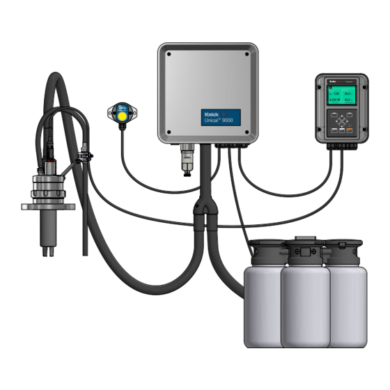
Unical 9000/Protos II 4400 2.5 Process Analysis System Design The figure shows an example installation of a Knick process analysis system. Protos Service S w i t c h Unical 9000 Error Meas Service Probe (sensor housing/immersion tube) Electro-pneumatic controller... -
Page 14: Electro-Pneumatic Controller Design And Function
Unical 9000/Protos II 4400 2.5.1 Electro-Pneumatic Controller Design and Function The electro-pneumatic controller controls the movements of the probe (sensor housing/immersion tube) into the process and service positions and the calibration and cleaning media supply lines. (4 to 7 bar) - Page 15 Unical 9000/Protos II 4400 (4 to 7 bar) Media Supply (4 to 7 bar) 1 Water pressure manometer 6 Grounding connection 2 Compressed air connection 7 Exhaust air tube (Aux 1) 3 Water connection 8 Housing with top piece equipotential bonding...
- Page 16 Unical 9000/Protos II 4400 Valve Block (4 to 7 bar) (4 to 7 bar) 1 Pressure regulator for setting the supply pressure 5 Process and service position pilot valve 2 Air pressure manometer for pressure regulator (1) 6 Water pilot valve...
-
Page 17: Media Adapter With Metering Pumps And Containers Design And Function
Unical 9000/Protos II 4400 2.5.2 Media Adapter with Metering Pumps and Containers Design and Function The media adapter with metering pumps and containers stores the calibration and cleaning media. These media are supplied to the retractable fitting via the metering pumps and the process connection. -
Page 18: Service Switch Design And Function
Unical 9000/Protos II 4400 Metering Pump with Container 1 Container (approx. capacity 3 l) 5 Check valve 2 Top piece with funnel tube 6 Float switch 3 Media adapter connection 7 Suction tube 4 Pump housing 2.5.3 Service Switch Design and Function The service switch supplies the signal to move the probe (sensor housing/immersion tube) to the service position (SERVICE limit position). -
Page 19: Process Connection Design And Function
It is recommended that changes to the Unical 9000 be carried out by the Knick Repair Service. After making the necessary changes, a functional and pressure test is carried out and, if necessary, a modi- fied nameplate is attached. -
Page 20: Installation
Unical 9000/Protos II 4400 3 Installation 3.1 General Installation Instructions • The Unical 9000 can be installed on a wall or pipe. • The mounting location must have sufficient strength and be vibration-free. • If installing outdoors, pay attention to the ambient temperature. -
Page 21: Mechanical Installation
The length of the standard process connection is measured as follows: Note: All dimensions are given in millimeters [inches]. Retractable fitting mounting Supplied Lengths Cable (to connect Unical 9000 to the industrial transmitter) Approx. 10 m Cable (to connect Unical 9000 to the service switch) Approx. 10 m 1) 2) - Page 22 Unical 9000/Protos II 4400 Service Switch Service S w i t c h Unical 9000 Error Meas Service Check the service switch (1) for damage. Prepare the holes in accordance with the Dimension Drawing. Dimension Drawings, p. 98 ➜ Fasten the service switch to the wall with screws and washers in the two holes (2).
-
Page 23: Pipe Installation
Remove the screws (4) washers (5) from the ZU0601 pipe-mount kit (3). Position the Unical 9000 on the pipe and fasten with screws and washers (5). Check for a tight fit. Refer to the User Manual for the ZU0601 accessory. - Page 24 Unical 9000/Protos II 4400 Service Switch Service S w i t c h Unical 9000 Error Meas Service Check the service switch (1) for damage. Fasten the pipe clamp (3) screws (4) to the service switch (1). Remove the nuts (5) and washers (6). Position the service switch on the pipe (2)
-
Page 25: Process Connection Installation
Unical 9000/Protos II 4400 3.2.3 Process Connection Installation (4 to 7 bar) Fasten the process connection (1) to the Unical 9000. Installing the Retractable Fitting and Media Adapter Supply, p. 26 ➜ Fasten the process connection (2) to the media adapter with metering pumps. -
Page 26: Installing The Retractable Fitting And Media Adapter Supply
Unical 9000/Protos II 4400 3.2.4 Installing the Retractable Fitting and Media Adapter Supply Overview of Supply Connections: (4 to 7 bar) (4 to 7 bar) 1 Compressed air for the process and service 4 Option Aux 1: compressed air for cleaning and... - Page 27 Unical 9000/Protos II 4400 Process Connection (4 to 7 bar) (4 to 7 bar) Remove the film (2). Unscrew the slotted nut (3) from the process connection (5). Guide the process connection tubing (5) through the opening (1). Check that the O-ring (4) is correctly seated.
- Page 28 Unical 9000/Protos II 4400 Water for Cleaning and Rinsing (Without Air Purging Aux 1 Option) (4 to 7 bar) (4 to 7 bar) (4 to 7 bar) Remove the sealing cap (3) at the control valve (2). Push the tubing DN6 (5) fully into the control valve and fasten it with a coupling nut (6).
- Page 29 Unical 9000/Protos II 4400 Aux 1 Option: Compressed Air for Cleaning and Rinsing (4 to 7 bar) (4 to 7 bar) (4 to 7 bar) Note: If the Aux 1 option (compressed air for cleaning and rinsing) is used, the water control valve remains closed.
-
Page 30: Water Supply Installation
(4 to 7 bar) Attach the connection hose with nipple G¼″ (female thread) or with nipple G¾″ (male thread) to the water supply (1). As applicable, use the ZU0656 water and air connection kit for Unical 9000. Accessories, p. 96... -
Page 31: Compressed Air Supply Installation
3.2.6 Compressed Air Supply Installation (4 to 7 bar) Attach the connection hose with nipple G ¼″ (female thread) to the compressed air supply (1). As applicable, use the ZU0656 water and air connection kit for Unical 9000. Accessories, p. 96 ➜... -
Page 32: Installing The Media Adapter With Metering Pumps And Containers
Unical 9000/Protos II 4400 3.2.7 Installing the Media Adapter with Metering Pumps and Containers Note: Port III is designed for use with aggressive media (e.g., diluted acids, diluted bases, solvents. Metering Pump: Filling the Containers, p. 66 ➜ Fit the required number of metering pumps (6) -
Page 33: Electrical Installation
NOTICE! Damage to the screw terminals due to excessive tightening torque. Tighten the screw termi- nals with a max. torque of 0.8 Nm. Connect the cable (to connect Unical 9000 to the media adapter) to terminals 45 … 51. Connect the cable (to connect Unical 9000 to the industrial transmitter) to terminals 17 … 20. - Page 34 Unical 9000/Protos II 4400 Wiring (Excerpt) Media adapter 31 32 33 34 35 36 37 38 39 40 41 42 43 44 45 46 47 48 49 50 51 Unical 9 10 11 12 13 14 15 16 17 18 19 20 21...
- Page 35 Unical 9000/Protos II 4400 Terminal Assignments Wire Color Terminal Function Manual start of program P2 (factory setting: Cal2P) via external pushbutton Do not connect Do not connect. Ground Sense B Do not connect. Ground Sense A Do not connect. Brown...
- Page 36 Unical 9000/Protos II 4400 Terminal Assignments – Under Terminal Cover These contacts are pre-wired at the factory. Wire Color Terminal Function Do not connect. Reserve Do not connect. Pilot valve Aux 2 ground Auxiliary 2 Pilot valve Aux 2 Pilot valve Aux 1 ground...
-
Page 37: Service Switch Electrical Installation
Unical 9000/Protos II 4400 3.3.1 Service Switch Electrical Installation Note: The cable is ready for connection. Do not shorten the cable, but place it rolled up with a cable tie at the installation location. Service S w i t c h... -
Page 38: Process Control System Installation
Unical 9000/Protos II 4400 3.4 Process Control System Installation Unical 9000 Inputs/Outputs Designation Input I / Level Function Output O Process / Service Normal operation Service mode active Service Mode, p. 76 ➜ Auto / Manual Automatic interval control by industrial transmitter... - Page 39 Unical 9000/Protos II 4400 Hazardous Location Connection to a Process Control System (PCS) In hazardous locations, connection to a process control system is only possible with valve control modules/switch amplifiers for communication with the Unical 9000X. The dividing line in the diagram below represents the demarcation of the hazardous location.
-
Page 40: Commissioning
Connect the compressed air supply (2). Compressed Air Supply Installation, p. 31 ➜ Note: When shutting off the compressed air upstream of the Unical 9000, the pressure may drop by a maximum of 10 % within 30 s. Check the tightness of the compressed air connection. -
Page 41: Parameter Setting
Unical 9000/Protos II 4400 5 Parameter Setting 5.1 Protos Parameter Setting See the relevant User Manuals for basic parameter setting of the Protos II 4400 industrial transmitter and the MSU4400-180 module. www.knick.de ➜ Structure of a Parameter Setting Menu pH 7.00 25.6 °C... - Page 42 Unical 9000/Protos II 4400 To control the electro-pneumatic controller Unical 9000 via Protos II 4400, the function must first be selected on the Protos: Menu Selection Parameter Setting Administrator Level MSU4400‑180 Module Channel C (Sensor/Control) Function: “Control”. Channel C (Sensor/Control) (Admin.)
-
Page 43: Calibration Timer
Installation Commissioning Program ➜ If the configuration has changed, the relevant parameters are transmitted to Unical 9000 when exiting the Unical Parameter Setting menu. 5.1.1 Calibration Timer The calibration timer starts a Unical program to calibrate the sensor after a certain calibration interval has elapsed. -
Page 44: Time Control
Unical 9000/Protos II 4400 5.1.2 Time Control Parameter Setting […C] Unical Time Control Time control is used for a time-controlled automatic start of Unical programs. • Fixed interval • Weekly program pH 7.00 25.6 °C Unical (Admin.) Control Unical 9000... - Page 45 Unical 9000/Protos II 4400 Weekly Program “Weekly Program” allows you to compile programs for individual days of the week. Description of programs Control and Service Programs, p. ➜ Up to 10 program triggers can be defined per day. Select the weekday using the arrow keys.
- Page 46 Unical 9000/Protos II 4400 Left softkey: Back: Select further program triggers accordingly. When finished, open the weekly program by pressing the left softkey: Back and configure further weekdays. When configuration is complete, press the left softkey: Back to exit the weekly program.
-
Page 47: Control And Service Programs
Unical 9000/Protos II 4400 5.1.3 Control and Service Programs Six control programs P1 … P6 and one service program P7 are available. Five program flows (P1 … P4, P7) are preset on delivery (factory setting). Two additional programs can be entered by the user (User 1, User 2). - Page 48 Unical 9000/Protos II 4400 Program Steps Program step Parameter Setting Description Program End Marks the end of the program. Probe in SERVICE Retractable fitting moves to service position (SERVICE limit position). Probe in PROCESS Retractable fitting moves to process position (PROCESS limit Follow‑up delay...
- Page 49 Unical 9000/Protos II 4400 Program step Parameter Setting Description Cal Point 1 Protos performs the first calibration step. Cal Point 2 Protos performs the second calibration step. ORP Check Protos performs the ORP check (when using ORP or pH/ORP sensors).
- Page 50 Unical 9000/Protos II 4400 Program Flow P1 “Clean” with “Continuous” Measurement Procedure Display Text Follow‑up Delay 01: Probe in SERVICE 02: Medium III 00 h 00 min 20 s 03: Water On 00 h 01 min 00 s 04: Water Off 00 h 00 min 02 s 05: Probe in PROCESS 00 h 00 min 05 s...
- Page 51 Unical 9000/Protos II 4400 Program Flow P2 “Cal 2P” (Two-point Calibration) with “Continuous” Measurement Procedure Display Text Follow‑up Delay 01: Probe in SERVICE 02: Medium III 00 h 00 min 20 s 03: Water On 00 h 01 min 00 s 04: Water Off 00 h 00 min 02 s 05: Medium I...
- Page 52 Unical 9000/Protos II 4400 Program Flow P3 “Cal 1P” (One-point Calibration) with “Continuous” Measurement Procedure Display Text Follow‑up Delay 01: Probe in SERVICE 02: Medium III 00 h 00 min 20 s 03: Water On 00 h 01 min 00 s 04: Water Off 00 h 00 min 02 s 05: Medium I 00 h 00 min 00 s...
- Page 53 Unical 9000/Protos II 4400 Program Flow P1 “Measure” with “Short-time” Measurement Procedure Display Text Follow‑up Delay 01: Water On 00 h 00 min 10 s 02: Water Off 00 h 00 min 02 s 03: Probe in PROCESS 00 h 00 min 05 s 04: Measuring Time 00 h 00 min 30 s 05: Probe in SERVICE 06: Medium III...
- Page 54 Unical 9000/Protos II 4400 Program Flow P2 “Cal 2P” (Two-point Calibration) with “Short-time” Measurement Procedure Display Text Follow‑up Delay 01: Water On 00 h 00 min 10 s 02: Water Off 00 h 00 min 02 s 03: Medium I 00 h 00 min 00 s 04: Cal Point 1 05: Water On 00 h 00 min 10 s...
- Page 55 Unical 9000/Protos II 4400 Program Flow P3 “Cal 1P” (One-point Calibration) with “Short-time” Measurement Procedure Display Text Follow‑up Delay 01: Water On 00 h 00 min 10 s 02: Water Off 00 h 00 min 02 s 03: Medium I 00 h 00 min 00 s 04: Cal Point 1 05: Water On 00 h 00 min 10 s...
- Page 56 Unical 9000/Protos II 4400 Program P4 “Parking“ Program P4 “Parking” features the program step “Wait Position”. If the program is started via the PCS inputs Bin 1 … Bin 3 (terminals 37 … 39) on the Unical 9000, it runs until the “Wait Position” is reached and remains at this point until the signal state at the PCS inputs changes: PCS inputs Bin1 ...
- Page 57 Unical 9000/Protos II 4400 Program flow: Display Text Follow‑up Delay 01: Probe in SERVICE 02: Medium III 00 h 00 min 20 s 03: Water On 00 h 01 min 00 s 04: Water Off 00 h 00 min 02 s 05: Aux 1 On 00 h 00 min 10 s 06: Aux 1 Off 00 h 00 min 02 s...
- Page 58 Unical 9000/Protos II 4400 Program P7 Service Program flow: Display Text Follow‑up Delay 01: Probe in SERVICE 02: Medium III 00 h 00 min 20 s 03: Water On 00 h 01 min 00 s 04: Water Off 00 h 00 min 02 s 05: Aux 1 On 00 h 00 min 05 s 06: Aux 1 Off...
-
Page 59: Configuring The Program Flow
Unical 9000/Protos II 4400 5.1.4 Configuring the Program Flow Parameter Setting […C] Unical Program Flow All programs P1 … P7 can be adjusted b the user. Prerequisite: All relevant settings, e.g., selection of measurement procedure, designation of media, have been specified in the submenu. -
Page 60: Calibration
Unical 9000/Protos II 4400 pH 7.00 25.6 °C Program Step (Admin.) Function Space Medium I Medium II Medium III Cal Point 1 Back Configure the program step. Description of program steps Control and Service Programs, p. 47 ➜ If monitoring has been set up for the medium in the menu , it can be switched on or off here. -
Page 61: Installation
Unical 9000/Protos II 4400 5.1.6 Installation Parameter Setting […C] Unical Installation Submenu Description, options Measurement Procedure Continuous, short-time Measurement Procedure, p. 61 ➜ Manual Control Passcode Access code for manual control (Protos Maintenance menu); Off, On (default: 2958) - Page 62 Unical 9000/Protos II 4400 • Sensocheck Glass Electrode: When using pH glass sensors, this immersion lock prevents the probe from moving into the process position with a broken sensor. For this purpose, the impedance of the glass membrane is monitored. As soon as the impedance exceeds a certain value, the message “Sad Sensoface Glass Impedance”...
- Page 63 Unical 9000/Protos II 4400 Probe Parameter Setting […C] Unical Installation Probe Submenu Description, options Probe Type Selection of retractable fitting: Ceramat, SensoGate, other Max. Travel Time Enter the maximum travel time of the probe. Input range: 0 … 9999 s If the maximum travel time is exceeded, the message “Maintenance Required”...
- Page 64 Unical 9000/Protos II 4400 Media Adapter The media adapter features three ports (Medium I … III), which can be separately configured. Parameter Setting […C] Unical Installation Media Adapter Medium … Submenu Description, options Usage Definition of equipment: Off, Metering Pump Medium Enter the medium designation, e.g., “Buffer 1”.
- Page 65 Unical 9000/Protos II 4400 Media Monitoring For complete system control, the media used (buffer solutions, cleaning solution, rinse water, ...) can be monitored in the calibration chamber for compliance with a predefined process value or tempera- ture. This ensures that the expected media also arrive in the calibration chamber of the retractable fit- ting.
-
Page 66: Operation
Unical 9000/Protos II 4400 6 Operation Unical 9000 is controlled via the Protos industrial transmitter. Control via process control system External Control via Process Control System (PCS), p. 62 ➜ The calibration and cleaning media are manually filled into the containers of the metering pumps. - Page 67 Unical 9000/Protos II 4400 Open the top piece on the metering pump (1). Fill calibration or cleaning medium into the opening (3). Containers filled. ✓ Note: The fill level can be seen through the semitransparent container.
-
Page 68: Progress Display
Unical 9000/Protos II 4400 6.2 Progress Display Each new Unical activity, e.g., a program start, is displayed on Protos. • If the measurement display or the measurement recorder is active, Protos switches to the progress display. • If one of the menus (Cal, Maint, Par, or Diag) is open, the “Unical Active” icon is shown in the status line on Protos: •... - Page 69 Unical 9000/Protos II 4400 Example of a progress display while a program is running: pH 7.00 25.6 °C Program P3: Cal 1P 1. Rinse Water On Message List Close Example of a progress display during service mode: pH 5.22 22.5 °C...
-
Page 70: Diagnostics
Unical 9000/Protos II 4400 7 Diagnostics 7.1 Protos Diagnostic Functions The Diagnostics menu shows various information on the status of the measuring system without interrupting the measurement. See the User Manual for a detailed description of the Diagnostic functions of the Protos II 4400 industrial transmitter. - Page 71 Unical 9000/Protos II 4400 Type Message text Can be signaled via PROFIBUS Contacts U200 Function Check by Unical U219 Firmware Error U220 Compressed Air Sensor U221 Immersion lock U222 Undefined Safety State U224 Leakage Sensor U225 Probe Valve Defective U226...
- Page 72 Unical 9000/Protos II 4400 Type Message text Can be signaled via PROFIBUS Contacts U242 Medium I/III/III Monitoring U243 U244 U245 Aux 1/Aux 2 Monitoring U246 U248 Water Valve Defective U249 Probe Check Counter U250 Probe Maintenance Counter U251 Calibration Error pH U252 Communication Error...
- Page 73 Unical 9000/Protos II 4400 Unical 9000 Diagnostic Functions Menu Selection Diagnostics MSU4400‑180 Module […C] Unical Diagnostics FRONT 4400-011 Module BASE 4400-021 Module MSU 4400-180 Module Memosens pH Unical Back Submenus: Unical Information Display of device type, serial no., firmware version, hardware version...
-
Page 74: Relay Contacts
Unical 9000/Protos II 4400 7.2 Relay Contacts For more detailed information and notes on wiring, see the Protos II 4400 basic unit User Manual. The Protos BASE module provides 4 relay contacts (max. AC/DC rating 30 V / 3 A each). - Page 75 Unical 9000/Protos II 4400 Settings When Using “Unical” Selection Associated message Probe Maintenance U231 Probe PROCESS Travel Time U234 Probe SERVICE Travel Time Media Adapter Maintenance U190 Container I Almost Empty U191 Container II Almost Empty U192 Container III Almost Empty...
-
Page 76: Maintenance
Activate or end service mode. Service Mode, p. 76 ➜ End Unical Service Manual Control Actuation of the Unical 9000 electro-pneumatic controller for service purposes. Manual Control, p. 77 ➜ Probe Wear Probe Wear, p. 79 Display of information on possible retractable fitting wear, resetting of check and ➜... - Page 77 • The queue is retained. Manual Control Manual control via Protos II 4400 enables actuation of the Unical 9000 electro-pneumatic control system for service purposes. Rinse water, media supply, and valve functions can be tested individually. In addition, the probe can be moved to the SERVICE and PROCESS positions.
- Page 78 Unical 9000/Protos II 4400 Behavior of the system during manual control: • Program starts are queued. • Any running program is aborted when entering manual control. • The service switch keeps its function. Pressing the service switch is signaled by the following display text: “Service Via Service Switch“.
- Page 79 Unical 9000/Protos II 4400 Probe Wear Maintenance […C] Unical Probe Wear The following is displayed: • Total probe travel = total number of travel movements performed by the retractable fitting • Check Counter • Maintenance Counter Check and maintenance counters are permanently switched on. The intervals until a message is triggered are set up in the configuration: Installation, p.
-
Page 80: Pilot Valve Functional Test
Unical 9000/Protos II 4400 8.1.2 Pilot Valve Functional Test 1 Pressure regulator 6 Process and service position pilot valve 2 Manometer: operating pressure display 7 Safety valve 3 Option: Aux 2 pilot valve 8 Manometer: pilot valve pressure display 4 Option: Aux 1 pilot valve... -
Page 81: Corrective Maintenance
Unical 9000/Protos II 4400 8.2 Corrective Maintenance 8.2.1 Corrective Maintenance on the Metering Pumps The metering pumps with containers must be cleaned; O-rings or seals must be replaced if necessary: • When changing the media • When using aggressive cleaning media •... - Page 82 Unical 9000/Protos II 4400 Replacing Seals Remove the screws from the metering pump (2). Remove the seal (3) and replace with ZU0369. Accessories, p. 96 ➜ Seal replaced. ✓ Unscrew the container (1) from the pump head (2). Push the fill level monitoring device up and replace the O‑ring (4)
-
Page 83: Replacing The Air Pressure Switch
Unical 9000/Protos II 4400 8.2.2 Replacing the Air Pressure Switch (4 to 7 bar) Shut off the compressed air supply. Turn down the pressure regulator until the manometer shows 0 bar. Unscrew the cover (3). Remove the cable from the pressure switch (6). -
Page 84: Replacing The Water Pressure Switch
✓ 8.2.4 Knick Repair Service The Knick Repair Service offers professional corrective maintenance for the product to the original quality. Upon request, a replacement unit can be obtained for the period of the repair. Further information can be found at www.knick.de. -
Page 85: Troubleshooting
Unical 9000/Protos II 4400 9 Troubleshooting Displaying Messages Go to the Diagnostics menu if the “Failure” or “Maintenance Required” icons blink on the display: Menu Selection Diagnostics Message List All active messages are displayed in the menu item with the following informa- ✓... -
Page 86: U224 Leakage Sensor
Unical 9000/Protos II 4400 Error Error Message / Possible Cause Remedy Malfunction State (Triggered By) U224 Leakage Sensor Water in Unical Check the tightness of the internal water (leakage sensor) connections. Installing the Retractable ➜ Fitting and Media Adapter Supply, p. 26 Check the leakage sensor for moisture. -
Page 87: U228 Probe Leaking
Unical 9000/Protos II 4400 Error Error Message / Possible Cause Remedy Malfunction State (Triggered By) U228 Probe Leaking Connection between process con- Check the connection between the nection and retractable fitting process connection and retractable fit- leaking. ting. Installing the Media Adapter with ➜... -
Page 88: U235 Safety Valve Defective
Unical 9000/Protos II 4400 Error Error Message / Possible Cause Remedy Malfunction State (Triggered By) Max. travel time of retractable Increase the max. probe travel time. fitting in industrial transmitter Parameter Setting […C] Unical exceeded. Preset 6 s. Installation (transmitter) Supply pressure too low. - Page 89 Unical 9000/Protos II 4400 Error Error Message / Possible Cause Remedy Malfunction State (Triggered By) U241 Rinse Medium Monitoring Incorrect medium in container. Replace the medium. Metering Pump: ➜ U242 Medium I Monitoring Filling the Containers, p. 66 U243 Medium II Monitoring Buffer medium is obsolete.
-
Page 90: Protos Malfunction Message
Unical 9000/Protos II 4400 Error Error Message / Possible Cause Remedy Malfunction State (Triggered By) U255 Calibration Error ORP Calibration temperature out of Check the calibration temperature. permissible range If necessary, adjust the limits. Sensor worn/faulty. Replace sensor. Sensor cable faulty. -
Page 91: Decommissioning
➜ 10.3 Disposal Local codes and regulations must be observed when disposing of the product. The Unical 9000 can contain various materials, depending on the version concerned. Product Code, p. 10 ➜ Customers can return their waste electrical and electronic devices. -
Page 92: Spare Parts, Accessories, And Tools
ZU0576 Media Interface The media interface converts pneumatic check-back signals into electrical signals for the electro-pneumatic controller Unical 9000 um. The use of the media inter- face is only necessary if retractable fittings from other manufacturers are used. ZU0577 Media Adapter... - Page 93 ZU0580X/1 Metering pump (PP, FKM) with container 3.0 l, Ex ZU0580X/2 Metering pump (PP, EPDM) with container 3.0 l, Ex ZU0729 Service Switch ZU0729 NC service switch for Unical 9000-NC********-*** Service S w i t c h Unical 9000 Error...
- Page 94 Unical 9000/Protos II 4400 ZU0644 Sensor Dismount Guard, Complete The sensor dismount guard measures the pressure drop or variations during operation of the retractable fitting. ZU0636 Air Purge Valve, Complete Control valve as 3/2-way valve 1 connection for air purging...
- Page 95 ZU1067/2 Multiplug service set, EPDM seal ZU1067/3 Multiplug service set, FFKM seal Conversion kit for replacing the O‑ rings and seals of the multiplug middle part ZU0933 Pump Check Valve Set, Unical 9000/Uniclean 900 ZU0933/1 Sealing ring material: FKM ZU0933/2 Sealing ring material: EPDM...
-
Page 96: Accessories
Unical 9000/Protos II 4400 11.2 Accessories ZU0601 Pipe-Mount Kit for Unical 9000 For installation of the Unical 9000 electro-pneumatic controller on a horizontal or vertical pipe ZU0606 Pipe-Mount Kit for Media Adapter For installation of the media adapter with metering pumps on a horizontal or vertical pipe. - Page 97 Unical 9000/Protos II 4400 RV01 Check Valve The RV01 check valve prevents process medium or calibration, cleaning, or rinse media from flowing back into the inlet. The check valve is selected using a product code. Check valve RV01 - _ _ _ _ Housing material, Stainless steel 1.4404...
-
Page 98: Dimension Drawings
Unical 9000/Protos II 4400 12 Dimension Drawings Note: All dimensions are given in millimeters [inches]. Unical 9000 Wall Mounting... - Page 99 Unical 9000/Protos II 4400 Unical 9000 Pipe Mounting Note: All dimensions are given in millimeters [inches].
- Page 100 Unical 9000/Protos II 4400 Media Adapter Note: All dimensions are given in millimeters [inches].
- Page 101 Unical 9000/Protos II 4400 Service Switch Wall Mounting Note: All dimensions are given in millimeters [inches]. Service Switch Pipe Mounting Note: All dimensions are given in millimeters [inches].
-
Page 102: Specifications
Unical 9000/Protos II 4400 13 Specifications Compressed Air Quality of compressed air according to ISO 8573-1:2001 Quality class 5.3.3 Solid contaminants 5 (max. 40 μm, max. 10 mg/m³) Water content for temperatures ≥ 15 °C (59 °F) Class 4 Class 3, pressure dew point -20 °C (-4 °F) or lower Water content for temperatures 5 … 15 °C (41 … 59 °F) - Page 103 Unical 9000/Protos II 4400 Media adapter with metering pumps Float Float tube PVDF Container PE-HD Degree of protection IP65 Dimensions See Dimension Drawing Dimension Drawings, p. 98 ➜ Service switch Signaling Via LEDs Service Switch Design and Function, p. 18 ➜...
- Page 104 Unical 9000/Protos II 4400 External control PCS inputs (passive) Terminals 37 … 39: Bin1 … 3 Program start P1 … P6, U = 30 V, floating, interconnected, (Ex ia IIC) galvanic isolation up to 60 V Switching voltage Active signal level < 2 V AC/DC bzw. 10 … 30 V AC/DC, configurable Connection Conductor cross-section max. 2.5 mm Enable automatic program starts, U = 30 V, floating,...
-
Page 105: Annex
Unical 9000/Protos II 4400 14 Annex Electro-pneumatic controller and media adapter pneumatic circuit diagram... - Page 106 Unical 9000/Protos II 4400 Process connection pneumatic circuit diagram...
-
Page 107: Symbols And Markings On The Display
Unical 9000/Protos II 4400 Symbols and Markings on the Display Failure in accordance with NAMUR NE 107 Blinking black cross icon in circle The NAMUR “Failure” contact is active. Error message: Diagnostics Message List Maintenance required in accordance with NAMUR NE 107 Oil can icon in square The NAMUR “Maintenance Required”... - Page 108 Unical 9000/Protos II 4400 When in measuring mode, Sensoface smileys indicate the quality of the sensor data: Happy Neutral To the left of a Diagnostics menu item set as a “Favorite”. Context menu: Open with the right softkey. Metering pump for port I, II, or III...
-
Page 109: Abbreviations
Unical 9000/Protos II 4400 Abbreviations Width across flats Auxiliary medium Brown Blue Cleaning in place Diamètre nominal (nominal size) Electromagnetic compatibility European standard EPDM Ethylene propylene diene monomer rubber Explosion protected U.S. Food and Drug Administration FFKM Perfluoro rubber Fluoro rubber... -
Page 110: Index
Unical 9000/Protos II 4400 Index Abbreviations Icons Accessories Immersion lock Additional media Initial commissioning Control valves 26 Parameter Setting 43 Parameter setting 64 Installation Electrical 33 Industrial transmitter 32 Mechanical 21 Cable lengths Parameter Setting menu 61 Calibration Pipe mounting 23... - Page 111 Unical 9000/Protos II 4400 Package contents Safeguards Personnel requirements Safety chapter Pilot valves Safety data sheets Functional test 80 Safety instructions Pipe mounting Safety valve Media adapter with metering pumps and containers Seal 24 Sensor dismount guard Service switch 24...
- Page 112 Knick Elektronische Messgeräte GmbH & Co. KG Headquarters Beuckestraße 22 • 14163 Berlin Germany Phone: +49 30 80191-0 Fax: +49 30 80191-200 info@knick.de www.knick.de Local Contacts www.knick-international.com Translation of the original instructions Copyright 2023 • Subject to change Version 1 • This document was published on February 20, 2023.
Need help?
Do you have a question about the Unical 9000 and is the answer not in the manual?
Questions and answers