Knick Protos 3400 Series User Manual
Hide thumbs
Also See for Protos 3400 Series:
- User manual (48 pages) ,
- User manual (112 pages) ,
- Short description (69 pages)
Table of Contents
Advertisement
Quick Links
Betriebsanleitung
Betriebsanleitung
User Manual
Aktuelle Produktinformation: www.knick.de
Aktuelle Produktinformation: www.knick.de
Latest Product Information: www.knick.de
Analysenmesssystem
Analysenmesssystem
Protos 3400(X)
Protos 3400(X)
Protos 3400(X)
Process Analysis System
Messmodul Protos CONDI 3400 (X)-051
Messmodul Protos CONDI 3400 (X)-051
Communication Module Protos OUT 3400(X)-071
Deutsch
Deutsch
English
zur Leitfähigkeitsmessung mit induktiven Sensoren
zur Leitfähigkeitsmessung mit induktiven Sensoren
Output Module with 2 Current Outputs and
4 Relay Outputs
The Art of Measuring.
The Art of Measuring.
Advertisement
Table of Contents

Related Manuals for Knick Protos 3400 Series


Summary of Contents for Knick Protos 3400 Series
- Page 1 User Manual Communication Module Protos OUT 3400(X)-071 Deutsch Deutsch English zur Leitfähigkeitsmessung mit induktiven Sensoren zur Leitfähigkeitsmessung mit induktiven Sensoren Output Module with 2 Current Outputs and 4 Relay Outputs Aktuelle Produktinformation: www.knick.de Aktuelle Produktinformation: www.knick.de Latest Product Information: www.knick.de...
-
Page 2: Return Of Products Under Warranty
The following trademarks are used in this manual without further marking: CalCheck®, Calimatic®, Protos®, Sensocheck®, Sensoface®, ServiceScope®, Unical®, VariPower®, Ceramat®, SensoGate® are registered trademarks of Knick Elektronische Messgeräte GmbH & Co. KG, Germany Memosens® is a registered trademark of Endress+Hauser Conducta GmbH & Co. KG, Germany Knick Elektronische Messgeräte GmbH &... -
Page 3: Table Of Contents
Table of Contents Return of Products under Warranty ..................2 Disposal ............................2 Trademarks ........................... 2 Intended Use ..........................5 Conformity with FDA 21 CFR Part 11 .................. 5 Safety Information ........................6 Application in Hazardous Locations: OUT 3400X-071 Module ......................6 Software Version ........................ - Page 4 Table of Contents ProgaLog 3000 Software (Option) for Configuration and Documentation ..26 Configuration using "ProgaLog 3000" ..............29 Configuring the Module ................30 Messages: Default settings and selection range ............33 Device limits ....................33 Current Outputs ..................... 35 Assignment of Measured Values: Start (4 mA) and End (20 mA) ......35 Configuring the current output ..................35 Current Outputs: Characteristics ..................36 Output Filter ..........................38...
-
Page 5: Intended Use
Intended Use The module is a general-purpose output module with 2 passive current outputs for transmission of any desired process variables and 4 electronic relay outputs for limit monitoring. The OUT 3400X-071 module is intended for operation in locations subject to explosion hazards which require equipment of Group II, device category 2(1), gas/dust. -
Page 6: Safety Information
• When installing the device in a hazardous location, observe the specifica- tions of the EC-Type-Examination Certificate and, if applicable, of the Control Drawing (download: www.knick.de). • Before commissioning you must prove that the device may be connected with other equipment, such as a supply unit including cables and wires. -
Page 7: Software Version
Software Version OUT 3400(X)-071 Module Device Software Protos 3400(X) The OUT 3400-071 module is supported by software version 3.0 or higher. The OUT 3400X-071 module is supported by software version 4.0 or higher. Module Software OUT 3400(X)-071 Software version 1.1 Query actual device/module software When the analyzer is in measuring mode: Press menu key, open Diagnostics menu: Device description... -
Page 9: Modular Concept
• FIU (Memosens, Unical) (software occupies 2 slots) • Unical probe controller Documentation The basic unit is accompanied by a CD-ROM containing the complete documentation. Latest product information as well as user manuals for earlier software releases are available at www.knick.de. -
Page 10: Short Description
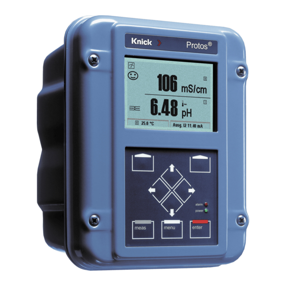
Short Description Short Description: FRONT Module 4 captive screws Transflective LC graphic display for opening the analyzer (240 x 160 pixels) (NOTICE! Make sure that the gasket between FRONT and white backlighting, high resolution and BASE is properly seated and clean!) high contrast. -
Page 11: Short Description: Menu Structure
Short Description: Menu Structure Basic functions: Calibration, Maintenance, Parameter setting, Diagnostics Menu groups Maintenance Parameter setting Diagnostics Calibration Measure Passcode: 1246 1147 2958 Operator level 1989 Administrator level Selection of BASE SYSTEM Message list Module 1 Point of meas Module 1 further FRONT Module 2... - Page 12 Short Description: FRONT Module View into the open device (FRONT module) Slot for SmartMedia card • Data recording The SmartMedia card expands the measurement recorder capacity to > 50000 records. • Exchange of parameter sets 5 parameter sets can be stored on the SmartMedia card, 2 of them can be loaded simultaneously to the analyzer and be switched by remote control.
-
Page 13: Short Description: Base Module
Short Description: BASE Module View into the open device (BASE module, 3 function modules installed) Module equipment Module identification: Plug & Play. Up to 3 modules can be combined as desired. Several input and communication modules are available. Notice Only one module can be connected in addition to a FIU 3400(X)-140/141 module. -
Page 14: Terminal Plate Out 3400-071 Module
Terminal Plate OUT 3400-071 Module Terminal Plate OUT 3400-071 Module: Attaching the Terminal Plates The terminal plates of the lower modules can be sticked to the inner side of the door. This facilitates maintenance and service. -
Page 15: Inserting The Module
Inserting the Module Thanks to the staggered arrangement of Make sure that the cable connectors and fastening screws the termi- glands are tightly closed to nal strips of all modules are easy to access. protect against humidity. Switch off power supply Open the device (loosen the 4 screws at the front) Place module in slot (D-SUB connector) Tighten fastening screws of the module... -
Page 16: Wiring Examples
Wiring Examples Current Output, Relay Contacts Wiring Example 1 Current outputs I 3, I 4 (passive, supply unit required) Output Supply unit 0(4) ... 20 mA 0(4) ... 20 mA Load Module Wiring Example 2 Electronic relay contacts Limit Max. 30 V DC contact 100 mA Module... -
Page 17: Menu Selection
Menu Selection After switching on, the analyzer performs an internal test routine and automatically detects the number and type of modules installed. Then, the analyzer goes to measuring mode. 7.00 pH 25.1 °C Menu selection Select: [enter] Return to meas Lingua 1 Pressing menu accesses menu selection. -
Page 18: Passcode Entry
Passcode Entry To enter a passcode Select the position using the left/right keys, then edit the number using the up/down keys. When all numbers have been entered, press enter to confirm. To change a passcode • Open the menu selection (menu) •... -
Page 19: Configuring The Measurement Display
Configuring the Measurement Display Select menu: Parameter setting/Module FRONT/Measurement display Pressing meas (1) returns the analyzer to the measuring mode from any function. All process variables coming from the modules can be displayed. The table on the next page describes how to configure the measurement display. - Page 20 Configuring the Menu Display measurement display Configure measurement display 7.00 pH 25.6 °C Press menu key to select menu. Menu selection Select parameter setting using arrow keys, confirm with enter. Select: “Administrator level”: Passcode 1989 Select: [enter] (default setting). Return to meas Lingua 7.00 pH Parameter setting:...
-
Page 21: Parameter Setting: Operating Levels
Parameter setting Parameter Setting: Operating Levels Viewing level, Operator level, Administrator level Note: HOLD mode (Setting: BASE module) Viewing level, Operator level, Menu Display Administrator level 11.03 pH Open parameter setting 25.6 °C From the measuring mode: Menu selection Press menu key to select menu. Select parameter setting using arrow keys, press enter to confirm. -
Page 22: Parameter Setting: Locking A Function
Parameter Setting: Locking a Function Administrator level: Enabling/locking functions for Operator level Note: HOLD mode (Setting: BASE module) Administrator level: Menu Display Enable / lock functions Example: Blocking access to the calibration adjustments from the Operator level 11.03 pH Open parameter setting 25.0°C Parameter setting (Administrator) Select Administrator level. -
Page 23: Activating Parameter Setting
Activating Parameter Setting Activating parameter setting Menu Display Parameter setting Activating parameter setting 11.03 pH 25.0°C From the measuring mode: Menu selection Press menu key to select menu. Select parameter setting using arrow keys, press enter to confirm. Select: [enter] Passcode as delivered: 1989 Return to meas Lingua... -
Page 24: Documenting Parameter Setting
Documenting Documenting Parameter Setting You must reproducibly document all parameter settings in the device to achieve a high level of system and device security according to GLP. For that purpose, an Excel file is provided (on the CD-ROM shipped with the basic device) to enter the parameter settings. - Page 25 Documenting Parameter Setting From the application window of the Excel file, select the worksheet for the module the parameter settings of which you want to document. Set the parameters of the respective module and enter the selected values in the corresponding cells of the module worksheet. NOTICE! The "HOLD"...
-
Page 26: Progalog 3000 Software (Option) For Configuration And Documentation
ProgaLog 3000 Software (Option) for Configuration and Documentation The ProgaLog 3000 software is available for convenient configuration of the Protos 3400(X) process analysis system. The user interface can be switched to the Protos display languages English, German, French, Spanish, Italian, Swedish or Portuguese. - Page 27 ProgaLog 3000 Software for Configuration and Documentation 4. Edit configuration data using ProgaLog 3000 When the configuration data have been loaded, the software lists the connected modules with all available configuration parameters: Fig.: ProgaLog 3000 configuration data The parameters are listed according to the modular device structure. All configuration parameters (except the "Sensor data details", which are deter- mined by digital sensors) can be edited at the PC.
- Page 28 ProgaLog 3000 Software for Configuration and Documentation Configuring the parameters, e.g. relay contact usage: Input errors are indicated by red highlighting: 5. Save the configuration data to SmartMedia card 6. Load the configuration data to the 7.00 pH 25.6 °C Protos 3400(X) Copy configuration (Adminstrator) Parameter setting / System control /...
-
Page 29: Configuration Using "Progalog 3000
ProgaLog 3000 Software for Configuration and Documentation Configuration using "ProgaLog 3000" In the "Configurator" menu you can preconfigure a complete Protos 3400(X) process analysis system with up to 3 modules at your PC. 1. Select your configuration from the modular system components offered in the left-hand field. -
Page 30: Configuring The Module
Configuring the Module Activating Parameter Setting Note: HOLD mode Menu Display Parameter setting Open parameter setting 7.10 pH 25.0°C From the measuring mode: Menu selection Press menu key to select menu. Select parameter setting using arrow keys, press enter to confirm. Select: [enter] Passcode 1989 (To change passcode:... - Page 31 Parameter setting Parameter Setting Default Settings and Selection Range Note: HOLD mode Parameter Default Selection / Range Output current I3 • Process variable Depending on modules installed: Off, S/cm, °C, % by wt, g/kg, Ωcm, pH, ORP, rH, etc. • Characteristic Linear Linear, trilinear, function, table •...
- Page 32 Parameter Default Selection / Range Limit contact K5 • Process variable (Module) Depending on modules installed: Off, S/cm, °C, % by wt, g/kg, Ωcm, pH, ORP, rH, etc. • Limit value (Module) Entry • Hysteresis Entry (Module) • Effective direction Min, Max •...
-
Page 33: Messages: Default Settings And Selection Range
Messages Parameter Setting Messages: Default settings and selection range Note: HOLD mode active Parameter Default Selection / Range Messages Limits max Off, device limits max., variable limits* • pH value Off, device limits max., variable limits* • ORP value Off, device limits max., variable limits* •... - Page 34 Setting the Message Parameters Messages Note: HOLD mode active Menu Display Messages Messages 7.00 pH 20.1 °C All parameters determined by the Messages (Administrator) measuring module can generate Messages pH value Messages ORP value messages. Messages rH value Messages Temperature •...
-
Page 35: Current Outputs
Current outputs Current Outputs Select menu: Parameter setting/Module OUT Note: HOLD mode active Parameter setting Menu Display BASE module Configuring the current output 7.00 pH 19.2°C • Open parameter setting Module OUT 3400-071 (Administrator) • Enter passcode Output current I3 Output current I4 •... -
Page 36: Current Outputs: Characteristics
Current Outputs: Characteristics Select menu: Parameter setting/Module BASE • Linear characteristic The process variable is represented by a linear output current curve. Output current Process variable Start • Trilinear characteristic Two additional vertices must be entered: Output current 2nd vertex Y 1st vertex Y Process variable Start... - Page 37 • Function characteristic Nonlinear output current characteristic: allows measurements over several decades, e.g. measuring very low values with a high resolution and high values with a low resolution. Required: Entering a value for 50 % output current. Output current Entry for “50 % point”: e.g.: 10 % of measured value Process variable...
-
Page 38: Output Filter
Output Filter Time interval Time averaging filter To smoothen the current output, a low-pass filter with adjustable time interval can be switched on. When there is a jump at the input (100 %), the output level is at 63 % after the time interval has been reached. The time interval can be set from 0 to 120 sec. -
Page 39: Namur Signals: Current Outputs
Current outputs: Behavior during messages NAMUR Signals: Current Outputs Behavior during messages: HOLD, 22mA signal Behavior during messages Depending on the configuration (“Messages”) 83.1 % Air 19.0°C the current outputs switch to: Behavior during messages • Currently measured value HOLD Current meas. -
Page 40: Limit Value, Hysteresis, Contact Type
Limit value Limit Value, Hysteresis, Contact Type Parameter setting/Module OUT/Relay contacts/Usage Menu Display Usage as limit value 7.00 pH Relay output: Limit 19.2°C • Open parameter setting Limit contact K5 (Administrator) • Enter passcode Variable + 04.00 pH Limit value •... -
Page 41: Maintenance, Diagnostics
Maintenance Diagnostics Module diagnostics Output status Maintenance, Diagnostics Note: During "Maintenance" the "HOLD" mode is active. Menu Display Maintenance 7.10 pH Current source (maint. menu) 22.3 °C For checking purposes, the output Current source current can be manually specified. Output current definable 0 ... 22 mA Confirm with [enter] The device is in HOLD mode. -
Page 42: Opening The Diagnostics Menu
Message list Diagnostics Functions General status information of the measuring system Select menu: Diagnostics - Message list Menu Display Diagnostics functions Opening the diagnostics menu 7.00 pH 25.6°C From the measuring mode: Menu selection Press menu key to select menu. Select diagnostics using arrow keys, confirm by pressing enter. - Page 43 Messages OUT 3400(X)-071 Module OUT messages Message type I008 Meas. processing FAIL (factory settings) I009 Module failure FAIL (Firmware Flash check sum) I070 Current I3 Span WARN I071 Current I3 <0/4 mA WARN I072 Current I3 > 20 mA WARN I073 Current I3 Load error FAIL...
-
Page 44: Specifications
Specifications Specifications Protos OUT 3400-071 Module Current output I3, passive 0/4 ... 20 mA (22 mA), floating (electrically connected with output I4) Supply voltage 3 ... 30 V, I max = 100 mA, P max = 0.8 W Load monitoring Error message if load is exceeded Overrange 22 mA in the case of a message... - Page 45 Specifications General data Explosion protection See www.knick.de (Ex module only) NAMUR NE 21 and EN 61326-1 EN 61326-2-3 Emitted interference Class B (residential area) Immunity to interference Industry Lightning protection EN 61000-4-5, Installation Class 2 Nominal operating conditions Ambient temperature: –20 ...
- Page 46 Overview of Parameter Setting Parameter setting 7.00 pH 25.6 °C Activated from measuring mode: Press menu key to select menu. Menu selection Select parameter setting using arrow keys, confirm with enter. Administrator level Access to all functions, also passcode setting. Releasing or Select: [enter] blocking functions for access from the Operator level.
- Page 47 Parameter Setting Menu Display settings: FRONT module Languages Measurement display Representation of measured values on the display: • Main display - Selecting the number of primary values displayed • Display format (one or two) • Viewing angle - Decimal places Measurement recorder Option: 2-channel, selection of process variable, start and end •...
- Page 48 Parameter Setting Menu OUT 3400(X)-071 Module Output current I3 Depending on modules installed: Off, S/cm, °C, % by wt, • Variable g/kg, Ωcm, pH, ORP, rH, etc. • Curve Linear, trilinear, function, table 0 ... 20 mA, 4 ... 20 mA •...
- Page 49 Maintenance Menu BASE Module Output current definable 0 ... 22 mA Current source OUT 3400(X)-071 Module Current source Output current definable 0 ... 22 mA Diagnostics Menu Message list List of all warning and failure messages Point of meas description Logbook Device description Hardware version, Serial no., (Module) Firmware, Options...
-
Page 50: Index
Index Administrator level 21 Application in hazardous locations 6 Attaching the Terminal Plates 14 BASE module 13 Behavior during messages 39 Cable glands 10 Change passcode 18 Configuration with ProgaLog 3000 26 Configurator menu of "ProgaLog 3000" 29 Configure measurement display 19 Configuring the current outputs 35 Configuring the module 30 Contact type 40... - Page 51 Index FDA 21 CFR Part 11 5 FRONT module 12 Graphic display 10 Hardware and software version 7 Hysteresis 40 Inserting the module 15 Installation, safety information 6 Intended use 5 LED 10 Limit value 40 Limit value, icons in the measurement display 40 Linear characteristic 36 Lock icon 22 Locking a function 22...
- Page 52 Index Modular concept 9 Module equipment 13 Modules 12 NAMUR signals, current outputs 39 Operating levels 21 Operator level 21 Output filter 38 Overview of parameter setting 46 Parameter setting 21 Parameter setting, documenting 24 Passcode entry 18 Passcode lost 18 ProgaLog 3000 software 26 Relay contacts: Wiring 16 Release (softkey function) 22...
- Page 53 Index Software version 7 Specifications 44 Start (4 mA) and end (20 mA) 35 Table of contents 3 Technical data 44 Terminal compartment 13 Terminal plate 14 Trademarks 2 Variable limits, messages 34 Viewing level 21 Wiring examples 16...
- Page 56 091968 20170630 Software version 1.x TA-201.071-KNE06...
Need help?
Do you have a question about the Protos 3400 Series and is the answer not in the manual?
Questions and answers