Table of Contents
Advertisement
Quick Links
READ AND SAVE THESE INSTRUCTIONS
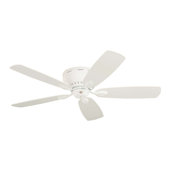
PRIMA SNUGGER
52" Ceiling Fan Owner's Manual
CF905BS01 -
CF905ORB01 -
CF905SW01 -
CF905VNB01 -
Part No. F40BP74320004
Revision: 200323
Model Numbers
Net Weight:
Questions, problems, missing parts: Before returning to the store
call Customer Service 8 a.m. - 6 p.m., Eastern, Monday-Friday
1-800-654-3545
www.emersonfans.com
Brushed Steel
Oil Rubbed Bronze
Satin White
Venetian Bronze
18.3
Lbs.
4
3
2
1
0
™
Form No. BP7432-4
U.L. Model No.: CF905-1
Advertisement
Table of Contents

Related Manuals for Emerson PRIMA SNUGGER CF905BS01


Summary of Contents for Emerson PRIMA SNUGGER CF905BS01
- Page 1 READ AND SAVE THESE INSTRUCTIONS PRIMA SNUGGER ™ 52” Ceiling Fan Owner’s Manual Model Numbers CF905BS01 - Brushed Steel CF905ORB01 - Oil Rubbed Bronze CF905SW01 - Satin White CF905VNB01 - Venetian Bronze 18.3 Net Weight: Lbs. Questions, problems, missing parts: Before returning to the store call Customer Service 8 a.m.
-
Page 2: Table Of Contents
1. To avoid possible shock, be sure electricity is turned Electric Co., Ltd. off at the fuse box before wiring, and do not operate To avoid fire, shock or injury, do not use an Emerson fan without blades. or any other brand of control not specifically approved 2. -
Page 3: Unpacking Instructions
4-Speed Slide Wall Control with Hardware Substitution of parts or accessories not designated for use with this product by Emerson could result in personal injury or property damage. Check to see that you have received the following... -
Page 4: Electrical Requirements
52” Prima Snugger Ceiling Fan. The 50-100 ft. LED Light Fixtures are recommended accessories sold separately. Your Emerson Ceiling Fan comes supplied with a Fan Remote Control which consists of a Wall Mounted Switch which allows you to regulate your Ceiling Fan Speed. -
Page 5: How To Hang Your Ceiling Fan
CAUTION CEILING To reduce the risk of injury, install the fan so that the blades are at least 7 ft. (2.1m) above the floor (Figure 1). WARNING Turning off wall switch is not sufficient. To avoid possible electrical shock, be sure electricity is turned off at the main fuse box before wiring. -
Page 6: How To Wire Your Ceiling Fan
Substitution of parts or accessories not designated possible electrical shock, be sure electricity is turned for use with this product by Emerson could result in off at the main fuse box before wiring. All wiring personal injury or property damage. - Page 7 Wire Connector (supplied) if using the supplied Wall FAN MOTOR Control (Figure 6). ASSEMBLY BLACK WIRE NOTE: If you are using an Emerson Light Fixture with your fan, see the Light Fixture Owner’s Manual for wiring. WIRE CONNECTOR FAN MOTOR ASSEMBLY...
-
Page 8: Ceiling Fan Assembly
5. Ceiling Fan Assembly Remove and retain One 10-24 x 3/8” Pan Head Screw with Lockwasher nearest the Hook on the Ceiling CEILING MOUNTING Mounting Plate (Figure 8). PLATE Loosen the remaining Two 10-24 x 3/8” Pan Head Screws several turns (Figure 8). LOOSEN TWO 10-24 x 3/8"... - Page 9 5. Ceiling Fan Assembly (Continued) CEILING Slide the Fan Housing Trim Ring over the Fan Housing TRIM RING Cover (Figure 11). Be sure to position the Flat Surface UPWARDS towards the Ceiling. FAN HOUSING COVER Figure 11 TIGHTEN TWO OPPOSING 10-24 x 3/8" PAN HEAD SCREWS Position the Fan Housing Cover over the Fan Motor Assembly.
- Page 10 5. Ceiling Fan Assembly (Continued) 10-24 x 5/16" WASHER HEAD Mount the Flange to the Blade using Three 10-24 x BLADE SCREW (3 per blade) 5/16” Washer Head Blade Screws per Blade (supplied) (Figure 14). Repeat this procedure for the other Four Blade Assemblies.
-
Page 11: Operating Your Ceiling Fan
The blue fan wire located on top of the motor assembly must be connected to a second “HOT” supply wire that is not attached to the supplied wall control. See your Emerson dealer for optional remote control options that can control the fan and SWITCH HOUSING accessory light kit using a single “HOT”... -
Page 12: Wall Control Installation
7. Wall Control Installation WARNING This control is designed to operate only one ceiling fan, Turning off wall switch is not sufficient. To avoid and not an accessory light kit. This wall control is rated possible electrical shock, be sure electricity is turned for 1.2 amps at 120 volts. - Page 13 7. Wall Control Installation (Continued) Slide the 4-Speed Slide Wall Control in the OFF position NEUTRAL TO FAN MOTOR LOAD (0). Connect One BLACK Wire from the 4-Speed Slide Wall Control to the Fan/Motor Wire with a Wire Connector (supplied) (Figure 20). Connect the Other BLACK Wire from the 4-Speed Slide Wall Control to the 120VAC Hot Wire with a Wire Connector (supplied).
-
Page 14: Energy Efficient Use Of Ceiling Fans
· Ceiling Fan/Light Controls designated specifically for use with this product. Substitution of parts or accessories not designated for use with this product by Emerson could result in WARNING personal injury or property damage. The use of any other control not specifically approved for this fan could result in fire, shock and personal injury. -
Page 15: Troubleshooting
11. Troubleshooting WARNING FOR YOUR OWN SAFETY TURN OFF POWER AT FUSE BOX OR CIRCUIT BREAKER BEFORE TROUBLESHOOTING YOUR FAN. TROUBLE PROBABLE CAUSE SUGGESTED REMEDY WARNING Make sure main power is turned OFF. WARNING Make sure main power is turned OFF. emersonfans.com Please contact 1-800-654-3545 for further assistance U.L. -
Page 16: Repair Parts
12. Repair Parts PARTS BAG U.L. Model No.: CF905-1... - Page 17 12. Repair Parts Listing Part Numbers Model Number Model Number Model Number Model Number Description CF905BS01 CF905ORB01 CF905SW01 CF905VNB01 Ceiling Mounting Plate 764136 764136-1 764136 764136-1 Fan Housing Trim Ring 764130-BS 764130-ORB 764130-SW 764130-VNB Fan Housing Cover 764131-BS 764131-ORB 764131-SW 764131-VNB Fan Blades (5 per set) 765174-DC/CH...
- Page 18 Notes U.L. Model No.: CF905-1...
-
Page 19: Ceiling Fan Limited Warranty
What We Will Do To Correct Problems: If the defect is covered by this limited warranty, Emerson will repair or replace the applicable Emerson Ceiling Fan Product at no charge to You. If repair of the Emerson Ceiling Fan Product is not practical or possible within a reasonable time and no replacement Emerson Ceiling Fan Product can be provided, Emerson will refund You the actual purchase price of Your Emerson Ceiling Fan Product. - Page 20 SERIAL NUMBER: DATE CODE: The serial number of this fan can be found on the nameplate on top of the fan housing. The date code can be found on the carton and on top of the fan housing, stamped in ink on a white label. You should record this data above and keep it in a safe place for future use.
Need help?
Do you have a question about the PRIMA SNUGGER CF905BS01 and is the answer not in the manual?
Questions and answers