Table of Contents
Advertisement
Quick Links
Advertisement
Table of Contents

Related Manuals for Digitus professional DN-65 Series


Summary of Contents for Digitus professional DN-65 Series
- Page 1 Industrial Optical Switch User Manual...
-
Page 2: Package Content
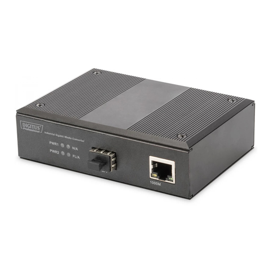
1. introduction The Industrial Switch is in an IP40 rugged strong case, Industrial Level-4 EMC design, which can work steady in harsh environments. It is an ideal solution to providing network by supporting Auto-Negotiation and LED indicators. The device supports redundant power system (12~56VDC) to guarantee the network stability. - Page 3 3. The panels and LED indicators...
-
Page 4: Dip Switch
Mark Name Function Terminal block Power supply and Grounding port PWR1 “On”: Power 1 is on and normal PWR2 “On”: Power 2 is on and normal “On”: Power over PoE port is on and normal “On”: Fiber link is in correct connection. FL/A “Blink”: Signal packet goes through Fx end 100M... - Page 5 4. Installation 4.1 DIN-rail installation Pic 1 DIN-Rail Pic 2...
-
Page 6: Wall-Mounted Installation
DIN-Rail Pic 3 The DIN installation is based on the Pic 1 and Pic 2. Unload is based on the Pic 3, then Pic2 and Pic 1. 4.2 Wall-mounted installation Pic 4 Pic 5 Pic 6 Fix hanging ears in the switch, as shown in figure 4... - Page 7 Select 4 suitable screws (diameter of screw head should be less than 6 mm, diameter of screw should be less than3.5 mm diameter, as shown in Pic 5) and fix the device on the wall as Pic 6, don’t completely tighten the screws, keep some space about 2mm.
- Page 8 4.4 Dimensions Industrial PoE Switch Industrial PoE Media Converter 4.5 Copper cable connection The standard RJ45 receptacle/connector There are 8 wires on a standard UTP/STP cable and each wire is color coded. The following shows the pin allocation and color of straight through cable and crossover cable connection:...
- Page 9 Straight Cable SIDE 1 SIDE 2 SIDE 1 1 = White/Orange 1 = White/Orange 2 = Orange 2 = Orange 3 = White/Green 3 = White/Green SIDE 2 4 = Blue 4 = Blue 5 = White/Blue 5 = White/Blue 6 = Green 6 = Green 7 = White/Brown...
-
Page 10: Technical Parameters
5. Technical parameters Power supply Input voltage: 12V~56V (redundant dual power) PSE Power: 0~30W PoE Pin: 1/2+, 3/6- Copper Port Connector: RJ-45 connector Data Rate: 10/100Mbps Auto, 10/100/1000Mbps Auto Twisted Pair cable: Cat5 UTP cable Transmission distance: 100 meter ... -
Page 11: Troubleshooting
6. Warning This product is suitable for indoor application. Place the dust cover on the fiber interface when not in use. It is dangerous to stare at the fiber transmitter with the naked eyes. Optical fiber transceivers must be used in pair. ... - Page 12 8. Responsibility Note 1. If the end user damages the product which needs to repair or maintain, he/she needs to carry the transportation fee by himself/herself and ship back to our warehouse. 2. Please contact your authorized reseller immediately, if there is any damage to the equipment during transport 3.
- Page 13 This is a Class A product. In home environment, this product may cause radio interference. In this case, the user may be required to take appropriate measures. Hereby Assmann Electronic GmbH, declares that the Declaration of Conformity is part of the shipping content. If the Declaration of Conformity is missing, you can request it by post under the below mentioned manufacturer address.
Need help?
Do you have a question about the DN-65 Series and is the answer not in the manual?
Questions and answers